
Abstract
In this paper, small scale resistance seam welding (SSRSEW) of 304 stainless steel sheet with a thickness of 0.1 mm with a capacitor discharge (CD) welding machine is investigated. The effect of the main parameters such as discharged energy, electrode force, and electrode speed on the quality of the weld seam was investigated. In order to control the speed of the electrode, the electrode wheel was mounted on a CNC machine. Mechanical tests such as tensile-shear and peel tests were used to evaluate the quality of the weld seam. Also, the failure modes were investigated in different welding conditions. The results show that the discharged energy has more effect on the weld seam strength and the maximum strength in the peel test is usually lower than the strength of the tensile-shear test. Also, discharge energy level of 14 ws and electrode force of 20 N and electrode speeds of 200 and 300 mm/min are the optimum welding condition for welding the 304 stainless steel sheets with a thickness of 0.1 mm.
Keywords
Introduction
Resistance welding processes represent a family of industrial welding processes that produce the heat required for welding through what is known as Joule (J = I2Rt) heating. In this equation, I is current, t is time, and R is resistance (p. 74). 1
Resistance welding has a lot of advantages such as inexpensive process, automated, and consume no filler material to joint steel sheets. 2 Resistance spot microwelding, sometimes called small scale resistance spot welding (SSRSW), has been increasingly employed to join thin sheet metals with a thickness less than 0.2–0.5 mm. This kind of application of resistance spot welding has many differences compared with conventional resistance spot welding (RSW), also referred to as “large-scale” resistance spot welding (LSRSW), and is mainly used for sheets larger than 0.6–0.8 mm in thickness (p. 121).3,4 Resistance microwelding is increasingly used in the fabrication of electronic components and devices such as batteries, cellular phones, interconnections in printed circuit boards, relays, sensors, air-bag diffuser screens, and medical devices.4–7
However, limited information is available for resistance microwelding of stainless steel, and mostly non-ferrous metals are welded with this welding method. Yue et al. 8 investigated the SSRSW of Ti-1Al-1Mn alloy sheets with a thickness of 0.05 mm. Welding parameters such as welding current, electrode force and welding time were studied by them. The weldability of aluminum, copper and brass sheets with a thickness of 0.2 mm was investigated by Zhou et al.9,10 Fukumoto et al. 11 welded Zr50Cu30Ni10Al10 metal glass and 304 stainless steel thin sheets with a thickness of 0.2 mm by SSRSW method and presented a method to estimate the current path area at the faying surfaces during SSRSW between bulk metallic glass and stainless steel. Ultra-thin sheets of Ti-1Al-1Mn were welded via MRSW, and diffusion of copper from the electrode tips to the welding zone was studied by Chen et al. 12 Chen 13 studied the failure mode and weld breaking force in resistance microwelding of 316L stainless steel and Pt wire. The electrode sticking mechanism and factors (welding current, weld time, tip coating, electrode force, and electrode spacing) affecting the sticking during SSRSW of very thin nickel-plated steel to nickel sheets were studied by Dong et al. 14 Mechanical properties and microstructures on dissimilar metal joints of stainless steel 301 with a thickness of 0.2 mm and aluminum alloy 1100 with a thickness of 0.4 mm by Micro-Resistance Spot Welding (μRSW) were studied by Baskoro et al. 15 Mansor et al. 16 studied the dissimilar μRSW between 0.5 mm thick austenitic stainless steel 316L and 0.5 mm thick ASTM titanium alloy grade 5 (Ti-6Al-4V). They concluded that the welding current is the most influenced/significant welding parameters for μRSW of dissimilar sheets of metal.
Resistance seam welding (RSEW) functions very similar to RSW, except that the electrodes are rotating disks (p. 83). 1 In the RSEW, several numbers of weld nuggets are overlapped along a line of the rotating electrodes to create a gas-tight seal joint. In continuous RSEW, speed is one of the main parameters in addition to parameters such as welding current, electrode force and welding time. 17
Limited research has been conducted about RSEW, especially SSRSEW, and the effect of electrode speed on the seam welding quality has been studied in a few articles. Williams and Waddell 18 determined RSEW lobe for several types of steel with different thicknesses considering the welding speed and welding current. They stated that, factors such as low electrode force, welding time and high electrical resistance of some types of steel limit the welding speed. Mira-Aguiar et al. 19 investigated the solid-state RSEW parameters to weld the galvanized steel with zinc coating. But as they pointed out, the welds were done manually, and speed and pressure were not controlled. Khosravi et al. 20 studied the effect of welding current and speed on the RSEW of galvanized and electro-galvanized steel. According to their research, welding current has a greater impact on the strength and quality of the welding than the welding speed, on the other hand, the welding speed is the most effective parameter on the weld nuggets overlap to create a continuous weld seam and as the welding speed is increased, the weld nuggets overlap will decrease. The seam welding of high-strength steel was studied by Kumar et al. 21 They stated that the weld failure occurred due to insufficient and unbalanced nugget formation, which could be rectified by modifying the welding parameters such as current, pressure and speed. Muhammad et al. 22 investigated the growth and development of the weld nugget and HAZ in RSEW of low-carbon steel with a thickness of 1 mm and presented a mathematical model to predict the development of the weld nugget.
Another effective factor in resistance welding, especially in small and micro-scale resistance welding, is welding power supply. Selection of power supply, also depends on the material and geometry of the workpiece, welding quality, control system and the cost of the welding. 23 Most large-scale resistance welding systems use the AC power supply.24,25 The disadvantages of this type of power supply are, poor control ability at short cycle times and sensitivity to the power line voltage change, therefore, this power supply is not suitable for small and micro scale resistance welding. 26 One of the suitable power supplies for small and micro-scale resistance welding is the CD power supply. A CD welding machine, allows extremely fast energy release with large peak currents. The discharge speed of a CD welder keeps the HAZ localized to a small area around the weld spot or weld seam. Fast energy discharge allows electrically and thermally conductive materials, such as copper or aluminum, to be welded. Besides, CD welding machine deliver repeatable welds even during line voltage fluctuations, because weld energy is stored before use. 27
The small-scale resistance welding with CD power supply has been studied in a limited number of articles. Mircea and Cosmin 28 welded amorphous alloy material Ni68Cr7Fe3B14Si8 with a thickness of 0.05 mm with a CD welding machine. The vitreloy 101 metallic glass ribbons with thicknesses of 0.15 mm and 0.2 mm, were welded with a CD welding machine manufactured by Miyachi company by Baca et al. 29 They developed a finite element analysis (FEA) model to explore the temperature-time relation inside the metallic glass during and following welding.
As mentioned earlier, there are not many researchers who have studied on the SSRSEW of stainless steels, and to the best of the author’s knowledge, no investigation was done on the effect of process parameters on the SSRSEW of thin stainless steel sheets with CD welding machine. Therefore, this research article specially concentrates on SSRSEW of the 304 stainless steel with a thickness of 0.1 mm with CD welding machine. The effect of main parameters such as discharged energy, electrode force and electrode speed on the quality of the weld seam was investigated by mechanical tests such as tensile-shear and peel tests and also fracture mode of the weld seam were investigated.
Experimental procedures
In this study, a 0.1 mm thick 304 stainless steel with chemical composition according to Table 1 was used.
Chemical composition of the 304 stainless steel (wt%).
Meanwhile, in order to obtain the maximum strength of the material used in this work, the tensile test was performed on the five samples with dimensions such as (100 × 10 × 0.1 mm), and therefore, the maximum tensile strength was obtained around 555 MPa.
All seam welds were performed by a CD welding machine with 1.6 F capacitor bank, maximum working voltage of 12 V, the ability to adjust the discharge time between 0.1 and 100 ms and continuous charge and discharge up to five times per second. The welding machine components are shown in Figure 1.
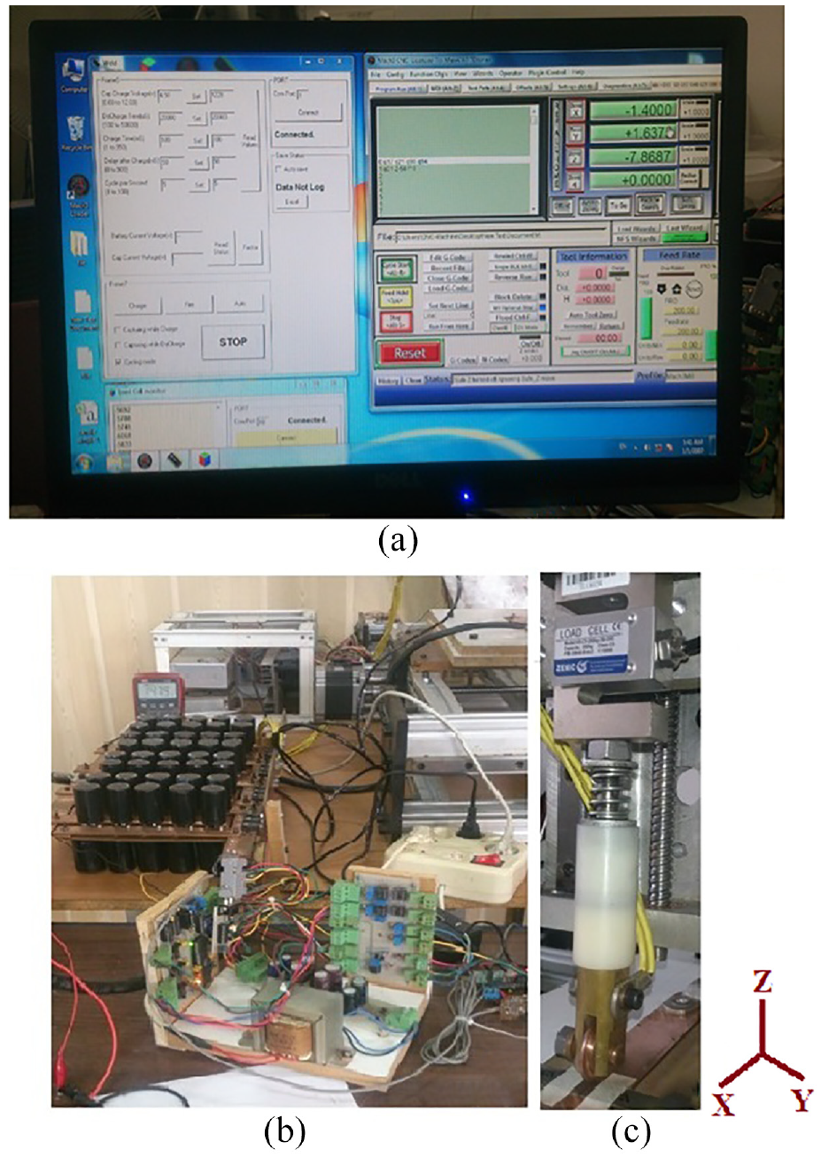
Welding machine components: (a) overview of welding control software and mach3 controller for CNC machine, (b) capacitor bank and controller hardware, and (c) electrodes and load cell for electrode force measurement.
Capacitor bank charging voltage, charging and discharging schedule and number of pulses per second, was controlled by computer and software which was developed to control the welding parameters. The electrode wheel used on the positive side of the welding machine was Cu–Cr–Zr alloy with the dimensions shown in Figure 2, and a 3 mm thick copper plate was used as the negative electrode. To control the speed of the positive electrode, the electrode wheel was connected to the z-axis of a desktop CNC device
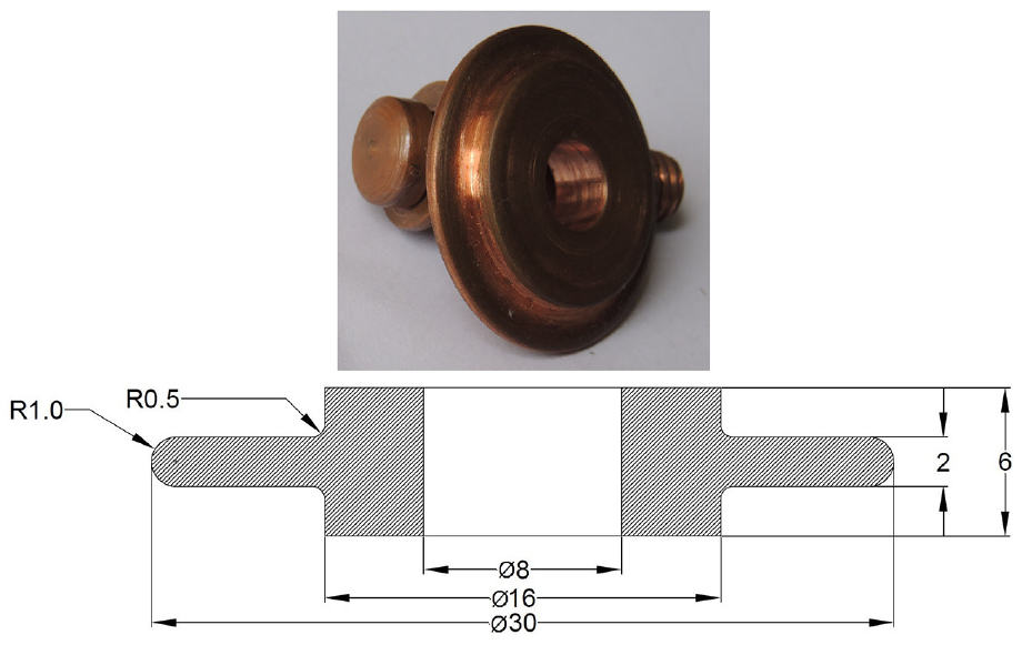
Electrode wheel dimensions (dimensions are in mm).
Also, a ZEMIC H3-C3-250 kg load cell, was attached to the z-axis of the CNC machine to measure the electrode force.
Preparation of test samples
In the RSEW, due to the high contact resistance at the edges of the two sheets at the beginning of the process, and also, passing the entire discharge current through this point, the first weld nuggets has a larger size 17 and in the most cases, expulsion is also observed at the edges of the sheets. However, by moving the electrode, due to initial bonding and the shunt effect, the next welding nuggets will have a uniform size. Also, due to the initial acceleration to reach the desired speed at the beginning of the welding and the deceleration to stop the electrode at the end of the welding, the electrode speed on the edges of the test specimens will be slightly different. Therefore, in order to eliminate the effect of the above phenomena, specimens with 15 mm width were welded initially, then to prepare final samples for mechanical tests, 2.5 mm of the edges of the welded specimens were cut. The final dimensions of the specimens are shown in Figure 3.
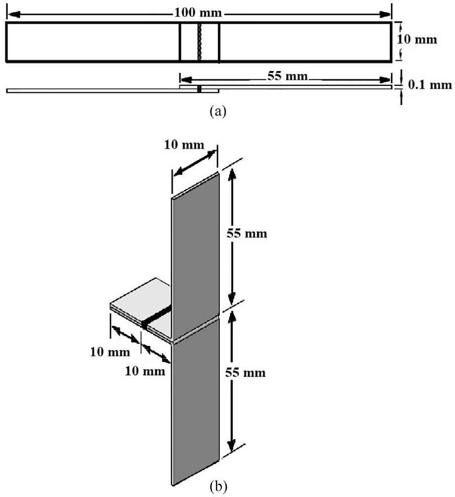
(a) Tensile-shear specimen dimensions and (b) peel test specimen dimensions.
In the resistance welding, mechanical tests such as, tensile-shear, coach peel, U-tensile and cross-tension have been used to determine the strengths and mechanical properties of spot welds under different loading conditions.30–34 In this work, the most widely used mechanical tests such as, tensile-shear and peel tests were used to investigate the maximum strength and also the failure mode of the weld seams. Mechanical tests were performed on two groups of specimens. Initially, the main specimens, including 27 specimens for the tensile-shear test and 27 specimens for the peel test were welded and tested according to the parameter levels shown in Table 2.
Levels and values of welding parameters for the main specimens.
The upper and lower values of the welding parameters shown in Table 2, were obtained by pre-experiments and by considering the very weak weld seam, observation of metal expulsion and the large distance between the weld nuggets on the weld seam. Other parameters such pulse per second, charge and discharge time were constant and all experiments were repeated three times.
Then, to draw more accurately graphs, according to the results of tests performed on the main specimens, the second group specimens consist of 47 specimens for the tensile-shear test and 47 specimens for the peel test which welded with parameter values other than the main levels given in Table 2, were tested. These values are specified in the diagrams of Figures 4, 5, 7, and 10. Mechanical tests were performed at a crosshead of 10 mm/min with an instron universal testing machine.
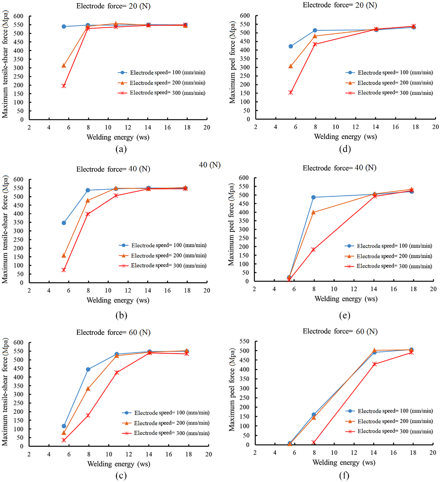
Effect of discharge energy on the tensile-shear and peel strength at different levels of electrode force and electrode speed.
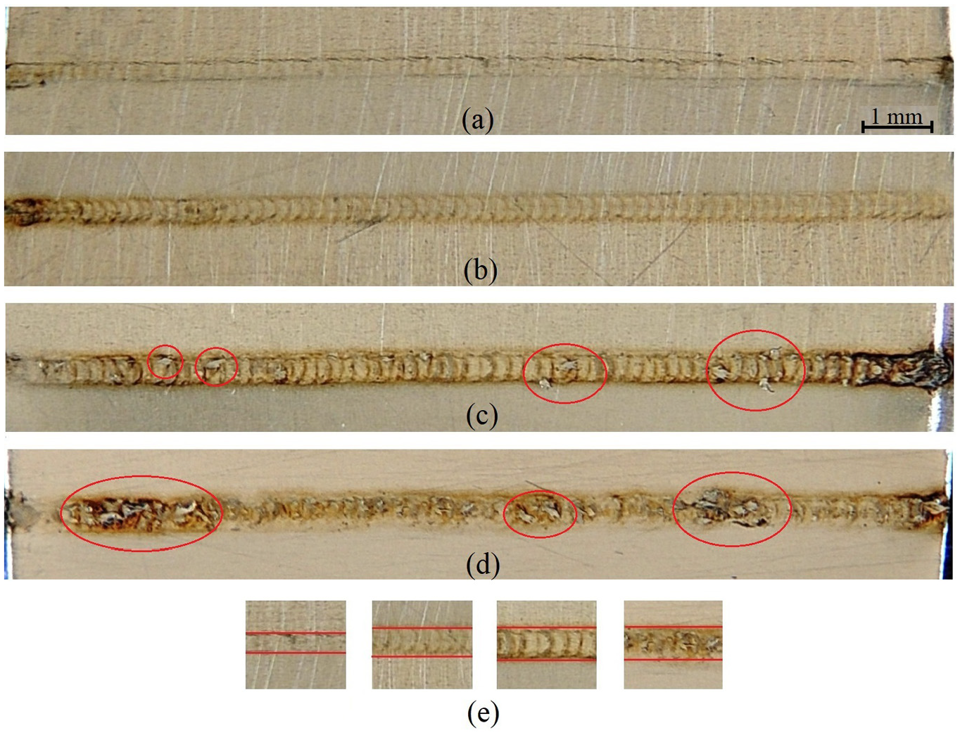
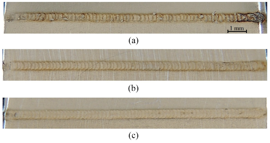
Effect of discharged energy on the size of the width of the weld seam (electrode force was 20 N and electrode speed was 100 mm/min in all cases): (a) 5.5 ws, (b) 7.92 ws, (c) 14 ws, (d) 18 ws, and (e) comparison of the weld seam width at different energy levels.
Results and discussions
In the RSW, welding current, electrode force, and welding time are the main parameters of welding. But in the RSEW, the welding time is indirectly dependent on the electrode speed, and by studying the effect of the electrode speed, the effect of welding time is also determined. The size of the weld nuggets and the weld nuggets overlap are the most important factors in increasing the strength of the weld seam. The effect of these factors is discussed in the following.
Discharged energy
As stated in all published articles on RSW, the welding current is one of the effective parameters on the size of the weld nugget and its strength.25,35,36 In the RSW with CD welding machine, the discharged energy determines the amount of welding current, and with increasing the discharged energy, the current passing through the weld zone increases, and as a result, the size of the weld nugget increases.
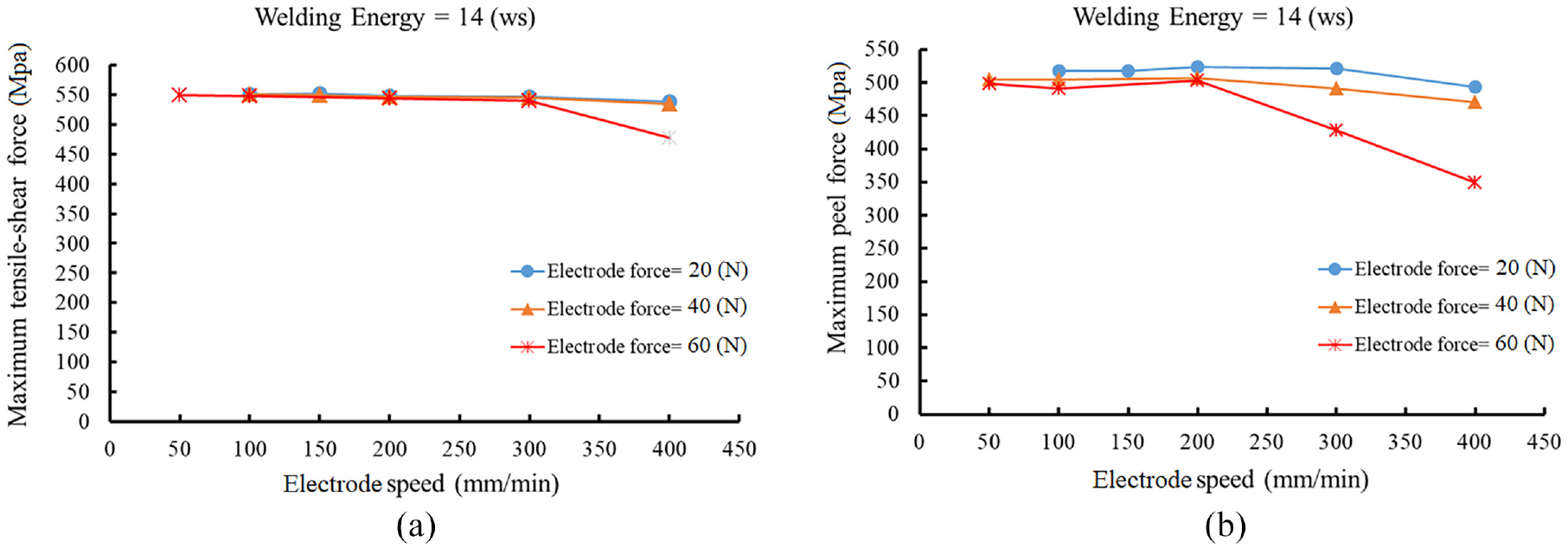
In Figure 4, the effect of discharge energy on the tensile-shear and peel strength at different levels of electrode force and electrode speed is shown. As shown in Figure 4(a) to (f), the tensile-shear strength and peel strength of weld seam increase with increasing the discharged energy. The most important reasons for increasing the mechanical strength of the weld seam with increasing the discharged energy are increases in the size of the weld nuggets and their overlap, width of the weld seam and more penetration of the melt in the direction of the sheets thickness.
In Figure 5, the effect of the discharged energy on the size of the weld nuggets and consequently on the weld seam width at discharge energy levels of 5.5, 8, and 14 ws with constant electrode force and electrode speed is shown. As shown in Figure 5, the width of the weld seam was increased by increasing the discharge energy due to the increase in the diameter of the weld nuggets. According to Figure 4(a) to (c), by increasing the discharged energy, the effect of the electrode force and electrode speed on the maximum tensile-shear strength is negligible, and in discharge energies above 14 ws, the electrode force and electrode speed do not affect the maximum tensile-shear strength of the weld seam.
But, as shown in Figure 4(d) to (f), the effect of the electrode force and electrode speed on the maximum strength of the peel test is greater respect to the tensile-shear test, so that in the electrode force of 40 N, even with the increase of discharged energy up to 18 ws, the maximum peel strength is 520 MPa, which is less than the maximum tensile-shear strength in the same welding conditions. By increasing the electrode force to 60 N according to the Figure 4(f), the peel strength decreases more and even in the discharged energy level of 18 ws, the maximum peel strength of 500 MPa at electrode speed of 100 mm/min is obtained. Boriwal et al. 37 also showed in their work (which was about RSW of galvanized steel sheets) that, the peel strength was lower than the tensile-shear strength in the equal welding conditions. The most important reason for the lower strength of the peel test compared to the tensile-shear test is the difference in the type and direction of the applied forces to the weld seam.
However, at higher discharge energies, the weld seam width is limited by the geometry of the electrode wheel edge, and further increase of discharged energy causes irregularity in the overlapping of the weld nuggets, expulsion and also larger HAZ. In Figure 5(c) and (d), the irregularity in the overlapping of the weld nuggets and expulsion at energy levels of 14 and 18 ws is shown. The approximate width of the weld seams is shown with red lines in Figure 5(e). As shown in the Figure 5(e), there is not much change in the width of the weld seams at energy levels of 14 and 18 ws.
Electrode force
Mechanical strength of the weld seam decreases with increasing the electrode force. This trend could be the result of the higher force which significantly improves the contact resistance between the interfaces, thereby decreasing electrical resistance and heat input and consequently weld nuggets diameter. 38
As shown in Figure 4(a), in the electrode force of 20 N, only at discharge energy levels below 8 ws and electrode speeds above 100 mm/min, the maximum tensile-shear strength decreases, and at discharge energy levels above 8 ws, maximum tensile-shear strength is obtained in all welding conditions. In discharge energies below 8 ws, the size of the weld nuggets is small, and by increasing the electrode speed to above 100 mm/min, the number of nuggets per unit length and the overlap between them and as a result the tensile-shear strength decreases. By increasing the electrode force to 40 N, due to the reduction of contact resistance between the two sheets and consequently reducing the generated heat in the welding area, the size of the weld nuggets become smaller, which cause the tensile-shear strength of the weld seams decrease at discharge energies less than 8 ws and all electrode speed levels. Similarly, according to Figure 4(c), when the electrode force increases to 60 N, the contact resistance between the sheets is further reduced and as a result, the size of the weld nuggets will be smaller, so that even at discharge energy level of 12 ws the tensile-shear strength is reduced. Figure 6 shows the effect of different levels of electrode force up to 80 N on the tensile-shear and peel strength of the weld seam at discharge energy level of 14 ws. As shown in Figure 4(a) to (c) and Figure 6(a), by increasing the discharge energy to levels above 14 ws, the electrode force and electrode speed do not affect the maximum tensile-shear strength of the weld seam, and only in the electrode force of 80 N and electrode speed of 300 mm/min, the tensile-shear strength decreases.
Effect of electrode force on the: (a) tensile-shear test strength and (b) peel test strength.
But as can be seen in Figure 4(d) to (f) and Figure 6(b), by increasing the electrode force, the peel strength decreases with more intensity. The main reason is the type and direction of the applied forces. This indicates that, the critical size of the weld nuggets in the tensile-shear test differs from the critical size of the weld nuggets in the peel test. For example, with respect to Figure 4(c) and (f), it can be seen that even at high energy levels of 14 and 18 ws and electrode speeds of 100 and 200 mm/min, the maximum peel strength is less than the tensile-shear strength (500 MPa vs 550 MPa). This shows that the critical size of the weld nuggets to achieve maximum strength in the peel test is greater than the critical size in the tensile-shear test.
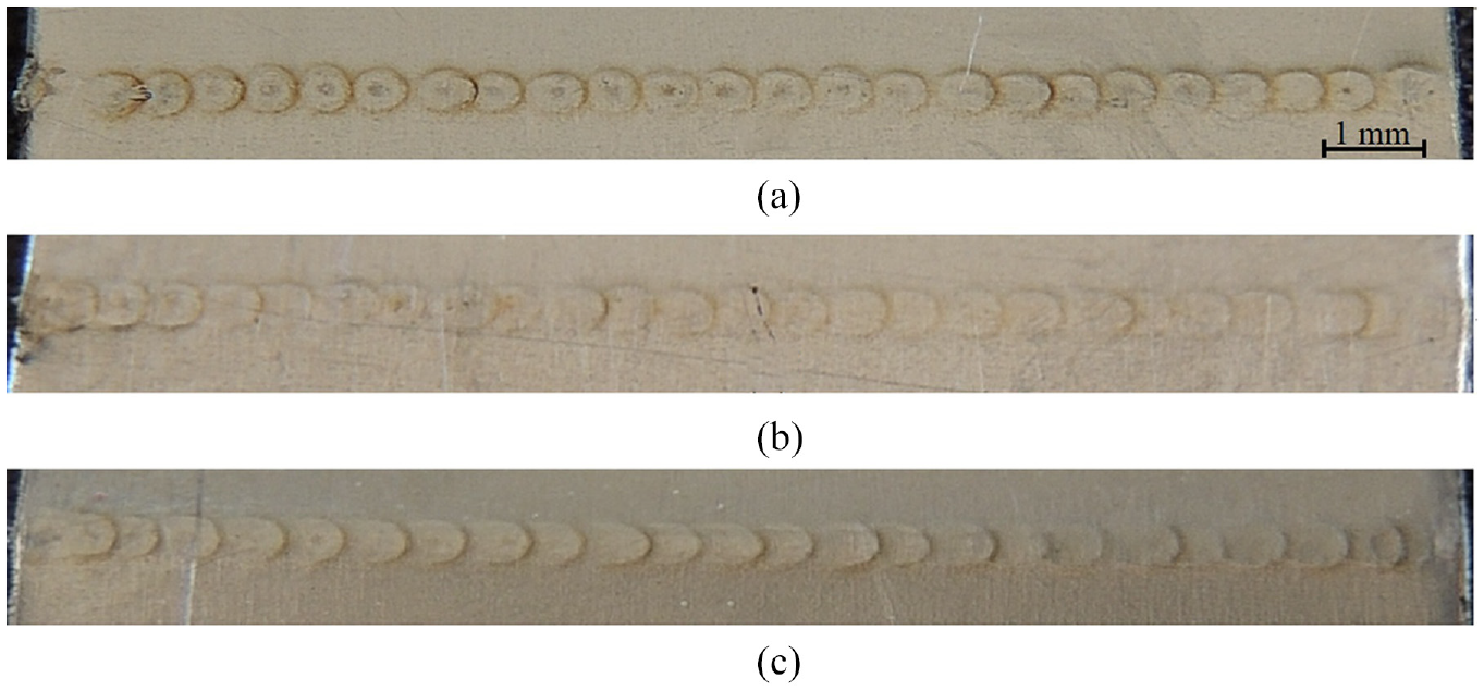
The effect of electrode force on the regularity of the weld nuggets in the weld seam is shown in Figure 7. As shown in Figure 7(a), at high energy levels, when the electrode force was low, in addition to expulsion, irregular overlap of the weld nuggets was also observed because of more melt production. By increasing the electrode force, nuggets overlap becomes more regular as shown in Figure 7(b). According to the Figure 7(c), when the electrode force increases, because of less contact resistance between the sheets and consequently less melt production, the melt penetration across the thickness of the sheets decreases.
Effect of electrode force on the regularity of the weld nuggets on the weld seam (discharge energy: 14 ws, electrode speed: 100 mm/min): (a) 20 N, (b) 40 N, and (c) 60 N.
Electrode speed
The most important effect of the electrode speed on the RSEW is regulation of the weld nuggets overlap. Welding time, which is one of the effective parameters on the size and strength of the weld nuggets, depends on the electrode speed in the RSEW. More heat input is generated with the increasing of weld time, which is favorable to reliable weld bond forming with higher mechanical strength. 38
Since in the RSEW with CD welding machine, the welding energy is discharged in pulse mode, at lower electrode speeds, one point in the weld seam is subjected to more energy pulses which the result is more heat generation and therefore more volume of melt and larger weld nugget size.
In the RSEW with CD welding machine, a weld seam consists of a number of welding nuggets that are created by moving the electrode wheel on the weld line and by increasing the electrode speed, the number of the weld nuggets per unit length and their overlap and consequently the strength of the weld seam decrease. As shown in Figure 4(a), at energy levels below 8 ws, as the electrode speed was increased, the maximum strength of tensile-shear and peel tests was reduced. At low energy levels, small weld nuggets were produced and with increasing the electrode speed, the number of weld nuggets per unit length of weld seam decreases and consequently the distance between them was increased and due to the low diameter of the nuggets, proper overlap has not occurred.
Also, according to Figure 4, when the electrode force increases, the tensile-shear strength decreases with increasing the electrode speed. The effect of electrode speed on the weld nuggets overlap and the number of weld nuggets per unit length of weld seam is shown in Figure 8. As shown in Figure 8(d), the number of weld nuggets decreases with increasing the electrode speed. The effect of the electrode speed on the maximum strength of tensile-shear and peel tests is less at the discharge energy levels higher than 14 ws, because of the increase in the diameter of the weld nuggets and consequently increase in the width of the weld seam and weld nuggets overlap.
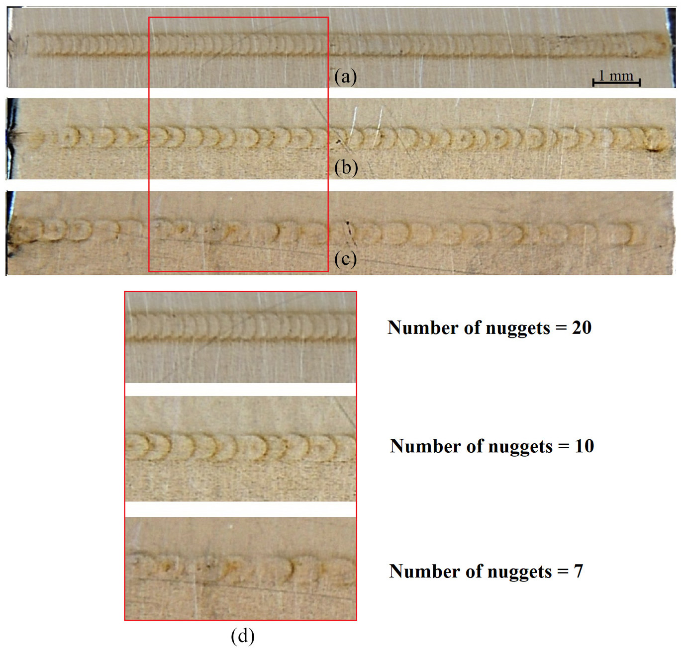
Effect of electrode speed on the weld nugget overlap in the weld seam (discharge energy: 14 ws, electrode force: 40 N): (a) 100 mm/min, (b) 200 mm/min, (c) 300 mm/min, and (d) number of nuggets at different electrode speed.
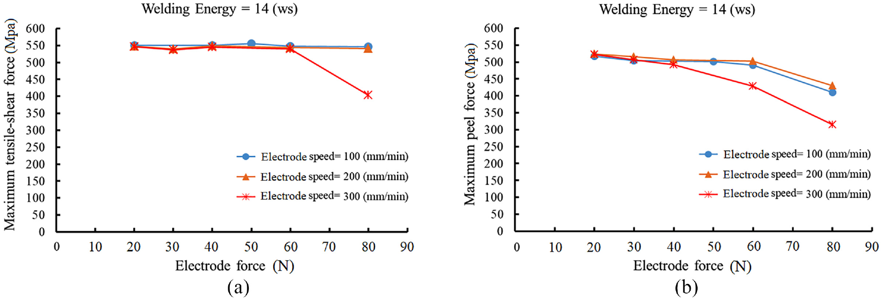
In the Figure 9(a), the effect of increasing the electrode speed on the strength of the weld seam in the discharged energy level of 14 ws is shown. As can be seen, at this level of discharge energy and electrode forces of 20 and 40 N, increasing the electrode speed does not affect the maximum strength of tensile shear test, and only in the electrode force level of 60 N, the tensile shear strength decreases by increasing the electrode speed to above 300 mm/min.
Effect of electrode speed on the: (a) tensile-shear test strength, and (b) peel test strength.
However, as shown in Figure 9(b), the maximum strength in the peel test was more sensitive to the electrode speed, and at electrode force levels of 60 N and electrode speed levels above 200 mm/min, the peel strength was decreased with more intensity. As mentioned in the previous sections, the main reasons for the decrease in the strength of the weld seam by increasing the electrode force are decrease of the weld nuggets size, the number of weld nuggets per unit length and consequently lower overlap of nuggets.
In Figure 10, the weld seams generated at constant discharge energy level of 14 ws and electrode speed of 300 mm/min at electrode force levels of 20, 40, and 60 N are shown. As shown in Figure 10(c), at higher electrode speed levels with increasing the electrode force to the 60 N, the weld nuggets were stretched along the electrode movement direction.
Influence of high electrode velocity and electrode force on stretching of weld nuggets (discharge energy: 14 ws, electrode speed: 300 mm/min): (a) 20 N, (b) 40 N, and (c) 60 N.
Failure modes
Since a weld seam in the SSRSEW consists of a number of weld nuggets with overlap along a line, its failure modes can be described by the failure mechanisms at the RSW.
Failure mode and failure mechanism, largely depend on the complex interplay between the weld geometry and the material properties of the fusion zone (FZ)/HAZ, HAZ/base metal (BM) as well as the test geometry and the stress state in each weld. 39 Figure 11 shows typical failure paths during the mechanical testing of a spot weld.
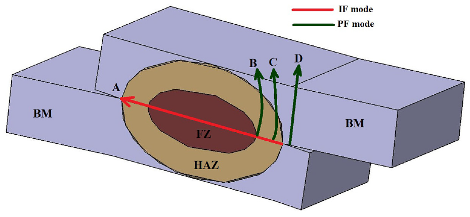
The main paths of welding nugget failure in RSW during mechanical tests.
In the mechanical tests of RSW, based on the welding condition, three failure modes occur. These failure modes are interfacial failure (IF), pullout failure (PF), and the combination of these two failure modes (IF+PF). 40
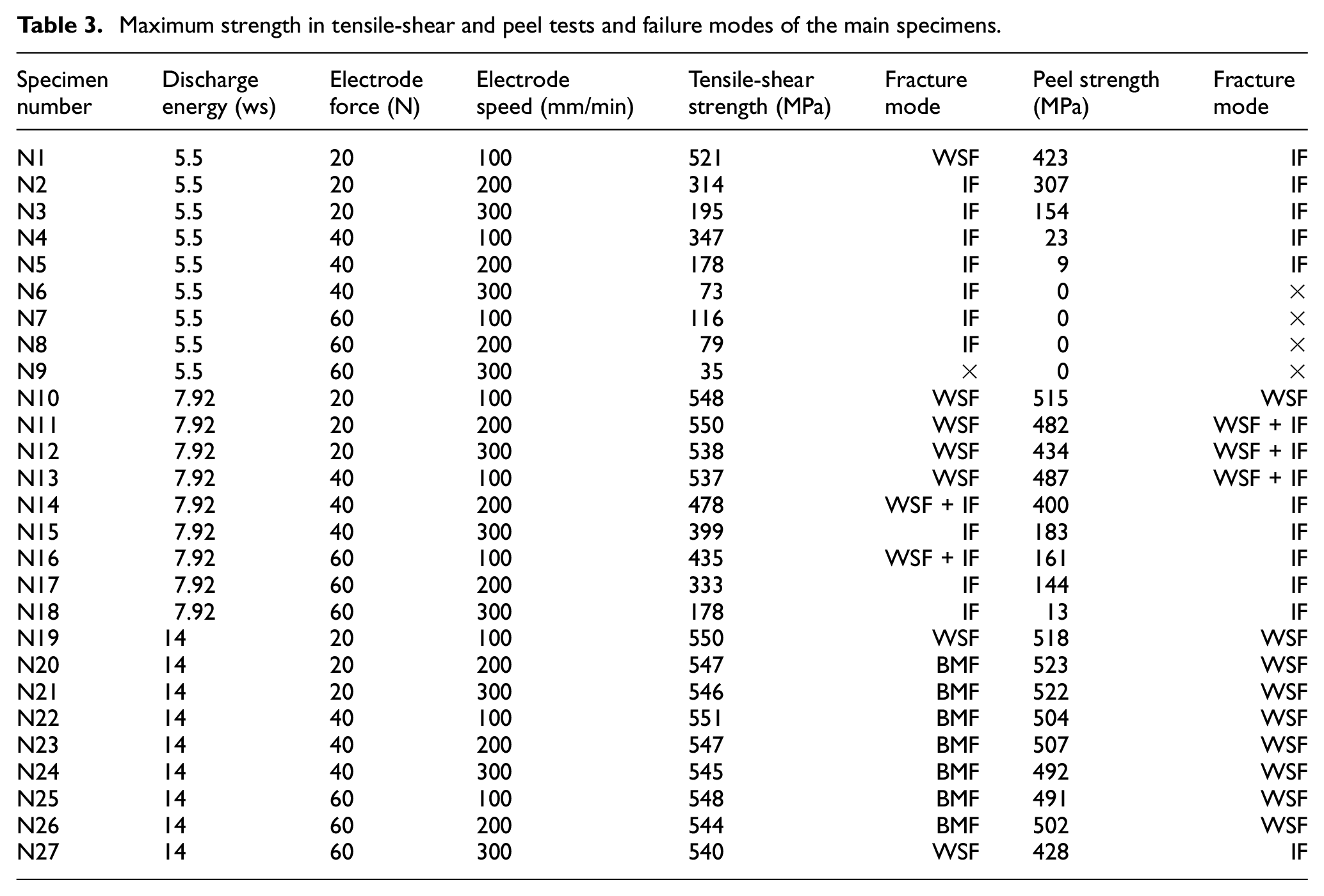
In the mechanical test of SSRSEW, four failure mode was observed, which include interfacial failure (IF), weld seam failure (WSF), combination of interfacial and weld seam failure (IF+WSF), and base metal failure (BMF). BMF mode has occurred in weld seams that consist of large weld nuggets with appropriate overlap and small HAZ. The maximum strength of tensile-shear and peel tests and failure modes in these tests are shown in Table 3.
Maximum strength in tensile-shear and peel tests and failure modes of the main specimens.
Failure mode in tensile-shear test
As shown in Figure 12(a), in RSW, the shear stress at the sheet/sheet interface is the driving force of the IF mode along the path A which shown in Figure 11, and the tensile stress at the nugget circumference is the driving force for PF mode. 39
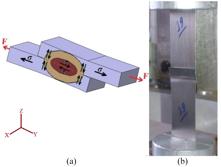
(a) Simple model describing stress distribution at interface and circumference of weld nugget during tensile-shear test, and (b) a sample of tensile-shear test.
According to the Figure 13(a) and (b), in cases that weld nuggets with small diameter was created or there was no proper overlap between the weld nuggets, the failure mode was IF mode. According to Table 3, this failure mode occurred at specimens with maximum tensile-shear strength below 450 MPa. Force-displacement graph of these specimens are shown in Figure 14. In the cases such Figure 13(c) and (d), which weld nuggets with large diameter was created and the overlap between the weld nuggets was appropriate, the failure mode was WSF or BMF.
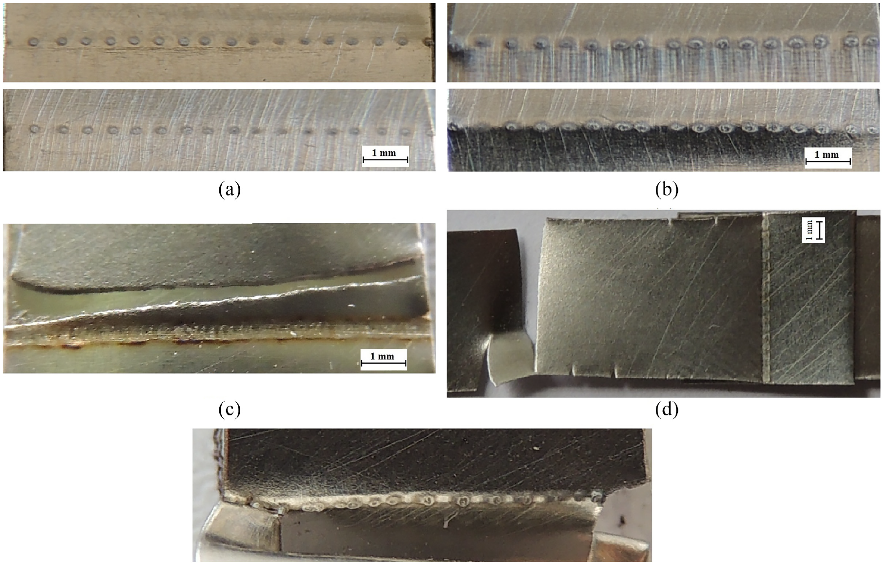
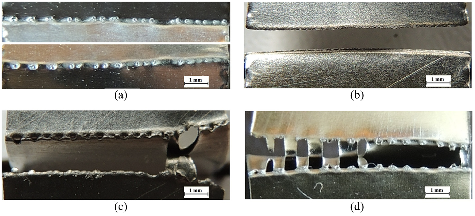
Failure modes in the tensile-shear test: (a) IF in sample No. 3 (discharge energy: 55 ws, electrode force: 20 N, electrode speed: 300 mm/min), (b) IF in sample No. 15 (discharge energy: 7.92 ws, electrode force: 60 N, electrode speed: 300 mm/min), (c) WSF in sample No. 19 (discharge energy: 14 ws, electrode force: 20 N, electrode speed: 100 mm/min), (d) BMF in sample No. 24 (discharge energy: 14 ws, electrode force: 40 N, electrode speed: 300 mm/min), and (e) combination failure mode in sample No. 14 (discharge energy: 7.92 ws, electrode force: 40 N, electrode speed: 200 mm/min).
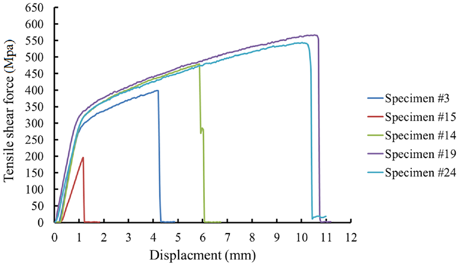
The force-displacement graph for the specimens shown in the Figure 13.
In the specimens such Figure 13(c), the failure was initiated from the nuggets at the edges of the specimens. In this failure mode, the nuggets in the edge of the weld seam were fractured in the PF mode near the HAZ, then the resulting crack was developed along the weld seam or base metal. This fracture mode has occurred in the welding condition with a high discharge energy and low electrode force and speed which larger HAZ has created. In the specimens such Figure 13(d), which the welding was done with appropriate parameters, the HAZ was small and the weld seam strength was higher than the base metal strength and fracture has occurred in the base metal. A force-displacement graph of specimens with the WSF and BMF failure mode are shown in Figure 14.
Another failure mode in the SSRSEW was a combination of IF and WSF (Figure 14(e)). According to Table 3, the maximum strength of specimens with this mode of failure was between 450 and 500 MPa. In the Figure 14, the force-displacement graph of specimen No.12 with the combination failure mode is shown.
Failure mode in peel test
In the peel test, unlike the tensile-shear test, three failure modes were observed. The maximum strength in the peel test was lower than what was obtained in the shear tensile test, because of the type of stresses and their direction.
As shown in Figure 15(a), in the peel test, the driving force of the IF mode is the tensile stress at the sheet/sheet interface. Also, due to the direction of load F, the bending moment M is also generated at the tip of the weld nugget which causes tensile stress concentration at the tip of the weld nugget. As illustrated in Figure 15(b), in the small or micro scale RSEW, due to the very low thickness of the sheets, as a result of axial force F, the specimens bend 90 degrees at the edge of the weld seam, which cause bending stress at the edge of the weld line in addition to the tensile stress caused by the axial force F, as a result, stress concentration occurs at the edge of the weld seam. Therefore, in the peel test failure occurs at the less force than the tensile-shear test. Therefore, BMF mode was not observed in the peel test.
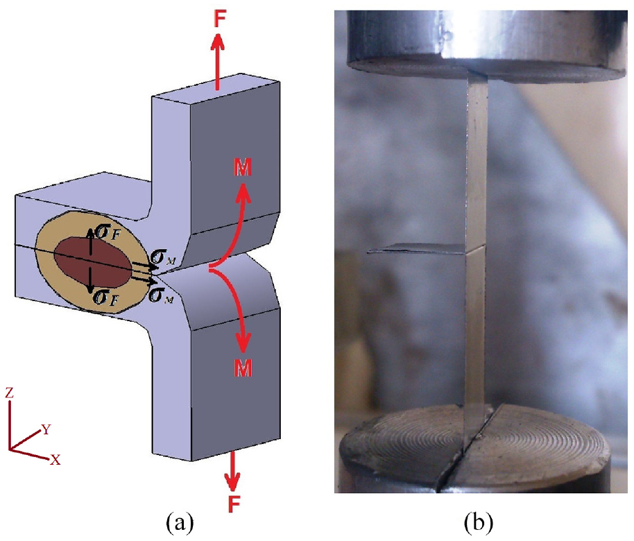
(a) Simple model describing stress distribution at interface and circumference of weld nugget during coach shear test, and (b) a sample of peel test.
During the peel test, in the specimens with small weld nugget diameter such as Figure 16(a), IF failure mode was observed. Force-displacement graph of specimens No. 3 and 12 with IF failure mode is shown in Figure 17. In the cases with peel strength above 500 MPa, the WSF failure mode was observed, and such as failure mode in the tensile-shear test, the failure was initiated from the nuggets at the edge of the weld seam and then was extended along the weld line. In Figure 16(b) and (c), specimens with WSF failure mode are shown. Force-displacement graph of these specimens are shown in Figure 17.
Failure modes in the peel test: (a) IF in sample No. 15 (discharge energy: 7.92 ws, electrode force: 40 N, electrode speed: 300 mm/min), (b) WSF in sample No. 21 (discharge energy: 14 ws, electrode force: 20 N, electrode speed: 300 mm/min), (c) WSF in sample No. 22 (discharge energy: 14 ws, electrode force: 40 N, electrode speed: 100 mm/min), and (d) combination failure mode in sample No. 12 (discharge energy: 7.92 ws, electrode force: 20 N, electrode speed: 300 mm/min).
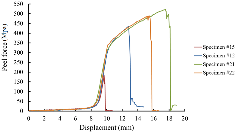
The force-displacement graph for the specimens shown in the Figure 16.
In the specimens such as specimen No. 12 with critical weld nuggets diameter and nuggets overlap, the combination failure mode has occurred as shown in Figure 16(d). According to Table 3, the maximum strength related to this failure mode was between 430 and 500 MPa depending on the welding parameters setting.
According to the maximum strength of specimens in tensile-shear and peel tests, and also the failure mode of the specimens in both tests, optimum range of welding conditions can be determined. Therefore, the welding parameters for specimen No. 10 and No. 19–26 can be considered as the optimum range of SSRSEW of 304 stainless steel with a thickness of 0.1 mm with the CD welding machine. On the other hand, if the appearance and elegance of the weld seam are also taken into account, among these specimens, the specimen No. 10 has better conditions because of its narrower and finer welding line, and sample No. 19 has the worst conditions due to irregular overlap of the weld nuggets and larger HAZ. Also, if the maximum strength in the peel test is considered as the optimum condition, specimen No. 20 and No. 21 have the best conditions compared to the other specimens, and the welding parameters for these specimens are the optimum condition.
Conclusion
In this paper, SSRSEW of 304 stainless steel sheets with a thickness of 0.1 mm with the CD welding machine was investigated. The effect of welding parameters such as discharged energy, electrode force and electrode speed on the weld seam quality was investigated. The results and conclusions could be summarized as follows.
The discharged energy has more effect on the weld seam strength than the electrode force and electrode speed, and at discharge energies above 14 ws due to the increase in the size of the weld nuggets, maximum tensile-shear strength is obtained.
Because of the type and direction of the applied stresses to the weld seam, the maximum strength in the peel test is usually lower than the strength of the tensile-shear test and only in the discharged energy level of 18 ws and the electrode force of 20 and 40 N, the maximum peel strength is equal to the tensile-shear strength.
The critical size of the weld nuggets in the tensile-shear test, differs from the critical size of the weld nuggets in the peel test and for this reason, in the same welding conditions the peel strength is less than the tensile-shear strength.
At discharge energies above 14 ws, the electrode force and electrode speed have no effect on the maximum strength of weld seam.
The most important effect of the electrode speed is to control the number of nuggets and overlap between them. Especially at energy levels below 8 ws where the small weld nuggets are formed, the distance between the weld nuggets will increase at electrode speeds above 100 mm/min and the strength of the weld seam will decrease.
In the mechanical test of RSEW four failure modes were observed, which include interfacial failure (IF), weld seam failure (WSF), combination of interfacial and weld seam failure (IF + WSF) and base metal failure (BMF).
Considering the maximum strength obtained in the tensile-shear and peel tests as well as the type of the weld seam failure mode, discharge energy level of 14 ws and electrode force of 20 N and electrode speeds of 200 and 300 mm/min are the optimum welding conditions for welding the 304 stainless steel sheets with a thickness of 0.1 mm
Further ongoing research on this regards will be on the feasibility of using this welding method to connect the fuel cells metallic bipolar plates and design of suitable electrode wheels for welding in the flow field channels and curved paths on the bipolar plates.
Footnotes
Declaration of conflicting interests
The author(s) declared no potential conflicts of interest with respect to the research, authorship, and/or publication of this article.
Funding
The author(s) disclosed receipt of the following financial support for the research, authorship, and/or publication of this article: The authors acknowledge the funding support of Babol Noshirvani University of Technology through Grant program No BNUT/370434/98.