
Abstract
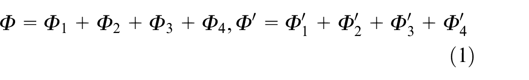
Based on the structure analysis and the working principle of cylindrical giant magnetostricve actuator (CGMA) for ball screw preload, a thermal error suppression method using oil cooling system to control the temperature is proposed. Firstly, the heat transfer model and thermal circuit model of CGMA are established; next, the steady-state temperature model and the thermal expansion displacement model of cylindrical giant magnetostrictive material (CGMM) are obtained according to the heat-transfer rules and loop analysis method in circuit analysis; finally, the design parameters of the oil-cooling temperature control system are determined by combining thermal circuit model analysis with finite element simulation analysis. Such optimization method saves a lot of computation and provides a simple way for the design of oil cooling structure. In addition, a test platform for the CGMA is established. The experimental results indicate that the measured temperatures are in good agreement with the simulation results under forced oil cooling, and the relative error is less than 5%, which proves the rationality of the temperature control system. Moreover, the output accuracy and stability of the CGMA is significantly improved with proposed oil cooling method, which further confirms the thermal error suppression method is effective. As a result, this study provides a basis for the application of CGMA in the precise adjustment of double-nut ball screw preload.
Keywords
Introduction
Giant magnetostrictive material (GMM, e.g. Terfenol-D rod) is an excellent smart material which can generate large magnetostrictive deformation under the action of external magnetic field. Giant magnetostrictive actuator (GMA) made of GMM with large elongation, large drive force, high energy density and fast response, has been widely used in heavy-load transducer, servo valve drive, active vibration control, ultra-precision machining and etc.1–5 Actually, the GMA is an electro-magneto-mechanical converter, that is, the current in the drive coil is changed into a magnetic field and the actuator outputs different displacement or outputs force under the action of the magnetic field. However, the ohmic heat generated by the drive coil can lead to the temperature rise of GMA, and the influence of temperature on which can be summarized as6,7: (1) The magnetostrictive coefficient of GMM is greatly influenced by temperature; (2) The thermal expansion and contraction effect of GMM has a great influence on the output characteristics of GMA; (3) The thermal expansion and contraction effect of other parts of GMA has a great influence on its output; (4) Excessive temperature may break through the Curie temperature of GMM and result in the disappearance of magnetostrictive properties. If the temperature rise is large, the thermal expansion displacement of GMA is equivalent to that excited by magnetic field, and its output accuracy of the displacement will be seriously affected. Therefore, it is critical to improve the output accuracy by using the cooling system to suppress the thermal deformation for the actuator with long-term work system. Many scholars have done a great deal of research work on the cooling method and obtained good cooling effects.8–10 Yamamoto et al. 11 enabled the GMA to passively compensate the thermal expansion by optimizing its structure design, but it reduced the effective drive magnetic field. Zhenyuan et al. 12 cooled the GMM rod by using forced water cooling with a spiral water tube between the GMM and coil bobbin. Lu et al. 7 adopted two water cooling cavities outside and inside the coil to suppress the heat and reduced the thermal deformation under the maximum drive current to 0.02 μm. Wu and Xu 13 proposed a phase changing water cooling combination temperature control system and obtained satisfactory results, which made the output accuracy of the actuator be up to 0.1 μm. Zhu and Ji 14 combined passive compensation with active water cooling to achieve high control accuracy of the thermal displacement. The hollow copper tube with recirculated cooling water is used to make the GMA keep constant temperature, but the structure is complex. 15 The finite element analysis method was adopted to optimize the cooling water system of the magnetostrictive jet dispenser and the thermal characteristics was improved significantly, which lower the temperature increasement by 13.6°C and the thermal expansion displacement by 8.1 μm. Such forced water cooling method has obvious heat dissipation effect, however, the mechanical structure and thermal model are complex, and the electrical insulation is poor. 16 Kwak et al. 17 improved the positioning accuracy of GMA with a built-in air cooling method and concluded the optimal cooling condition with a cooling air temperature of 18°C and a velocity of 2.8 m/s by thermal analysis. Semiconductor refrigeration is introduced into the cooling system of GMA with several semiconductor thermopiles installed on both ends of the cool bobbin. At the same time, the cooling water is forced to flow past the hot end of thermopile, which can accelerate the heat dissipation and improve the cooling efficiency. 18 In addition, the temperature rise suppression method using phase change material, the passive thermal deformation compensation method, the software programming temperature control method have been applied to the cooling system of GMA, but these methods are suitable for the application with short-time control, low power, and low control precision.11,19,20
Compare with the traditional ball screw preload system, the magnetostrictive ball screw preload system has advantages of automatic preload adjustment, fast response, and high precision. However, the cylindrical giant magnetostricve actuator (CGMA), which is a core element for preload adjustment, is driven by the coil current, and the heat generated from the drive coil will affect its adjustment accuracy and introduce thermal deformation error to the nut. Therefore, to improve the precision of the adjustment for ball screw preload, a novel forced oil cooling method, which can directly cool the heat source of the CGMA, is proposed on the basis of the above temperature control methods in this paper. Firstly, the steady-state heat transfer model is established based on Fourier’s law, Newton’s law of cooling and equivalent thermal resistance theory, and the thermal error is analyzed theoretically. Next, the simulation results of steady-state thermal field with natural cooling and forced oil cooling are discussed and the parameters of the cooling system are determined. Finally, the heat transfer test platform of the CGMA for ball screw preload is established and the test results are in good agreement with the simulation results, which provides a great contribution to the design and application of the CGMA for ball screw preload.
CGMA structure and working principle
As shown in Figure 1, the magnetostrictive preload system mainly consists of nut A, nut B, screw, and CGMA. The screw shaft passing through the CGMA which is connected with the nut on both sides, and the preload is controlled by the output force of the CGMA. On the basis of spacer preload principle, initial preload force is determined according to the dynamic load rating. Real-time preload adjustment is done by changing current of the drive coil, which drives the CGMA to output different displacement or preload force to reduce the axial clearance caused by fatigue wear or varying axial load. Moreover, the preload can be monitored in real time through the force sensor. As a result, a close-loop control system is formed and the double-nut ball screw can be in an optimal preload state by controlling the current.
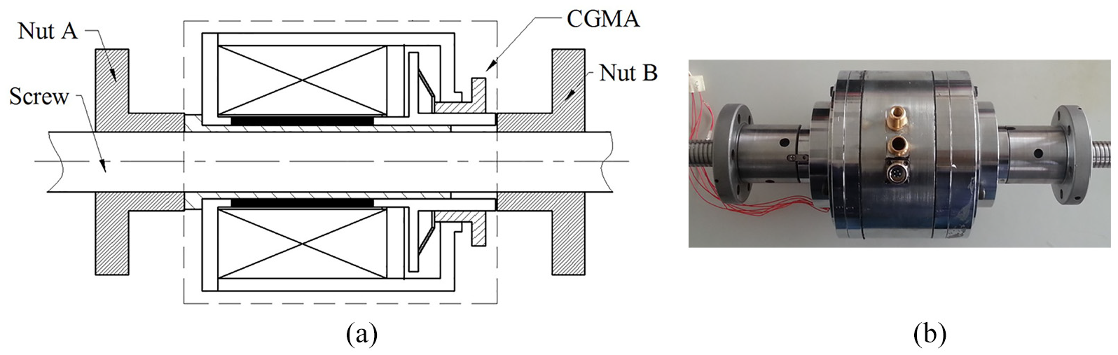
Schematic diagram of the magnetostrictive preload system: (a) two-dimensional design diagram and (b) physical map.
To make the screw shaft pass through and be easy to install for ball screw preload, the CGMA is designed to be hollow by using cylindrical giant magnetostrictive material (CGMM) as shown in Figure 2(a). When the CGMA works for preload adjustment, the Joule heat generated by the drive coil will cause thermal deformation error, so the cooling measures should be taken to compensate the error and the forced oil cooling method is adopted in this paper. As shown in Figure 2(b), a tube rubber, an oil inlet, an oil outlet, and a cooling cavity forms the temperature control structure. For easy installation, the cooling oil inlet and outlet are designed on the same side, however, such structure can cause the cooling oil fail to circulating. To prevent cooling oil coming out directly from inlet to the outlet without circulating, a rubber tube is connected with the oil inlet to the bottom of the cooling cavity, which can ensure the circulation of the cooling oil. This cooling method has the following advantages: (1) No additional structure is developed, so the CGMA structure is simple and compact. (2) The heating source is immersed directly in the cooling oil so that the cooling efficiency is high. (3) The good insulation of the cooling oil keeps the actuator away from the danger of short circuit and being rusted.
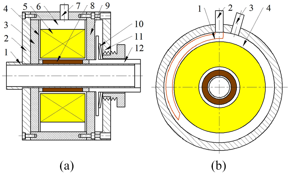
Temperature control system of the CGMA: (a) axial section of the CGMA (1 sleeve, 2 base, 3 magnetic yoke 1, 4 coil bobbin, 5 drive coil, 6 cooling cavity, 7 cooling tube, 8 CGMM, 9 magnetic yoke 2, 10 disc spring, 11 head cover, 12 output shaft) and (b) radial section of the CGMA (1 rubber tube, 2 oil inlet, 3 oil outlet, 4 cooling cavity).
Heat transfer and thermal deformation analysis of CGMA
Heat transfer model of CGMA
Since the CGMA for ball screw preload is excited by the DC or low frequency current, the main heat source is the Ohmic heat from the drive coil without considering the eddy current loss and the hysteresis losses of the CGMM. The CGMA is an axisymmetric structure and its simplified heat transfer model is shown in Figure 3, in which the effects of disc spring, output rod, bolts, and other small structures are neglected. Most of the heat generated by the drive coil is taken away by the circulating oil in the cooling cavity, and the other dissipates into the air through the conduction. Accordingly, there are two basic heat transfer modes in the CGMA under forced oil cooling, which are heat conduction and heat convection. In Figure 3, the drive coil is the heat source, and it has four heat transfer pathways: first, the heat is conducted to the peripheral air through the coil bobbin, the magnetic yoke 1 and the base; second, the heat is conducted to the peripheral air through the coil bobbin and the magnetic yoke 2; third, the heat is conducted to the air inside the center hole of the CGMA through the coil bobbin, the CGMM and the sleeve; fourth, the heat is conducted to the peripheral air through the cooling cavity and the housing. Based on Fourier’s law, Newton’s law of cooling and equivalent thermal resistance theory in literatures,14,21–23 the equivalent thermal circuit model is shown in Figure 4. As shown in Figure 4(a), the steady-state equivalent thermal circuit model of the CGMA is under the natural cooling, namely, the cooling cavity is filled with air. As shown in Figure 4(b), the steady-state equivalent thermal circuit model is under the forced convection, namely, the oil in the cooling cavity is forced to flow by the action of the oil pump. In steady state, the peripheral air is connected to the internal air and both have the same temperature, so the relationship between the four thermal circuits is parallel, in which T represents the temperature,
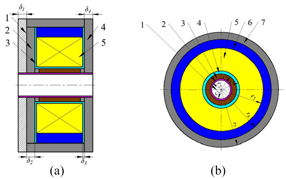
Schematic diagram of the heat transfer model: (a) axial direction (1 base, 2 magnetic yoke 1, 3 coil bobbin, 4 magnetic yoke 2, 5 drive coil) and (b) radial direction (1 air, 2 sleeve, 3 CGMM, 4 coil bobbin, 5 drive coil, 6 cooling cavity, 7 housing).
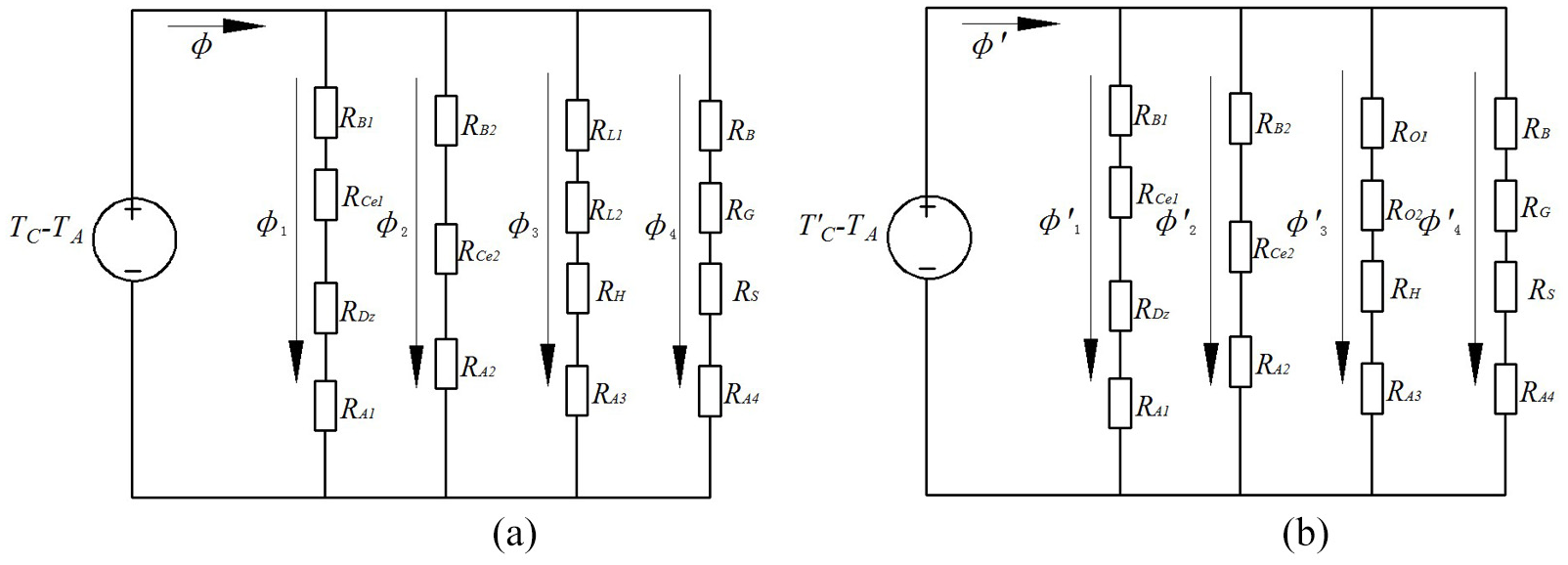
Equivalent thermal circuit model of the CGMA: (a) natural cooling and (b) oil cooling.
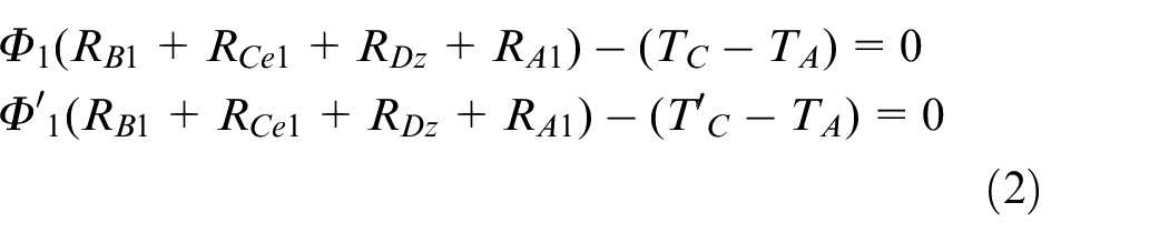
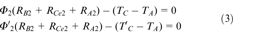
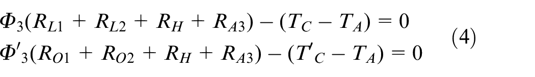
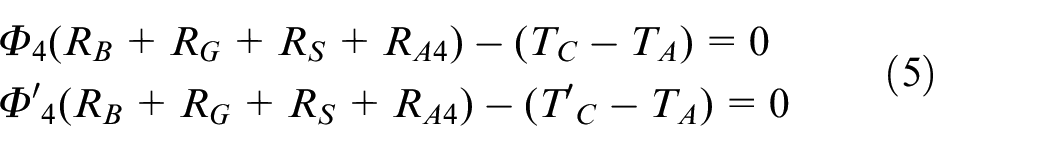
When the system is in steady-state heat transfer process, the heat transfer rate of each element is equal in the same thermal circuit. Based on Kirchhoff’s law and the loop analysis method in the circuit, the following equations under natural cooling and oil cooling are obtained
According to the above analysis, the eddy current loss and the hysteresis losses are ignored, as a result, the heat transfer rate is the Ohmic heat produced by the coil with drive current I and resistance R, and it can be expressed as:

The configuration of the main heat conduction components in the CGMA is cylindrical, so the heat conduction differential equation in the form of cylindrical coordinate system is as follows 24 :
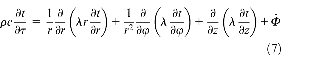
where
When the CGMA operates in DC, the mathematical model of steady-state heat transfer can be simplified as 1-dimensional steady state heat conduction with constant thermal conductivity. From simple deduction of equation (7) and the thermal resistance definition, the thermal resistances are obtained as in equation (8), in which RDz, RCe1, RCe2, RB2, and RB3 represent the thermal resistances of the base, the magnetic yoke 1, the magnetic yoke 2, the right coil bobbin and the left coil bobbin in axial direction, respectively; RH, RB, RG, and RS represent the thermal resistances of the housing, the coil bobbin, the CGMM and the sleeve in radial direction, respectively.
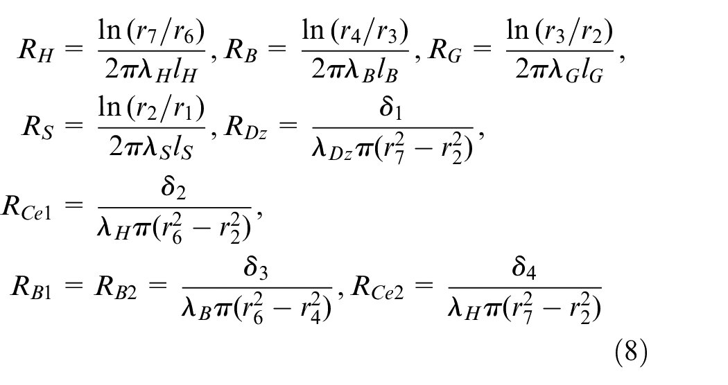
where λH, λB, λG, λS, and λDz are the thermal conductivities of the housing, the coil bobbin, the CGMM, the sleeve and the base, respectively; lH, lB, lG, and lS are the lengths of the cylindrical housing, the coil bobbin, the CGMM, and the sleeve, respectively; δ1, δ2, δ3, and δ4 are the thicknesses of the base, the magnetic yoke 1, the coil bobbin, and the magnetic yoke 2.
From the previous analysis, heat convection is another major form of the heat transfer in the CGMA. Natural convection in infinite space is the dominant factor in the heat transfer from the outer wall to the ambient air, and forced convection in enclosure is the dominant factor for the heat transfer from the drive coil to the cooling oil. From Newton’s law of cooling, the heat transfer rate of the convection

where h is the convective heat transfer coefficient,
In the heat convection, through simple deduction of equation (9) and the thermal resistance definition, the thermal resistances are obtained as follows
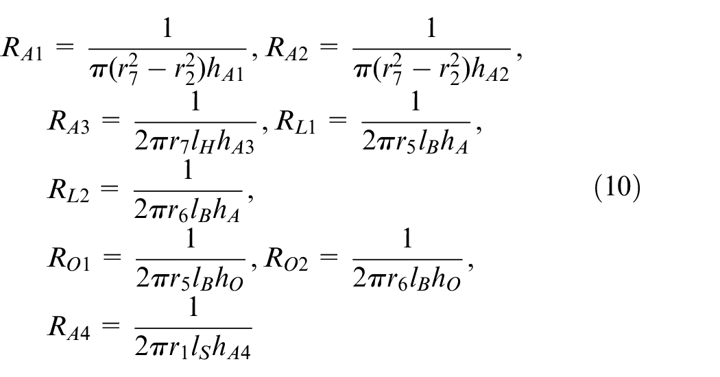
where RA1, RA2, RA3, and RA4 are the thermal resistances of the heat convection between the base and the ambient air, the head cover and the ambient air, the drive coil and the ambient air, the sleeve and the ambient air, respectively; RL1 and RL2 are the thermal resistances of the heat convection between the drive coil and the outer air, the housing and the inner air; RO1 and RO2 are the thermal resistances of the heat convection between the drive coil and the outer cooling oil, the housing and the inner cooling oil; hA is the natural convective heat transfer coefficient, and hO is the oil-cooling convective heat transfer coefficient. The equivalent resistance R1, R2, R3, R′3, and R4 in each branch heat pathway can be obtained by combining equations (8) and (10).
Based on simultaneous equations (1)–(6) and (11), the coil temperature under natural cooling
Coil temperatures under different cooling modes can be obtained by substituting equivalent resistances
Analogous to Ohm’s law in an electrical system, the following equations can be obtained as follows:
Based on simultaneous equations (1)–(6), (11), and (13), the temperature expression of the GMM
It can be seen from equations (11), (12), and (14) that the temperature of the drive coil or the CGMM in the steady state is determined by the material, the dimension and the convective heat transfer coefficient. The material and the dimension of each component in the CGMA have been fixed according to the magnetic field which determines the preload force value of the CGMA, and thus the cooling effect is mainly depends on the convective heat transfer coefficient.
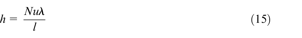
The convective heat transfer coefficient h can be calculated from equation (15), in which Nu is the Nusselt number and l is the characteristic length.
The heat transfer from the housing or sleeve to the ambient air is natural convection in infinite space and the contact area is transverse cylindrical surface. The experimental correlation formula of the Nusselt number can be written as follows:

where Pr is Prandtl number which is available in handbook; Gr is the Grashof number which can be obtained from equation (17).
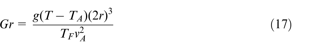
Where g is the gravitational acceleration, r is the radius of the housing or sleeve,
Based on simultaneous equations (15), (16), and (17), the expression for
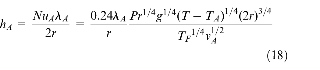
According to the formula (18), the natural convective heat transfer coefficient is determined by the structure size when the ambient temperature is constant, and thus, the convective heat transfer coefficient of cooling oil is the dominant factor to determine the heat dissipation effect when the CGMA with fixed size.
The heat transfer from the cooling cavity wall to the cooling oil is forced convection, and the convective heat transfer coefficient is also calculated from equation (15), in which the Nusselt number should be obtained firstly because it has different experimental correlation formula under different flow patterns. The most primary flow is judged by the Reynolds number calculated from equation (19).
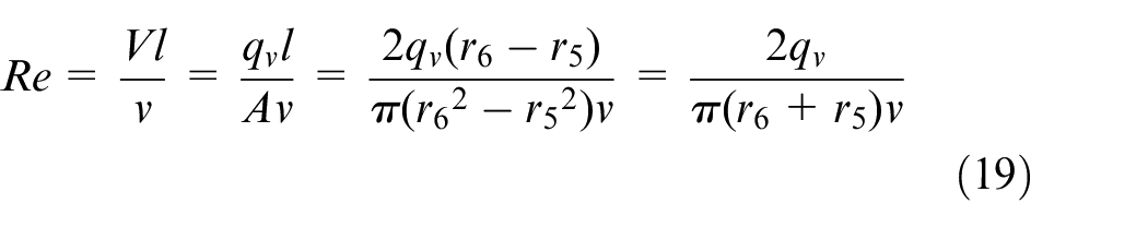
where Re is the Reynolds number, V is the flow velocity, v is the oil viscosity,

Based on simultaneous equations (15) and (17), the oil-cooling convective heat transfer coefficient hO can be written as follows:
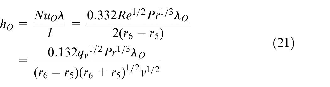
It can be seen from equation (21) that the convective heat transfer coefficient is determined by the flow velocity of when the physical parameters of the cooling oil are fixed, namely, the flow velocity determines the cooling effect.
Thermal expansion displacement model of CGMM
The CGMM, which is the core component of CGMA, will generate thermal deformation when its temperature increases. Moreover, the thermal expansion displacement of CGMM is the main factor of the thermal displacement error. Accordingly, it is necessary to analyze thermal displacement model of CGMM for thermal displacement control of CGMA.
For the CGMM with one end fixed and the other end free, its thermal expansion deformation is as follows 14 :
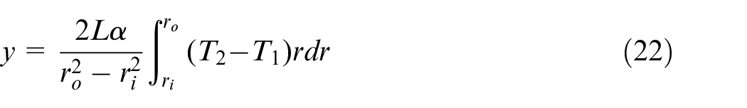
where L is the length of the CGMM, α is the thermal expansion coefficient of the CGMM, ro and r i are the outer diameter and inner diameter of the CGMM, and T1, T2 are the temperature of the CGMM before and after thermal expansion.
Based on simultaneous equations (14) and (22), the thermal expansion displacement of CGMM under natural cooling and forced oil cooling can be written as follows:
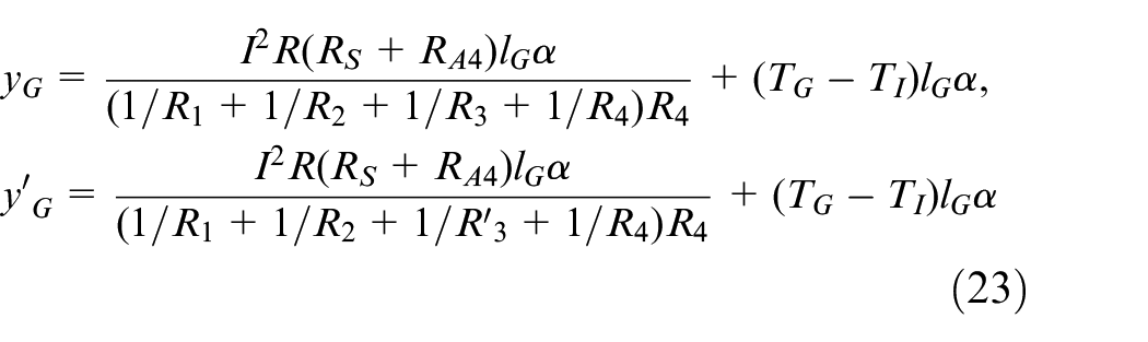
It can be seen from the above analysis that the factors, which affect the cooling effect of the CGMA’s temperature control system, can be quickly and simply determined by the thermal circuit model obtained from the loop analysis method. And the thermal circuit model can be used to analyze the influence of each factor on the temperature qualitatively. Since the model is established with neglecting several small components such as disc spring, output rod and bolts, the accuracy of quantitative analysis results is naturally poor. To accurately analyze the heat effect from the drive coil on the temperature field and thermal expansion displacement, the finite element analysis software ANSYS Workbench is adopted as well as used to discuss the cooling effect and select the parameters of the cooling oil.
Simulation results analysis
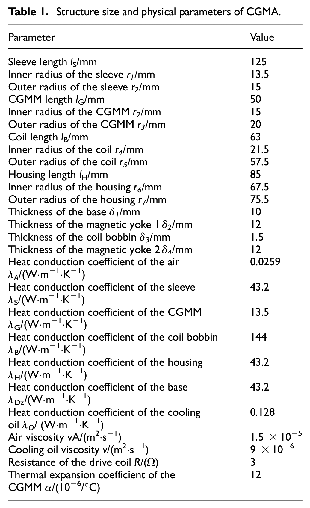
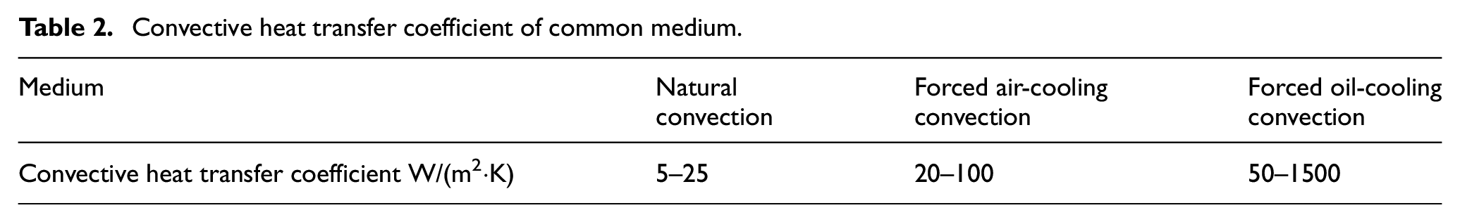
Taking application, cost, magnetic circuit, and output characteristic into consideration, the main size and material as well as physical parameters of the CGMA are described in Table 1. Firstly, a 3D model is developed in ANSYS Workbench15 based on the structure in Figure 2 and the parameters in Table 1. Next, the boundary conditions are set. The resistance of the driving coil is 3 Ω, and the driving current changes from 0 A to 5 A, so the heating power under 5 A driving current is 75 W calculated from equation (6). Load this heating power to static thermal module in ANSYS Workbench15. Without cooling oil, there is only heat exchange between the ambient air and the CGMA. As shown in Table 2, the natural convective heat transfer coefficient is 5∼25 W/(m2*K). The ambient temperature is set to 30°C, and the simulated temperature field with 15 W/(m2*K) is shown in Figure 5 after calculation.
Structure size and physical parameters of CGMA.
Convective heat transfer coefficient of common medium.
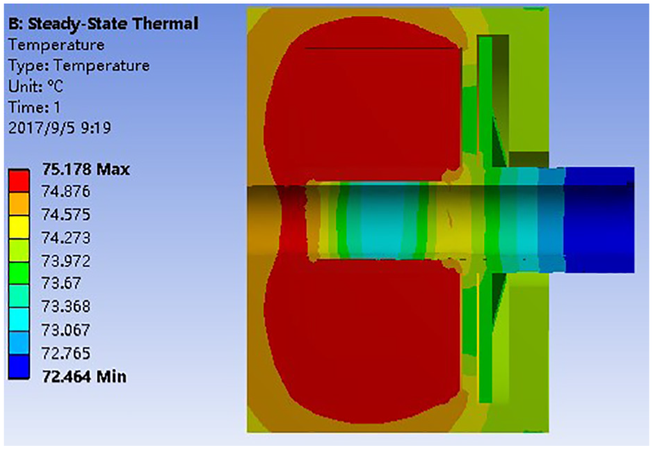
Temperature field of the CGMA without cooling measures.
Without cooling measures, the highest temperature of the drive coil reaches 75.18°C and that of the CGMM also reaches 74°C as shown in Figure 5. Refer to the literatures Zhou et al. and Kwak et al.,16,17 the CGMM has stable magnetostrictive characteristics when the temperature is between 40°C and 50°C. Thus a cooling method should be developed to control the temperature in an optimal range in the application.
Based on the temperature control structure of the CGMA in section 2.1, the cooling effects with the three methods of natural cooling, forced air cooling and forced oil cooling are studied. According to the Table 2, the convective heat transfer coefficients 15 W/(m2·K), 50 W/(m2·K), and 500 W/(m2·K) of the three method are selected in the simulation. It is assumed that the ambient temperature as well as the temperature in the cooling cavity is 30°C, and the drive current changes from 0 A to 5 A. When the CGMA is in the steady state, the simulation results of the CGMM temperature is shown in Figure 6(a), and the thermal expansion displacements calculated from equation (23) is shown in Figure 6(b). It is obvious that the cooling effect of forced convection is better than that of natural convection as shown in Figure 6(a). When the drive current changes in the range of 0∼5 A, the temperature difference is more than 25°C under forced air cooling but less than 5°C under forced oil cooling. As shown in Figure 6(b), when the drive current is 5 A, the thermal expansion displacement will reach up to 27 μm under natural convection and 17 μm under forced air cooling, but only 3 μm under forced oil cooling. The results clearly indicates that the excellent cooling effect in the CGMA is produced by the forced oil-cooling method, and thus, the error caused by thermal expansion can be effectively suppressed. It can be easily seen from Figure 6 that the CGMM temperature is below 40°C when the coil temperature is 30°C. To make the temperature be in an expected range (40°C–50°C), an optimization analysis of the oil temperature in the cooling cavity is required.
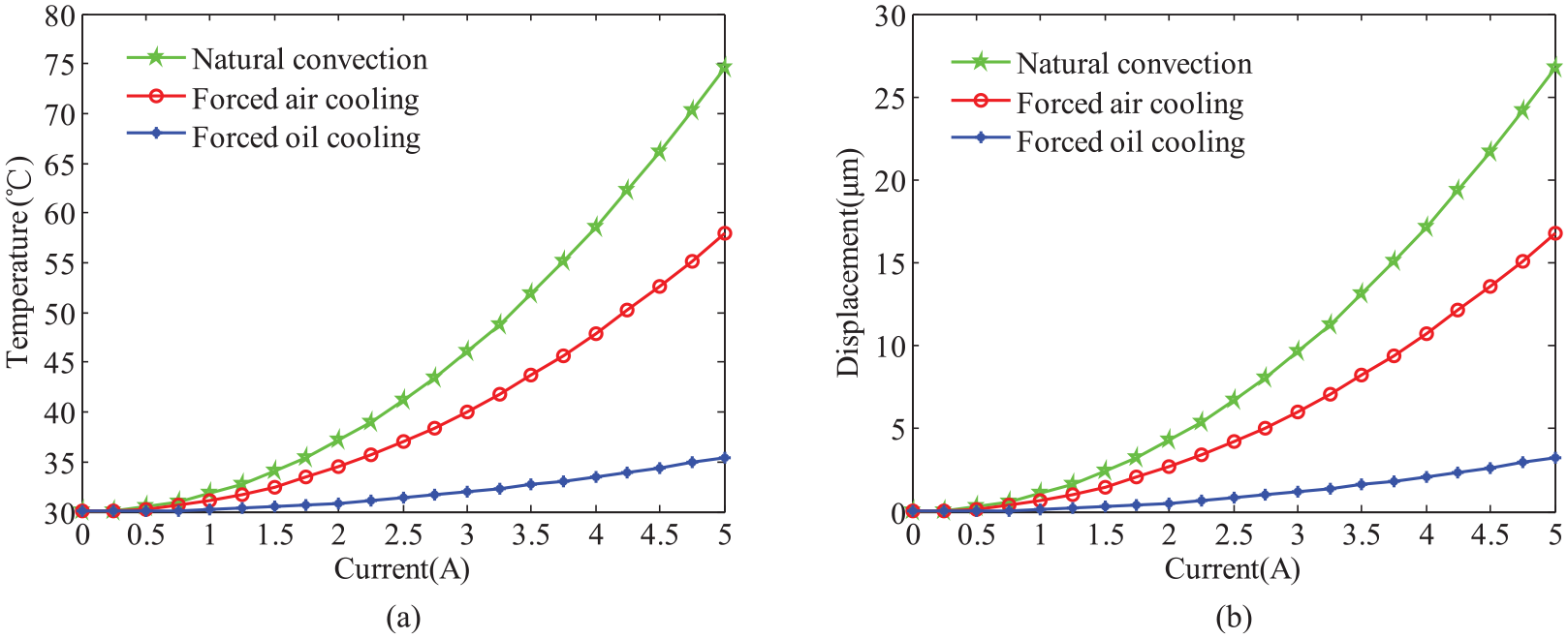
CGMM temperature and thermal expansion displacement with different cooling method: (a) temperature and (b) thermal expansion displacement.
The convective heat transfer coefficient 500 W/(m2·K) and the ambient temperature 30°C are selected; the circulating oil in cooling cavity with temperature 30°C, 35°C, 40°C, 45°C, and 50°C results in different CGMM temperature as shown in Figure 7(a). It can be seen from Figure 7(a) that the CGMM temperature is in the range 40°C–50°C when the oil temperature changes from 40°C to 45°C, so the oil temperature 43.5°C is determined. Figure 7(b) shows that the change curves of thermal expansion displacement at different oil temperatures are in good agreement, which indicates that the oil temperature has little influence on the change trend of thermal expansion displacement under forced oil cooling.
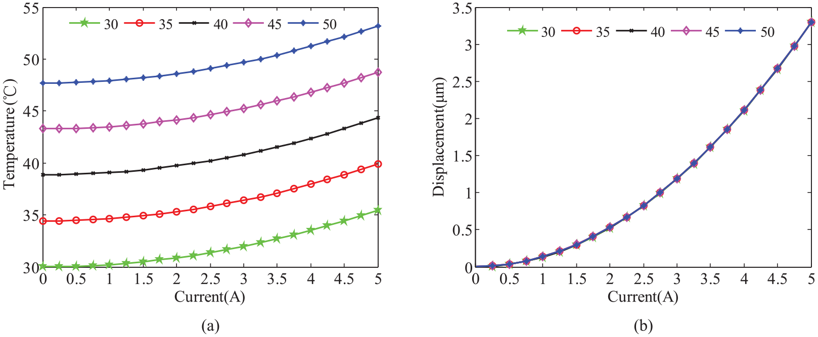
CGMM temperature and thermal expansion displacement at different oil temperature: (a) temperature and (b) thermal expansion displacement.
As analyzed in section 3.1, the convective heat transfer coefficient is an dominant factor affecting the cooling effect. So as to identify the specific value of the convective heat transfer coefficient, its influences on the temperature field distribution of the CGMA and thermal expansion displacement change of the CGMM are discussed. The simulation conditions and parameters are as follows: the oil temperature is 43.5°C, the drive current is 5 A, the convective heat transfer coefficient changes in the range 50∼1500 W/(m2·K). Figure 8(a) shows the calculated temperature distribution in the CGMA and Figure 8(b) shows the relationship between the difference, which is between the maximum temperature and the minimum value, and the convective heat transfer coefficient. It is clear that the temperature and its difference decrease with the increase of convective heat transfer coefficient, which indicates that the cooling effect is sensitive to the convective heat transfer coefficient, and the larger the convective heat transfer coefficient is the more uniform the temperature distribution is. Similarly, the oil temperature remains unchanged, the range of convective heat transfer coefficient keeps the same. The temperature and thermal displacement of the CGMM under different current are shown in Figure 9. It can be seen from Figure 9, when the convective heat transfer coefficient is greater than 450 W/(m2·K), the steady-state temperature of the CGMM will be in the range 40°C–50°C even though under different drive current. Considering the pump power and flow velocity in the actual application, the convective heat transfer coefficient 480 W/(m2·K) corresponding to the flow velocity 50 L/min of the cooling oil is selected after repeated optimization combining with equation (20).
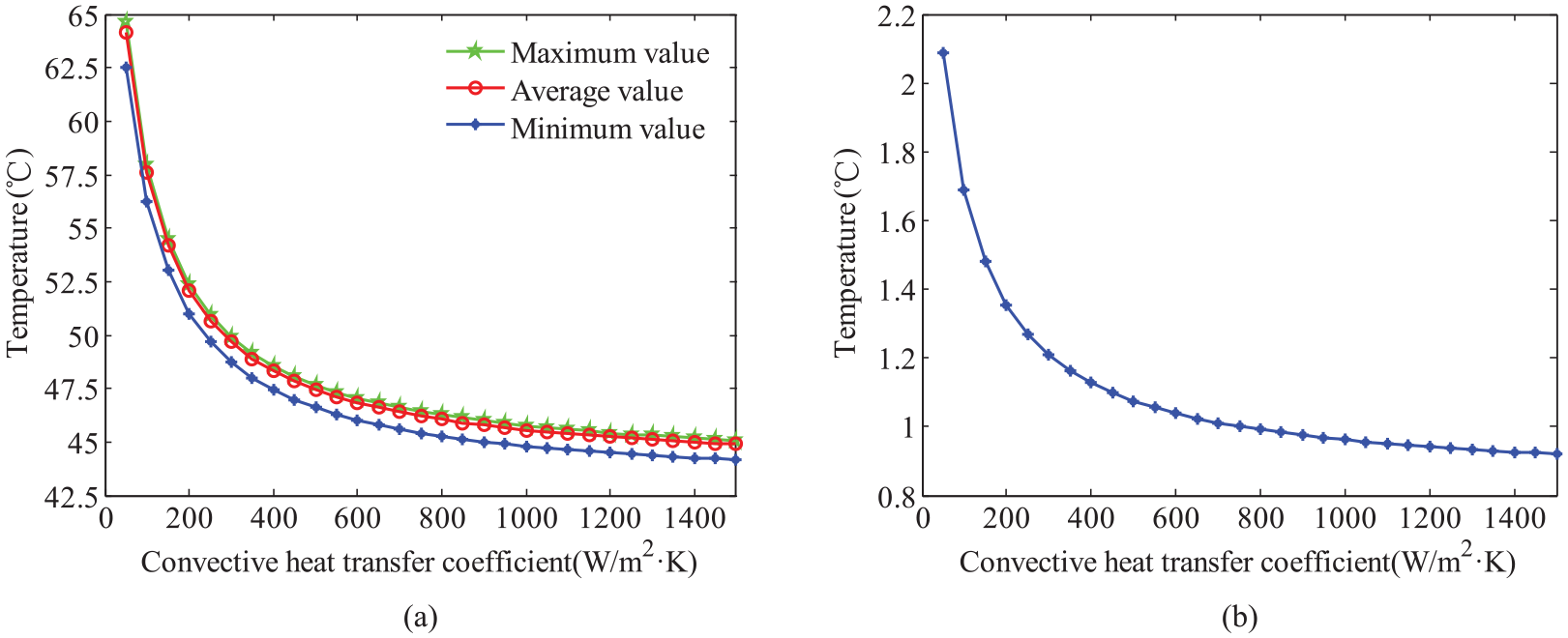
Effect of convective heat transfer coefficient on temperature distribution of the CGMA: (a) temperature and (b) temperature difference.
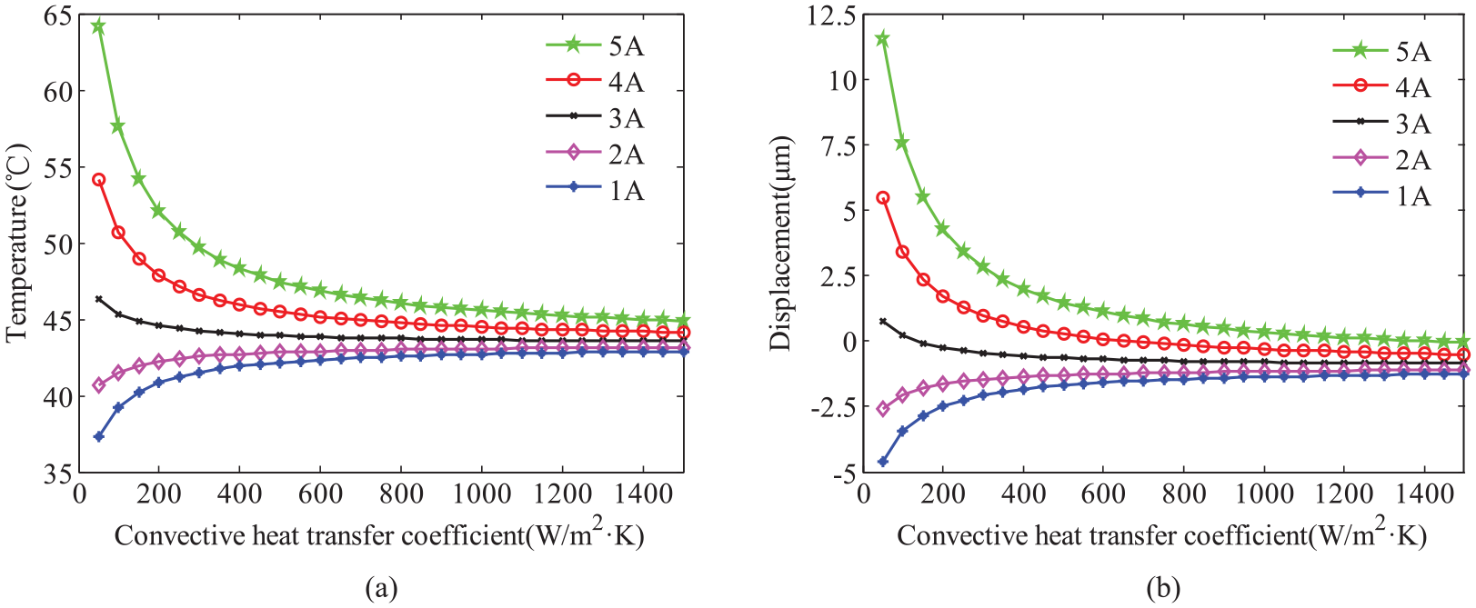
CGMM temperature and thermal expansion displacement under different convective heat transfer coefficient: (a) temperature and (b) thermal expansion displacement.
From the analysis of the thermal circuit model, it is concluded that the temperature and flow velocity of the cooling oil are the main factors influencing the cooling effect in the case of a fixed structure size. Based on the conclusion, the parameters which make the CGMA work in an ideal temperature range are determined by using the finite element simulation. The optimization method combining the thermal circuit analysis with the finite element simulation can save a lot of calculation work, which provides a new approach for the design of CGMA temperature control system.
Experimental results analysis
The prototype of the CGMA is developed according to the parameters as described in Table 1 and the thermal characteristics test system is established as shown in Figure 10. The CGMM temperature is measured by using a thermocouple and a digital thermometer, the output displacement of the CGMA is measured by using a laser displacement sensor, the collected signal is converted to digital form and transferred to the PC by the data acquisition module, the digital control current source provides automatically adjusting current for the CGMA. In this system, a forced oil cooling method is used to reduce the temperature, that is, the active temperature control of the CGMA is achieved by the circulating oil supplied by the pump. Such cooling method not only ensures the stability of the magnetostrictive coefficient but also suppresses the thermal deformation error caused by the temperature rise.
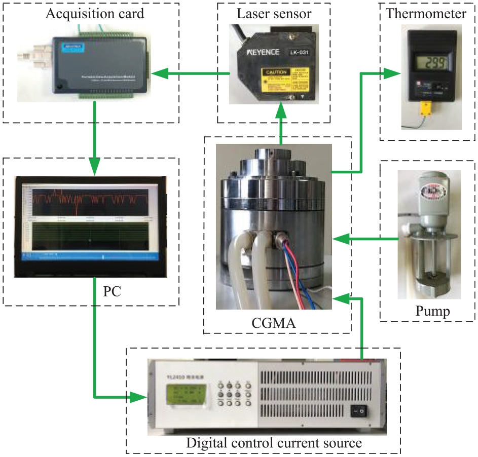
Thermal characteristics test system of the CGMA.
Experimental investigation under natural cooling
To disclose the thermal characteristics of the CGMA under natural cooling, the temperature and the thermal displacement were respectively measured every half a minute with given current value 3 A, 4 A, and 5 A. As shown in Figure 11, the temperature and the thermal displacement increase continuously with time within 60 min, and the greater the current value, the faster the temperature and displacement increase with time. When the drive current is 3 A, the CGMA tends to be in steady-state heat transfer process after 60 min, and the temperature is about 43.6°C which is close to the simulation result 46.01°C in Figure 6(a). When the drive current is 5 A, the temperature is over 70°C as well as the displacement over 19 μm after 60 min. Comparing Figure 11(a) and (b), the temperature versus time and the thermal displacement versus time have the same change trend, but, the temperature is not proportional to the thermal displacement. The main reason is that the temperature rise not only affects the thermal expansion displacement of the CGMA but causes change in magnetostrictive displacement.
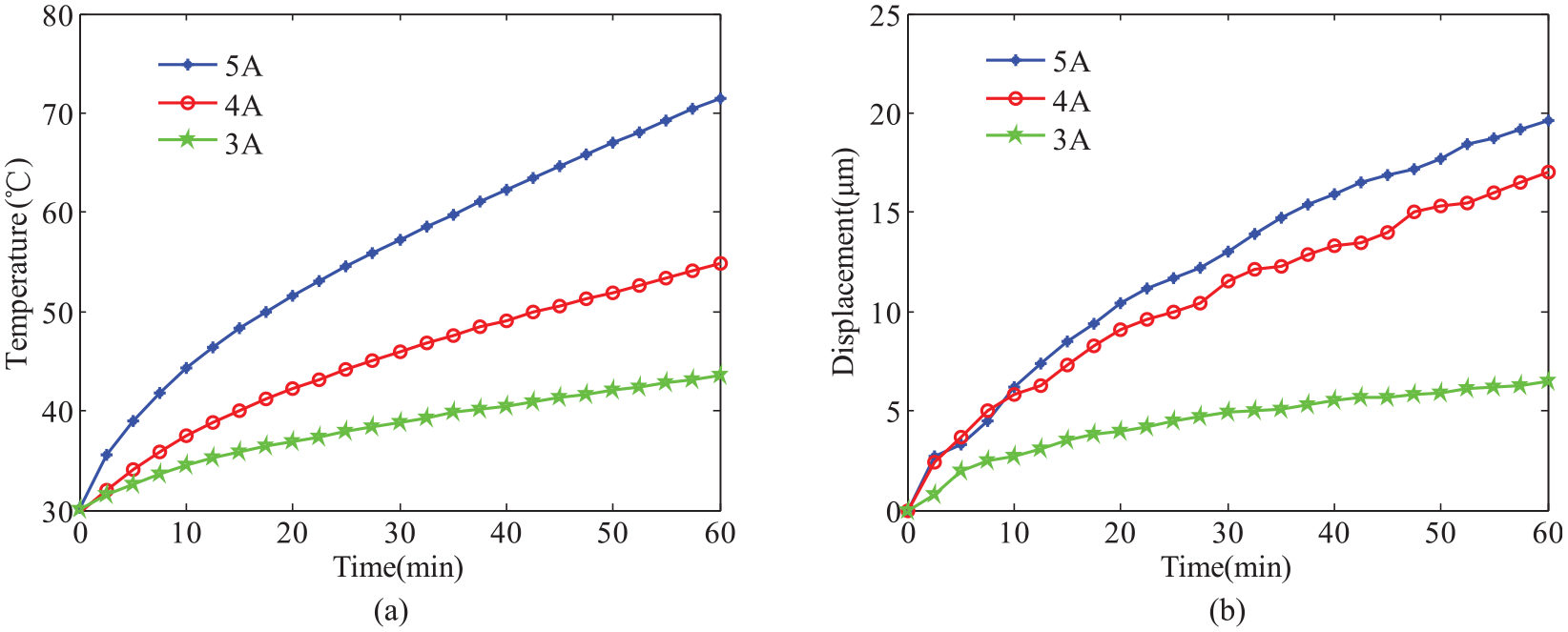
Thermal characteristics test of the CGMA under natural cooling: (a) temperature and (b) thermal displacement.
To disclose the temperature effect on magnetostrictive characteristics, the output magnetostrictive displacements of the CGMA at different temperatures were measured. Under natural cooling, the initial temperatures in the CGMA are respectively 33.5°C, 43.5°C, and 53.5°C, the input current circularly changing from 0 A to 5 A results in the magnetostrictive displacement Y1, Y2, and Y3 responses as shown in Figure 12(a). The magnetostrictive displacement differences in the current increase and decrease process are shown in Figure 12(b). It can be seen from Figure 12(a), under the action of the same current, the output magnetostrictive displacement becomes larger along with the rise of temperature, but the whole curves at different temperatures have similar output characteristics. It can be seen from Figure 12(b) that the output displacement differences under the same temperature difference are not consistent, which once again indicates that the temperature rise affects the thermal expansion displacement as well as the magnetostrictive displacement.
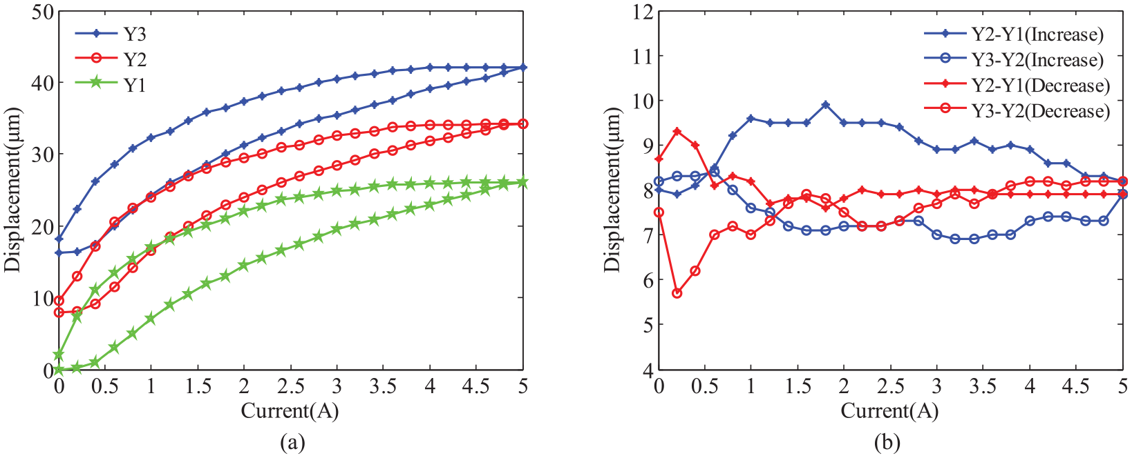
The temperature effect on magnetostrictive displacement of the CGMA: (a) magnetostrictive displacement and (b) magnetostrictive displacement difference.
It can be concluded from the experimental results that the temperature of the CGMA will be over 70°C under action of the drive coil without cooling measures, the temperature rise will introduce the thermal deformation error and affect the magnetostrictive characteristics of the material to make the output unstable, in addition, the temperature rise will cause performance degradation of the double-nut ball screw in application. Therefore, the forced cooling measures must be taken to reduce the temperature effect on output characteristics of the CGMA.
Experimental investigation under forced oil cooling
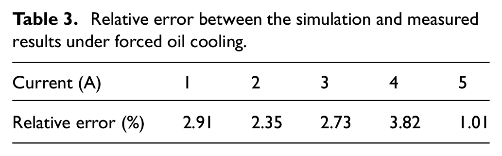
Considering the application of the CGMA, the forced oil cooling method which directly cools the drive coil is employed in the temperature control system. Based on the optimization method combining the thermal circuit analysis with the finite element simulation in section 4, the oil temperature 43.5°C and follow velocity 50 L/min are adopted in the test. To verify the rationality of the optimization method for temperature control system parameters, the test under forced oil cooling is performed. In steady-state heat transfer process, the simulation and measured results of the temperature with different drive current are shown in Figure 13 and the relative errors between them as shown in Table 3. Obviously, under forced oil cooling, the measured temperature has good agreement with the simulation ones and the relative errors under the action of different input current are below 5%. Moreover, the temperature of the CGMA is in a stable operating temperature range 40°C–50°C. However, there is still some error between them and the simulation values are higher than the measured ones, the main reason of which is that small components such as the disc spring, the bolts and etc. are ignored in the finite element simulation analysis.
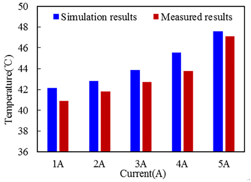
Comparison between the simulation and measured results under forced oil cooling.
Relative error between the simulation and measured results under forced oil cooling.
The test of magnetostrictive displacement under the natural cooling as well as the forced oil cooling was carried out to verify the cooling effect. When the driving current changes in the three ranges of 0 A∼3 A, 0 A∼4 A, and 0 A∼5 A, the measured output displacements are shown in Figure 14(a) and (b), the displacement differences in the current increase and decrease operations are respectively shown in Figure 14(c) and (d). As shown in Figure 14(a), the three output characteristic curves are not consistent in the process of current increase and the hysteresis errors are different and large when the current returns to the zero point, which clearly indicate that the magnetostrictive and hysteresis characteristics of the CGMA are unstable without cooling measures. However, as shown in Figure 14(b), the output characteristic curves of magnetostrictive displacement are in good agreement and the errors are close and small at the zero point of return under the forced oil cooling. As shown in Figure 14(c) and (d), the larger the current is, the greater the output displacement difference of the two cooling methods is, but, the differences are not regular by comparing them corresponding to the current increase and decrease since the temperature rise has an effect on the thermal expansion displacement as well as the magnetostrictive displacement.
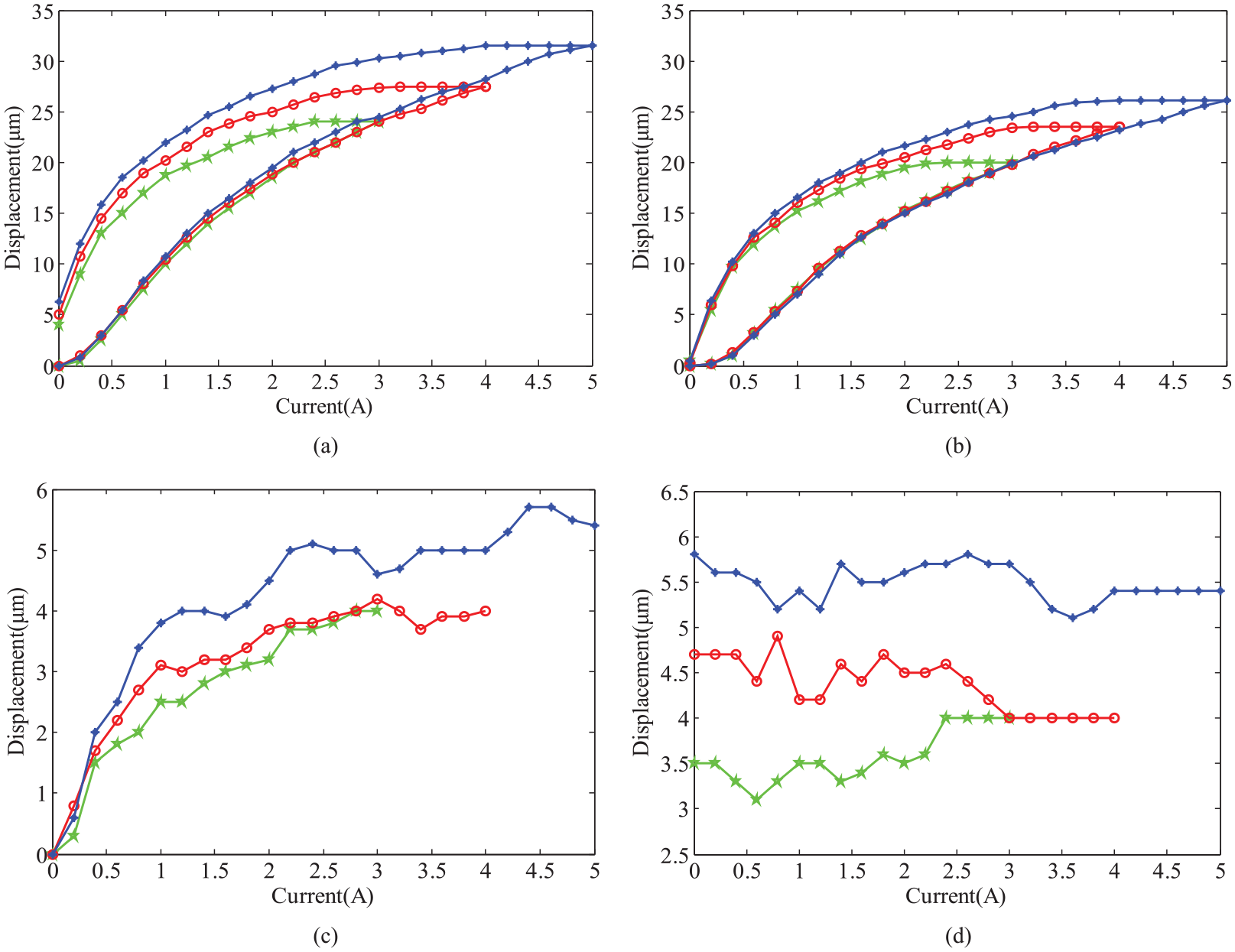
Comparison between measured displacements under natural cooling and forced oil cooling: (a) output displacements under natural cooling, (b) output displacements under forced oil cooling, (c) difference in the current increase, and (d) difference in the current decrease.
The experimental results indicate that it is reasonable to optimize the parameters of temperature control system using the thermal circuit and finite element analysis, the oil cooling method which directly cools the heat source has an excellent cooling effect, furthermore, the CGMA under forced oil cooling has stable characteristics and a proper operating temperature for double-nut ball screw preload.
Conclusion
Based on the structure of the preload system for double-nut ball screw, a CGMA is developed with an oil-cooling temperature control system which directly cools the heat source. Such forced oil-cooling method can effectively suppress the thermal error and improve the output accuracy and stability of the CGMA.
To investigate the heat transfer characteristics of the CGMA, the heat transfer model and the thermal circuit model are established under natural convection and forced oil cooling. According to the steady-state temperature model obtained from loop analysis method in thermal circuit, it is concluded that the temperature and flow velocity of the cooling oil are the main factors influencing the cooling effect of the CGMA with a fixed size. And then the oil temperature 43.5°C and follow velocity 50 L/min, which make the temperature control system work effectively, are determined by using the finite element simulation. The optimization method combining the thermal circuit analysis with the finite element simulation provides a simple way for parameter selection of the temperature control system.
The thermal characteristics test system of the CGMA was established, and an experimental investigation under natural convection and forced oil cooling was performed. The experimental results show that the CGMA temperature can be controlled in an ideal temperature range (40°C–50°C) with the oil temperature 43.5°C and follow velocity 50 L/min. Under forced oil cooling, the relative error between the measured temperatures and the simulation values is less than 5%, which proves the rationality of the temperature control system. Furthermore, the output accuracy and stability of the magnetostrictive displacement is improved with oil cooling method which ensure the feasibility of the CGMA for ball screw preload.
The research results provide a basis for the application of CGMA in the precise adjustment of double-nut ball screw preload. In this paper, the cooling effect of the CGMA temperature control system is mainly discussed. There is little research on the temperature coupling relationship between the double-nut ball screw and the CGMA. In order to accelerate the practical application of oil-cooling temperature control system in the preload system for double-nut ball screw, our upcoming research will focus on the temperature coupling relationship. In addition, the optimal value of the convective heat transfer coefficient is obtained through multiple simulation experiments. In the next step, the optimization algorithm will be considered to improve the accuracy and efficiency of the convective heat transfer coefficient.
Footnotes
Appendix 1
Declaration of conflicting interests
The author(s) declared no potential conflicts of interest with respect to the research, authorship, and/or publication of this article.
Funding
The author(s) disclosed receipt of the following financial support for the research, authorship, and/or publication of this article: This work is supported by the National Natural Science Foundation of China (No. 51475267).