
Abstract
Powder bed fusion (PBF) is one of the most popular techniques in additive manufacturing (AM). The PBF technique of selective laser melting (SLM) consolidates powder layer by layer using a laser as the energy source. This technique ensures the processes capability of fabricating components with internal and external complex geometries, which could be challenging to make with conventional manufacturing methods. However, the cyclic heating and cooling inherent in this process give rise to the buildup of residual stresses, which can distort or completely deform the part. In this work, a screening build with nine factors was designed to investigate the effects of component size, support structure, and energy input on the build completion and average distortion induced by the inherent residual stress. Experimental results indicated that support hatch spacing, part thickness, and support contact spacing played dominant roles in the final quality (i.e. resultant deformation) of the built parts. The identified significant factors from this study can be carefully selected to increase the success rates of single builds and improve the qualities (i.e. geometric accuracy) of the final products.
Introduction
Additive manufacturing (AM) consolidates a component layer by layer with an energy source to selectively melt materials. The nature of this layer-wise manufacturing process enables the fabrication of the components with complex geometries with less assembling or machining, which is quite challenging, or impossible, to achieve with conventional subtractive manufacturing methods. However, defects impede the broad adoption of AM, 1 such as the introductions of porosity,2–6 distortion,7–9 and residual stress.10–13 These defects could worsen the geometric accuracy, surface roughness, and mechanical property (e.g. fatigue life 14 ). One of the potential causes of the introduction of those defects could be improper sets of build process parameters. According to the porosity creation mechanism, four melting zones could be defined with varying laser powers and scan speeds,15,16 including a fully dense zone, over melting zone, incomplete melting zone, and overheating zone. In most cases, the fully dense zone is most desired. At the same time, the optimal parameter combinations need to be tested out, and the final parts require to be characterized to demonstrate the applicability and performance. In most laser PBF system, process parameter is a combination of laser power, scan speed, hatch spacing, and layer thickness. Energy density,4,6,15,17 which is defined in equation (1), is widely accepted and can represent the combination of the effects of those parameters.
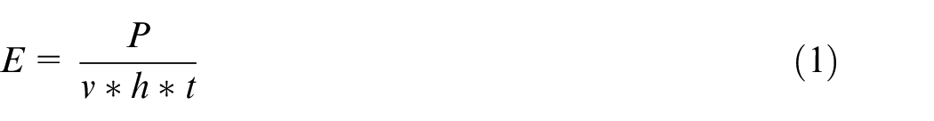
where
The inherent heating and cooling cycles in the building process lead to the accumulations of residual stresses, which can be explained by the temperature gradient mechanism model and the cool-down phase model. 20 Hence, a sacrificial support structure is needed under the un-supported area to both dissipate the heat generated and keep the part staying in position from distortion induced by the residual stress. The selection of sacrificial support structures can also be responsible for defect generation, especially the issues of geometry inaccuracy due to distortion and warping. The work presented by Cooke and Soons reported the geometric errors of AM test parts were usually more severe than the conventional machined part by at least an order of magnitude. The thermal effects of the AM process and post heat treatment were significant to the geometric accuracy of the printed part, especially the part with a high aspect ratio (e.g. thin-walled parts). 21 These part errors can also be mitigated by using a larger volume of the support structure, which provides higher strengths. However, material cost, build time, and support removal are also significant factors to be taken into consideration. Many research efforts contribute to tailoring the support structures for saving material and removing easiness while keeping sufficient strengths from cracking and warping induced by the residual stress due to the rapid solidification rate of the PBF system. The geometries and the corresponding parameters of support structures are essential for fighting against the residual stress.22,23 Cellular lattice structure was one of the popular support structures adopted in SLM.24–26 Hussein et al. 24 developed two types of lattice support structures naming diamond and gyroid. They varied the volume fraction and cell size of the cellular support to reduce the build time and machine easiness. A minimum of 8% volume could be successfully manufactured. They also pointed out that there was a tradeoff between the build cost and the thermal, mechanical performance of the support structure to constrain deformation. Yan et al. 26 evaluated manufacturability, density, and compression properties of the SLM-printed cellular lattice structures with varying unit cell sizes. Researchers also applied other types of support structures. Bobbio et al. characterized the strength of block types support structures to tailor the strength of the support structure geometry to the minimum needed supports. It was demonstrated that their effective structural strength was 14% to 32% of the strength of fully dense material. 27 Poyraz et al. 28 investigated the effect of block type support parameters including hatch distance, fragmentation interval, top length, and z offset on the distortion of the parts and concluded hatching parameters had a more significant effect than the teeth parameters. The minimum point support structures, 29 “Y,”“IY,” and pin support structure 30 were also applied in the SLM process to balance a tradeoff between the build consumption and the effectiveness and easiness of removal of the designed support structure. Other factors, including part geometry like chord height tolerance and diameter of holes, 31 part placement, 32 post-machining condition, 33 were also proposed to influence the quality of the final products by affecting geometric accuracy and inherent residual stress.
A full factorial experiment could be designed to reveal the impact of all potential effects and their interactions on the deformation of the build parts. However, it is impractical to implement all the full factorial experiment runs, considering the high cost for both feedstock and build time. Screening design can identify significant main effects of factors out of many potential ones with few considerations of interaction between factors. In this study, nine factors, including aspect ratio, scale, thickness, support contact length, support contact spacing, support hatching spacing, energy input, contour support, and support thickness, in terms of part’s dimension, energy density, and support structure geometries and parameters were considered to be the potential factors affecting the geometry accuracy by introducing deformation of built parts. A screening design generated by Minitab 18 was then employed to minimize the required number of experiment runs. Part completion and average corner distortion were evaluated as response variables to quantify the build quality of the parts. The experimental method used to measure the distortions of the built blocks were detailed in the Materials and Methods section. In the Result and Discussion section, the measured deformations were gathered, and normal probability plots and Pareto charts were applied to assess the significance of each factor in terms of response variables.
Materials and methods
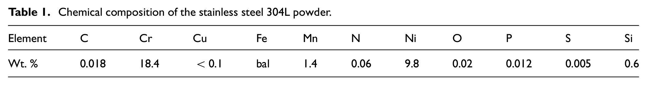
The material used for this research was Argon gas-atomized stainless steel 304L purchased from LPW Technology with a size distribution ranging from 15 µm to 45 µm. The chemical composition of the powder provided by the vendor is tabulated in Table 1. Renishaw AM 250, located at Missouri University of Science and Technology, was employed to fabricate the parts. The machine was equipped with an Nd-YAG pulsed laser (Gaussian intensity profile), producing a peak power of 200 W. A preheating temperature was set on the substrate and distributed powder particles at 80°C to reduce the effect of water content inside the powder. The oxygen level was monitored by sensors to be maintained below 1000 ppm during the whole building process.
Chemical composition of the stainless steel 304L powder.
For the ease of building process, rectangle blocks assigned with different dimensions were fabricated in this study. A stripe scan strategy for path planning was applied. All of the support structures which were used underneath the built blocks were saw-tooth support structures. Nine specific factors utilized in this screening design are interpreted as following, and part of those are illustrated in Figure 1.
Aspect ratio (AR): the ratio of the length to width of the parts
Scale (Sc): multiplication factor used to determine physical dimensions from the aspect ratio
Thickness (Th): the thickness of the parts
Support contact length (SCL): length of contact between saw-tooth and the part
Support contact spacing (SCS): spacing between the saw-tooth at the part support interface
Support hatch spacing (SHS): spacing interval of the grid structure
Energy input (EI): energy density used to define the scan speed
Contour support (CS): line of the supports along the perimeter of the part
Support Thickness (STh): the thickness of the supports
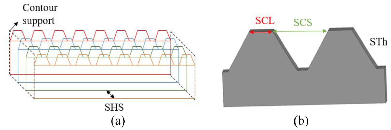
The illustration of parameters with (a) contour support and support hatch spacing and (b) support contact length, spacing, and thickness.
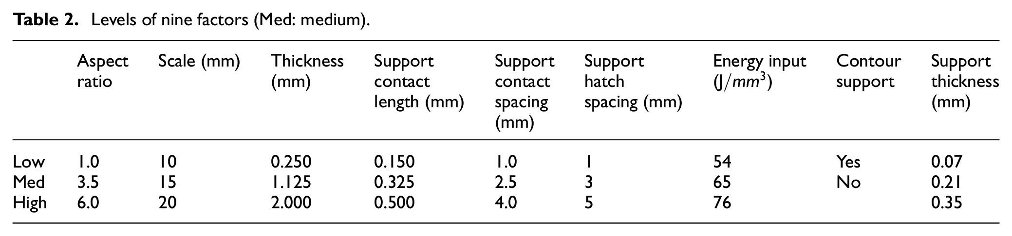
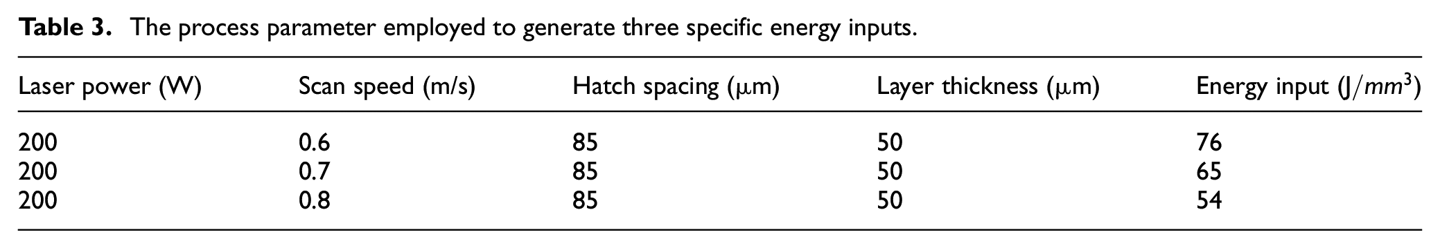
Each factor was drastically varied, resulting in three levels, except for contour support, which was a binary either the presence or absence of contour supports. The various levels used for each of the factors are tabulated in Table 2. The heights of all of the supports were set to be 10 mm to indicate the effect of support structures. To generate the various EIs, three different scan speeds were selected with the constant laser power, hatch spacing, and layer thickness, as listed in Table 3. Using equation (1), the three different EIs needed for the experiment were also determined.
Levels of nine factors (Med: medium).
The process parameter employed to generate three specific energy inputs.
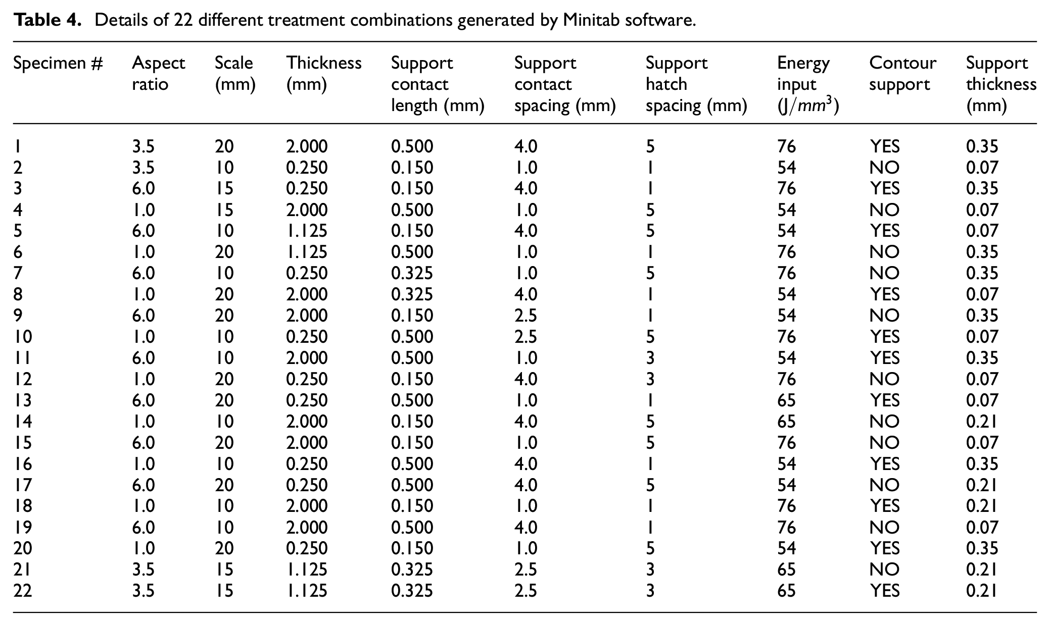
The screening design with nine factors was generated using Minitab 18 software and resulted in requiring 22 different treatment combinations to reveal the main effect with randomization. The corresponding parameter sets were listed in Table 4. No replications were utilized. Ideally, no build to build variation was assumed. The build plate layout generated by Materialize Magics is shown in Figure 2, where a 45-degree build orientation in the x-y plane was assigned to reduce the force from the interaction between parts and wiper. 34 The specimen numbers labeled on the top surface of the parts corresponded to the specimen numbers in Table 4.
Details of 22 different treatment combinations generated by Minitab software.
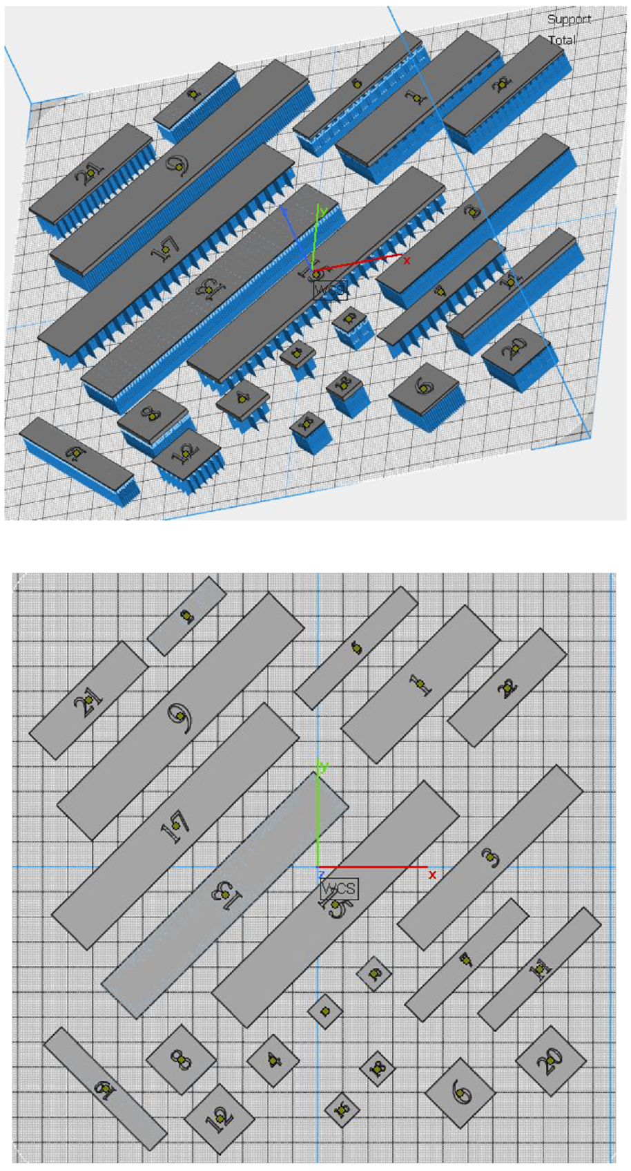
A building layout of 22 specimens with the wiper direction from top to bottom.
For the purpose of evaluation of the specimens fabricated, three criteria were selected, part completion for the success rate of the builds, corner distortion while attached to the build plate where the distortion on corner/edge of the parts represented the maximum value of deformation, and edge displacement after being released from the build plate. Part completion was simply assigned a 1 indicating a part build successfully and 0 indicating a part failed to build. The second response variable, corner distortion, while attached to the build plate, is shown in Figure 3. Prior to the removal of the built parts from the substrate, the height of each part was measured at the highest point at each of the four corners using a height gauge with a resolution of 0.0001 mm. The measured heights at four corners were averaged to represent the mean height of the part, which was then subtracted by the designed (ideal) height. Then, the distortion of each part can be expressed as equation (2):

where
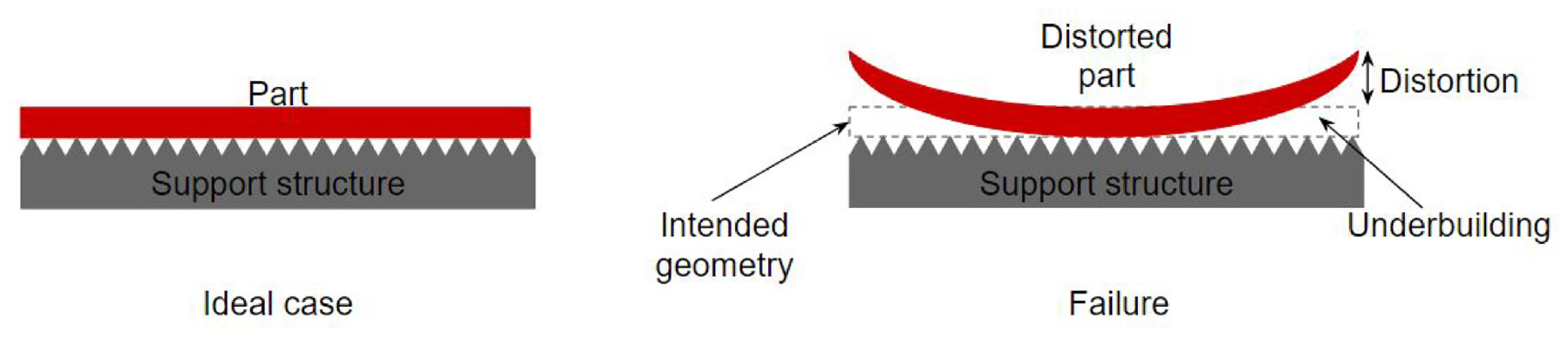
The illustration of the distortion of parts at the corners.
The same height measurement was repeated after all parts were removed from the substrate using wire EDM. Comparing these measurements to the previous measurements resulted in the last response variable, defined by equation (3), which was the displacement of the edge after removing from the substrate. This displacement was a result of releasing internal residual stress during wire EDM cutting:

where
Result and discussion
Due to an unpredictable build failure for the first time, two builds had to be fabricated, which are shown in Figure 4(a) (first build) and (b) (second build). In the first build, specimens highlighted with A, B, and C (shown in Figure 4(c)) had massive distortions at the corners, which interacted and impeded the motion of wiper, hence the build was stopped. The yellow boxes highlighted in Figure 4(a) revealed the evidence of the damage of the silicone on the wiper, which affected the powder spreading; hence extra powder particles were melted and solidified along the damaged tracks inducing humping on the part surface. By this point in the build, several of the specimens had already finished building. However, some had not due to the difference in part thickness. A duplicate second build had to be fabricated to complete the rest of the specimens, which were prematurely terminated due to the wiper failure.
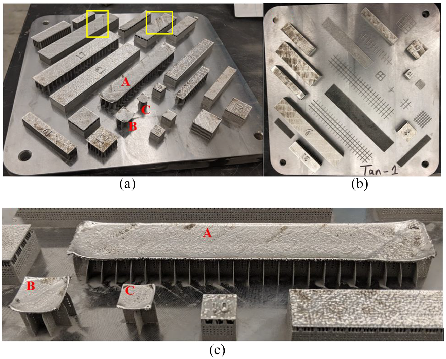
The finished built specimens with (a) from the first build, (b) from the second build, and (c) the zoom-in image of the three failed parts.
For all the responses, normal probability plots and Pareto charts were generated using Minitab 18 with a 90% confidence level to determine the magnitude, direction, and significance of the effects and present the absolute values of standardized effect. The standardized effects are based on testing the null hypothesis, where the effect is 0. In normal probability plots (Figures 5(a), 6(a), and 7(a)), the red markers represent factors with significant effects on the results, while the blue markers are insignificant factors. Additionally, the positive or negative effects on the result can be interpreted from the sign positive (+) or negative (–) of the standardized effect. Positive effects indicate the enhancement of the response with the factors changing from low value to high value and vice versa. The red fit line is for the case where the effects of all factors are 0. For the Pareto chart (Figures 5(b), 6(b), and 7(b)), across the reference line represents the significances of the factors. The absolute values of standardized effects are ranked from the largest effect to the smallest.
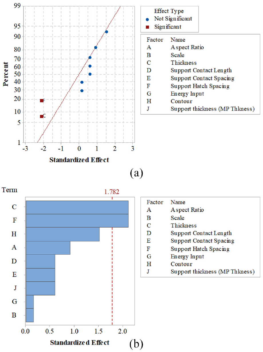
Normal probability plots (a) and Pareto chart (b) of part completion.
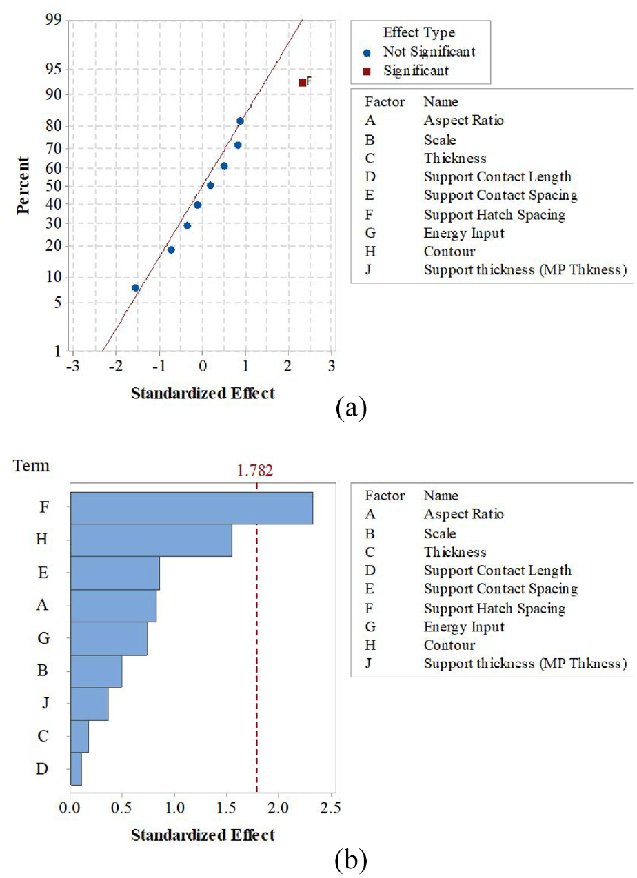
Normal probability plots (a) and Pareto chart (b) of distortion before removing.
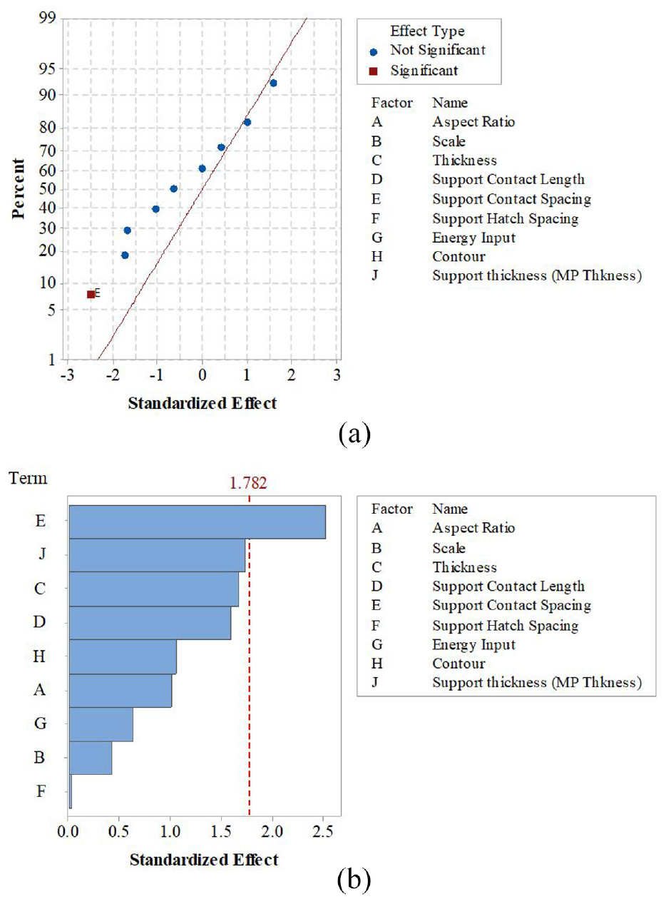
Normal probability plots (a) and Pareto chart (b) of difference in distortion/displacement.
Analyzing the first response variable recorded of part completion, parts A, B, and C were the only parts to fail, resulting in a part completion response variable of 0. In contrast, the rest parts were assigned as 1. As can be seen in Figure 5(a), both the part thickness and support hatch spacing had negative statistically significant impacts on part completion, which correlated to a higher probability that a part would fail to build ultimately. Within the factor range selected for this study, thicker parts or larger support hatch spacing gave rise to a higher possibility of failure during the building stage. By the nature of additive manufacturing, residual stress was introduced due to the high solidification rate at one layer, and more residual stresses were accumulated at this layer when melting and cooling the following stacking layers. Higher numbers of layers were suspected of bringing about more considerable residual stress on the bottom layer making it more likely to delaminate or warp, causing the failure. According to Mercelis and Kruth, 20 with the number of layers increasing, the stresses in the base plate became very large, which could induce the plastic deformation. Larger support hatch spacing provided less constraint to the built components above the support structures, which was not able to compete with significant residual stresses; hence a severe distortion could take place. The Pareto chart in Figure 5(b) revealed the equally significant standardized effects of the part thickness and support hatch spacing on the build completion. Other than those two factors, the contour supports also showed a non-negligible effect on build completion although it did not pass the reference line, which was consistent with other researchers’ work who presented the necessity of the addition of the support structures at the front of the side to avoid the deformations. 35 Other factors, including aspect ratio, support contact length, support contact spacing, support thickness, energy input, and scale with the levels selected for this study, showed insignificant effects on build completion.
The second response variable was based on the average distortion of four edges before removing from the substrate. This measurement was taken for all of the parts, even those who failed to build ultimately. The average result of the measurement with corresponding standard deviation is listed in Table 5. Figure 6(a) demonstrates that support hatch spacing had a significantly positive effect on the edge displacement, which correlated in no small warping in the direction away from the build plate. The result indicated that a larger support hatch spacing could cause more severe distortion, which confirmed with the previous claim that a larger support hatch spacing provided less constraint to the built components. It resulted in higher possibilities to cause serious distortion and warping issues away from the nominal dimension. Besides support hatch spacing, Figure 6(b) also demonstrates other relatively significant factors with the absolute values of standardized effects ranking from the largest to smallest: contour supports and support contact spacing. The effects of contour support on the residual stress were mentioned above. Support contact spacing was a factor negatively influencing the strength of the support structures, which determined the restrictions they provided against the residual stress-induced distortion and warping. No significant effects of aspect ratio, scale, energy input, scale, part thickness, and support contact length were exhibited.
The results of the measurements.
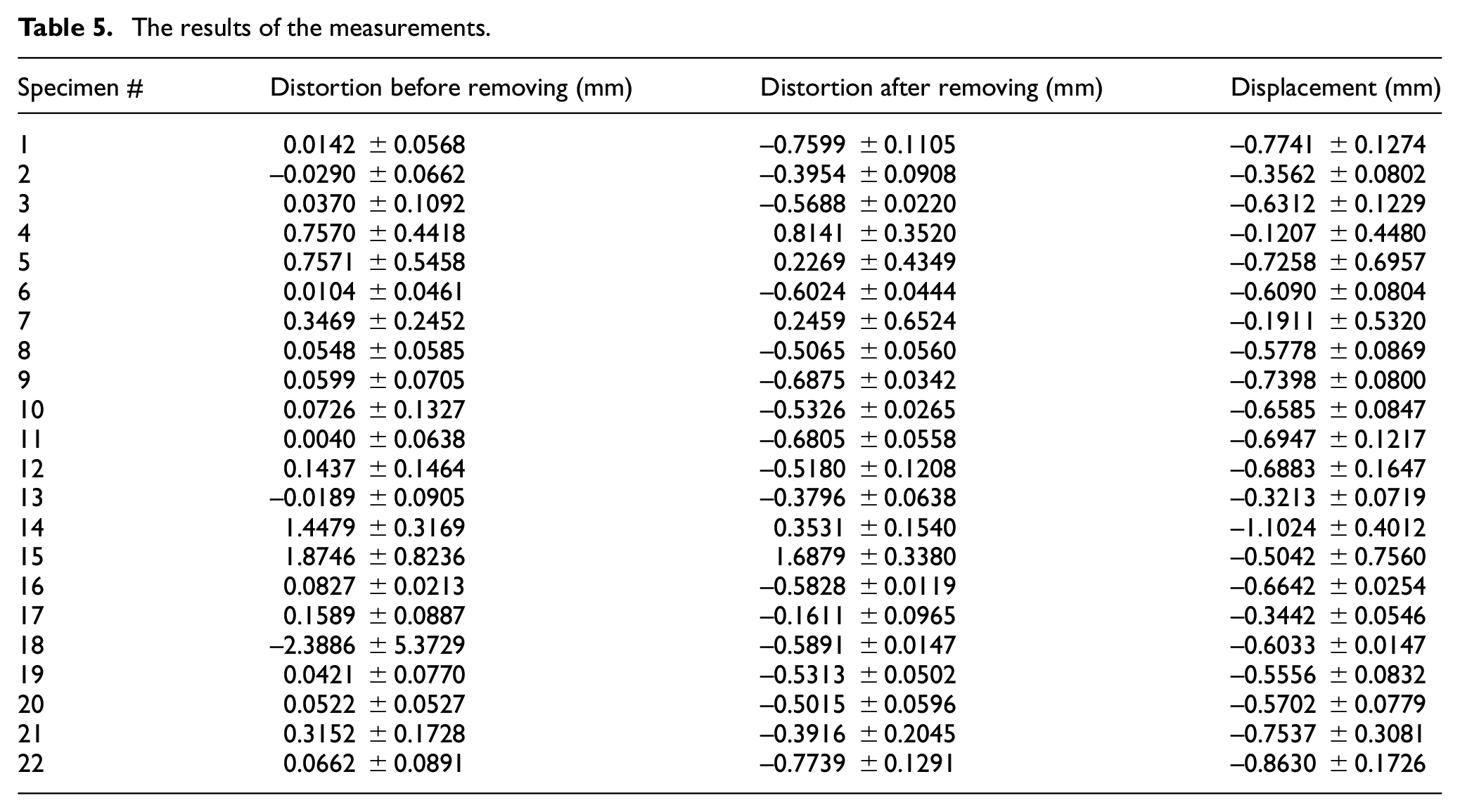
The final response variable, the difference between the parts distortion and its displacement, indirectly represented the amount of residual stress releasing during the cutting processing. Residual stress relaxes as a uniform shrinkage and a bending deformation 20 ; hence, more massive displacements suggested higher amounts of residual stress releasing. Again, these measurements and calculations were also performed for all the parts, including the three which failed. The normal probability plot in Figure 7(a) shows that support contact spacing was the most significant factor, with a negative effect. It could be inferred, that a larger support contact spacing could produce a lesser amount of the displacement, which implied fewer residual stresses could be released during the cutting processing. Block supports with smaller support contact spacing could withstand higher stresses, hence more residual stresses would be released once the support structure was removed. From the Pareto chart in Figure 7(b), support thickness, part thickness, and support contact length were identified as subdominant factors impacting the displacement. Support contact length and support thickness had a comparable but reversed effect on displacement with support contact spacing, which could affect the contact volume between parts and support structures. Part dimensions can also affect stress relaxation. According to a study presenting by Ghasri-Khouzani et al., 36 the distortion metric after detaching from the substrate was higher for disks with the smaller diameters and heights. The rest of the factors, including the contour supports, aspect ratio, energy input, scale, and support hatch spacing, demonstrated no significant impact on displacement after removing from the substrate.
It was interesting to note that results from the screening design showed the more or fewer significances of the dimensional parts and the parameters of the support structure on deformation. However, energy input seemed to be insignificant on all three responses. The selection of energy input was based on the previous work by Brown and Liou,
37
who developed the nominal process parameter (54
Conclusion
In this study, the intent was to investigate the impact of potential factors in terms of part geometry, support structure strategies, and input energy on the final build quality fabricated with the SLM process. By doing that, the identified essential factors could contribute significantly to improving the success rate of the build and final quality of the printing without the compromises of stock material and build time by the trial-and-error method. A screening build was designed to show the main effect of nine different factors, disregarding their interactions, with a minimal number of experiments. The nine factors were utilized, including three for dimensional built parts: aspect ratio, scale, and thickness; five for support parameters: support contact length, support contact spacing, support hatch spacing, contour support, and support thickness; and one more factor for energy density: energy input. A screening design was generated using Minitab 18, which allowed 22 treatment combinations in one build. During the building process, three parts failed to complete due to the extreme warping issue of the corner, which also ceased the movement of the wiper and stopped the build. Hence, the second iteration of the build was fabricated in the same build condition, excluding the parts failed or finished building. Part completion, distortion of the corners before removing from the substrate, and the difference in distortion before and after removing were measured as the three response variables used to evaluate the significance of nine factors on build completion and build-up residual stress-induced deformation and distortion. The main findings are listed as follows:
From the normal plots and Pareto chart of the various response variables, the factors with the standardized effect more than 1.782 were regarded as significant factors. In terms of the factors reflecting the effect of the build part dimension, the part thickness was identified to have a negative impact on build completion. That is, the greater the part thickness, the higher the possibility the build will fail.
In terms of support parameters, the support hatch spacing damaged the part completion, and it had a positive impact on the distortion of the corner before removing it. That is to say, the larger hatch spacing between supports could fail the build and enhance the distortion of the corner. The support contact spacing negatively affected the difference in distortion before and after removing. The other support parameters, like support contact length, support thickness, and contour support, also played subdominant roles on the final quality of the built parts. For the selected factors (e.g. support contact length, contact spacing, hatch spacing, contour support, and support thickness) in terms of support structure strategies, they were representing the support contact volume between upperparts and bottom support structures. Larger contact volume strengthened the strength of support. Therefore, support structures remained in position could stand more stresses and result in more stress-induced displacements once removed.
Little effect of the energy input can be detected on the final quality according to the three levels selected for this study,
Footnotes
Declaration of conflicting interests
The author(s) declared no potential conflicts of interest with respect to the research, authorship, and/or publication of this article.
Funding
The author(s) disclosed receipt of the following financial support for the research, authorship, and/or publication of this article: The support from Intelligent Systems Center (ISC) and Manufacturing Engineering program at Missouri S&T is appreciated. The authors would also like to acknowledge the funding and equipment through Honeywell Federal Manufacturing & Technologies under Contract No. DE-NA0002839 with the U.S. Department of Energy, and a grant from Product Innovation and Engineering, LLC.