
Abstract
Friction stir welding is recent yet spectacular process, which assumes accrescent expanse to evolve as a multi-purpose process. Its potential is greatly being tapped through large-scale experimental and computer simulation-based investigations. Several simulation and empirical models have been proposed but exact fundamental analyses on forces, material flow and strain are still absent. Complexities associated with the process are perhaps the main reason that a fundamental analysis is difficult. A comprehensive analysis of this kind is critical for understanding the evolution of microstructure, mechanical properties of joint and defect formation. This study presents an analysis of material flow, process forces and strains using first principle approach. Results have been presented as exact mathematical expressions in terms of material properties and process parameters. It was demonstrated that the material during stirring experiences direct and shear strains both when it moves from advancing side to retreating side in front of the tool and after rotation deposits behind the tool. It was also demonstrated that the strain significantly reduced from advancing to retreating side; for a typical case the shear strain greater than 10,000% prevails in advancing side and the maximum shear strain on retreating side is of the order of 6000%.
Introduction
Friction stir welding (FSW) has proved out to be a breakthrough for joining technology, being able to weld dissimilar and relatively difficult-to-weld materials effectively and efficiently. The eminent advance of FSW has attracted the interest of numerous researchers who have investigated the material flow,1–6 process forces7,8 and thermal evolution9–13 during the FSW process. These areas of investigation are largely based upon experimental methods employed to reveal the material flow behaviour; and computer-based modelling techniques used for the thermal and load analyses.
A schematic representation of FSW process has been given in Figure 1. During FSW, a rotating tool with a pin is plunged into the abutting faces of base materials, and traversed along the weld path. Heat of friction and heat due to deformation softens the material, which is under the effect of the tool rotational action known as stirring. Length of the pin is kept slightly less than the thickness of the base material. During stirring, the base material experiences very high shear and direct strain, gets rotated ahead of the tool, and while going through rotation about the pin, finally consolidates behind the tool.
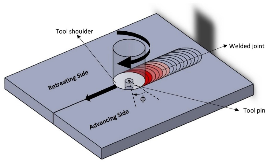
Schematic representation of FSW process.
Weld consolidation involves a great deal of both vertical (axial) force and orthogonal forces in plane parallel to plate surface (traverse and transverse forces). Process forces during FSW are, thus, usually analysed through three components, that is, longitudinal (or traverse), transverse and axial/thrust forces. Detailed thermo-mechanical models along with consistent experimental validation of axial force are available in the published literature. 14 During traversing, the tool experiences a force opposite to the traversing direction, known as longitudinal force. Broadly, the longitudinal force arises due to plastic deformation of material and friction between tool and base material as the tool traverses. The difference between resultant relative velocities of the tool on advancing side (AS) and retreating side (RS) results in a force acting perpendicular to the longitudinal force, known as transverse force. This force acts on tool in the AS of the weld. 15 Evidently, moving from AS to RS, the nature of deformation experienced by the base material varies prominently. Quintana and Silveira 16 showed that the longitudinal and transverse forces are influenced by the relationship of the tool rotational and traverse speeds.
The knowledge of process forces is critical to the design of tool and work fixture, tool’s in-process performance, defect-free joint formation and estimation of machine capacity. The real-time correlation between the occurrence of weld defects and process forces has lately been sought by Franke et al. 17 However, treatment and analysis of process forces based on exact theory of mechanics, involving material deformation, movement and its reactions is still poorly understood. The presented research work conducts a generalized yet, comprehensive analysis of transverse and longitudinal force exerted on the tool pin due to plastic deformation and flow of the base material. The two components are analysed and expressed in terms of process parameters and involved material properties.
Flow of material during welding/processing is a consequence of material deformation and movement under process forces. Thus, all the three phenomena, that is, (1) material flow, (2) material deformation and (3) process forces can be related through careful formulation under a set of assumptions devised to yield a coherent analysis of the FSW process. Given the accomplishment of FSW, such a theorized analysis of FSW carries immense value and is scarce in the available literature. The flow of material around the tool pin has been thoroughly explicated in this article for a cylindrical pin. For investigation, an element of material situated at an angle
The nature of the material flow differs in regions around the pin and just underneath the shoulder (which is also referred to as shoulder-affected region). There also exists a smaller region beneath the pin where the material dynamics are similar to those in the shoulder-affected region. However, the flow field around the pin is the most essential flow feature in FSW. 20 Moreover, in the welding of thick plates, the region affected by the lateral surface of pin is considerably larger as compared to the shoulder-affected region. The true nature of flow field in the shoulder-affected region is still unknown due to its complexity and remains the subject of further study. Analysis of region affected by pin’s lateral surface has been carried out in this study, which is then extended to the shoulder affected region. Numerical simulation concerning temperature and flow stress in the stir zone for dissimilar FSW has been recently published. 21 However, the yet unaddressed modelling of process forces for dissimilar FSW has been included and experimentally validated in the current analysis.
It should be noted that Nunes 22 devised a rather similar phenomenon to the one described here as “Wiping flow” mechanism of metal transfer and the shear surface. However, their approach is based on the plastic slip line theory whereas the analysis in this article is based on shear strain and the flow stress.
Theory and formulation
Material flow and deformation
During FSW, the material undergoes deformation ahead of the tool pin, rotates around it and finally gets deposited behind the pin. It is pertinent to mention that there is a sharp decrease in temperature at a greater radial distance from the pin surface. 23 This temperature gradient is responsible for the increase of flow stress at a greater distance from the pin. This is because, for metals, the flow stress is chiefly dependent on temperature, while the extent of the dependence on the rate of shear is less. 24 The increase of flow stress radially away from pin is significantly high, so the majority of deformation takes place in a narrow region adjacent to pin. Moreover, the sharp boundary between the heavily recrystallized and trivially deformed regions indicates that severe plastic deformation takes place in a very thin region.22,25 On one side of this region, there exists the stationary base material, and on the other side, the flowing deformed material. This region can be regarded as a shear zone in which the material undergoes severe plastic deformation.
Finite element models proved that effective strain around the weld line is asymmetric.
26
It is mentioned in Section 2.3 that at a smaller angle
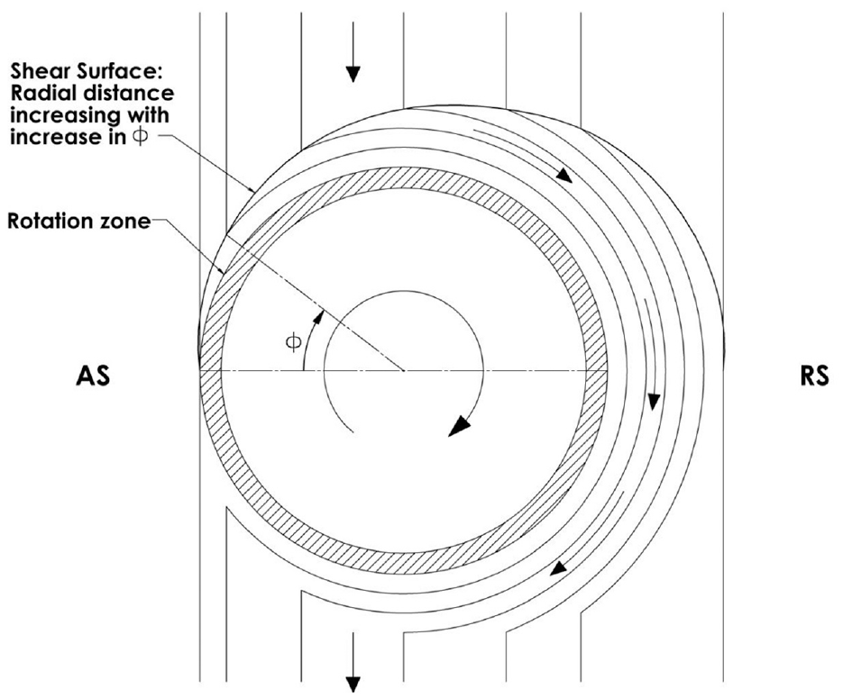
FSW flow model based on material deformation and flow.
The deformation of material is accompanied by its rotation around the pin, which begins, from the region of deformation ahead of the pin until the deposition of material behind the pin. Seidel and Reynolds
27
used a marker insert technique, to analyse material movement in the pin-affected region. They demonstrated that the markers move from advancing and retreating side and get deposited on the same side behind the tool. Furthermore, most of the material is deposited behind its original position relative to the welding direction, but none of it displaced by a distance more than one pin diameter. The computational fluid dynamics (CFD) simulation performed by Long et al.
28
suggested that the stirred material in the front of the tool gets deposited at the same position in the transverse direction. Similar findings were also reported in the investigation performed by Siedel and Reynolds.
27
As shown in Figure 2, in the present model too, the material existing at an angle
The material flow regime during FSW is characterized into different zones according to their respective flow dynamics. A rotational zone (or flow zone), existing closest to the pin, has been defined by Schmidt et al. 29 The material in this zone passes through the AS and is termed as advancing flow or counter flow. The material makes multiple rotations around the pin before getting deposited and hence, undergoes a higher shear strain. The zone between the rotational zone and shear layer boundary has been defined as transitional zone. Guerra et al. 30 also proposed the transitional zone and a nearly circular rotational zone in which the material rotates and advances with the nib. Guerra et al. proposed that the material existing in front of tool on the advancing (and some on the retreating) side enters the rotational zone. For study, the specimen was produced by simultaneously stopping the tool rotation and specimen translation. Mid-thickness horizontal (Coronal section) and transverse metallographic sections of the tool-with-pin ‘freezed’ specimen were then investigated by them. They demonstrated that fine grains produced due to severe deformation in the rotational zone appeared dark when etched. However, it seems plausible that there also exists material in the transitional zone on AS in this study. Nevertheless, since the deformation while entering the transitional zone on AS is also very severe (shown in the later section), the grain refinement becomes akin to that in the rotational zone. Consequently, materials in the transitional and rotational zones develop similar appearance and mechanical properties.
Considering such features of plastic deformation and material flow, a flow model around tool pin has been presented in Figure 2. Being very thin, the shear zone is regarded as a shear surface. Based on the presented flow model and material deformation, analysis of force and strain have been performed in the present work.
Analysis of longitudinal and transverse force applied on the tool
The material flow and plastic deformation model presented in Figure 2 and discussed in the foregoing section can form the basis for the analysis of longitudinal and transverse force applied on the tool. Additional assumptions devised for the analysis are specified below:
(1) The material around the pin undergoes motion in a ‘first in last out’ mode, as shown in Figure 2. Here, the layer which enters shear zone at the smallest value of angle
(2) The material flow is incompressible in nature.
(3) Time taken in the motion around the pin is the same for each layer. This condition has to be true for defect-free joints.
(4) First layer from the AS moves under condition of complete-stick with the outer periphery of rotational zone and there is relative sliding between subsequent layers. Since time taken by the first layer is the time taken for one revolution, time taken for all layers must be equal to the time taken for one revolution of tool.
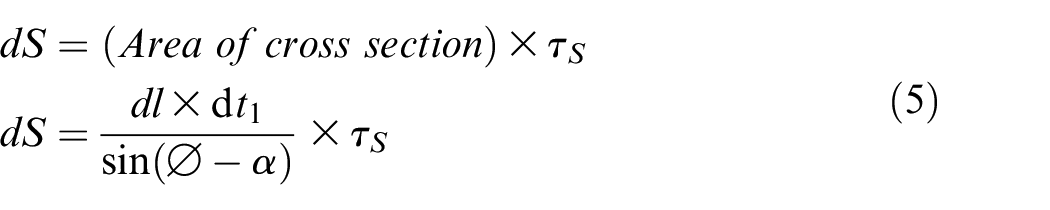
(5) The force experienced by the tool is the primary cause of material deformation at shear surface. Thus, summation of forces applied at the shear surface for each layer will give total forces on the horizontal tool cross-section.
Based on the presented model, an element at angle
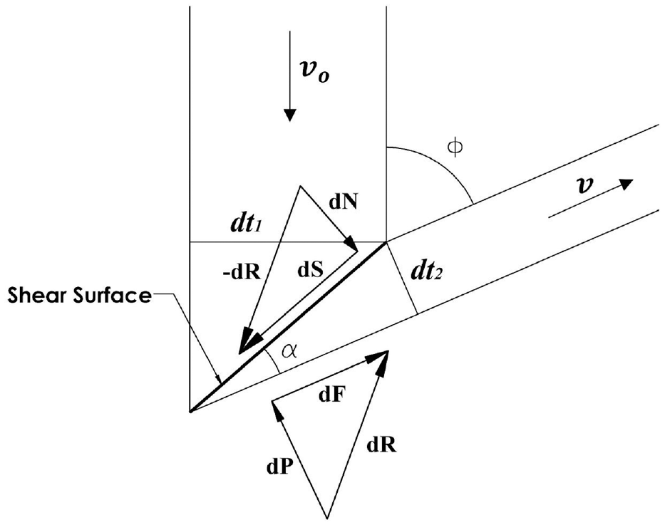
Free body diagram of one of the layers passing through shear surface.
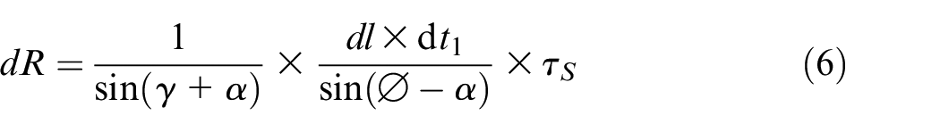
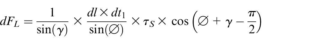
Shear force applied by the un-deformed material on deforming material at the shear surface is represented as dS. The deformed layer is considered to be in equilibrium; consequently, net force on the deformed material due to un-deformed material is equal to (–) dR. Thrust force dN, shall also act normal to dS such that the resultant to dS and dN will be equal to (–) dR.
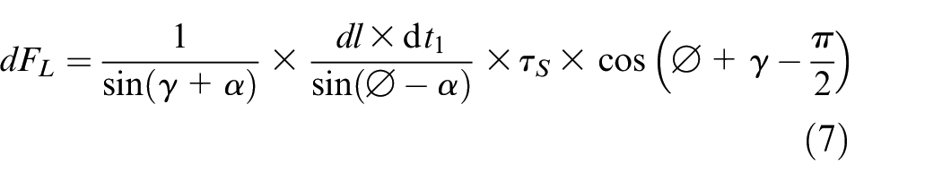
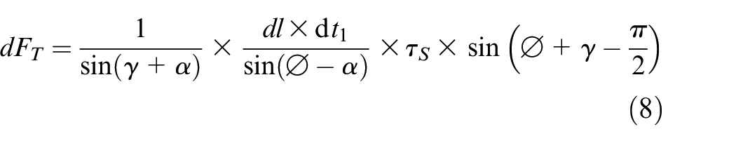
The system of forces dP, dF and dR shall be in equilibrium with the system of dS, dN and (-) dR. Accordingly, these can be represented on a circle with dR as diameter, as shown in Figure 4. Further, the system of dP, dF and dR is also in equilibrium with the net force applied on the tool. Thus, the net force acting on the pin can be resolved into two components: (1) Longitudinal force, dF
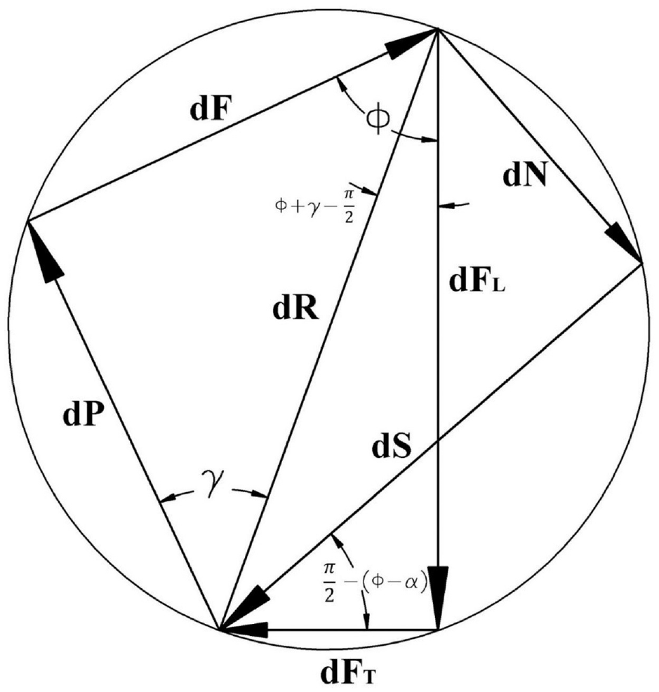
System of forces dP, dF, dR; dS, dN, -dR and dFL, dFT, -dR represented on a circle with dR as diameter.
System of forces and components of forces acting on the element so established paves the way for further analysis. Since dP is the normal force and dF is the frictional force, these forces are related as per equation (1).
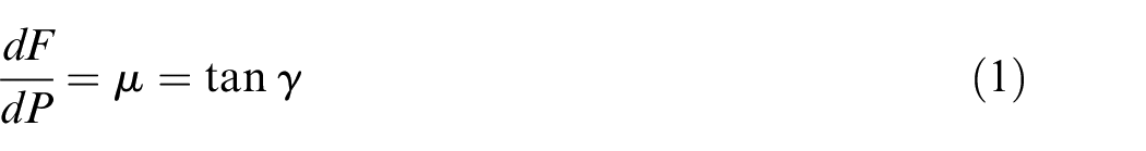
In equation (1),
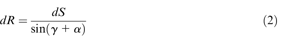
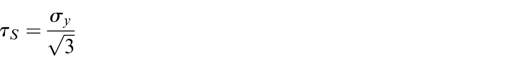
Notably, the shear force dS can be deduced as represented by equation (5).
Where,
Where
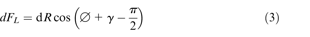
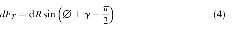
Now, for a single layer the longitudinal and transverse forces can be obtained by substituting the expression for dR into equation (3) and (4), respectively.
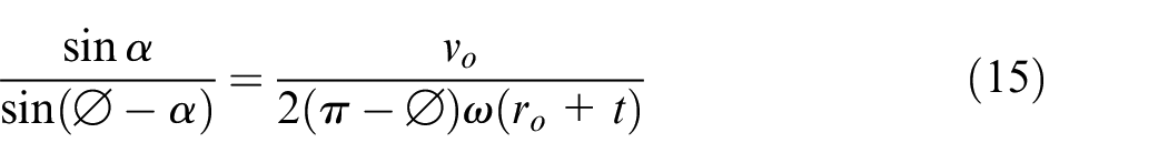
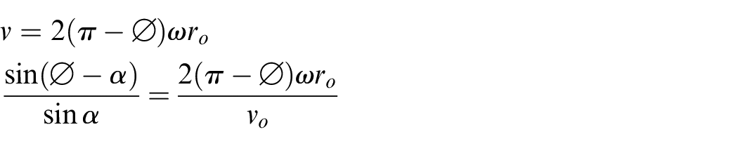
For a continuous incompressible flowing material, the law of continuity before and after deformation gives the expression as given in equation (9).
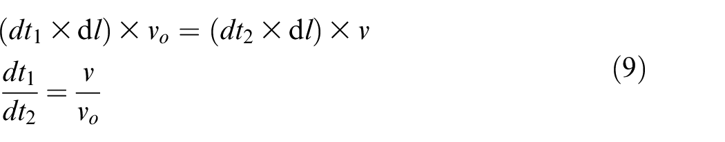
Here,

where

Substituting the above expression for v into equation (9) yields,
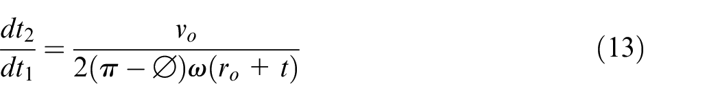
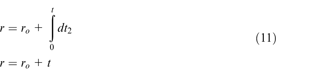
Also, from Figure 3, for infinitesimally small layer,
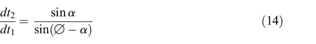
Using equations (13) and (14)
For all practical values of process parameters

Thus,

Nandan et al.
31
and Schmidt et al.
32
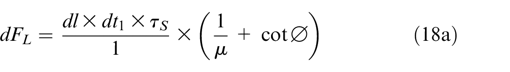
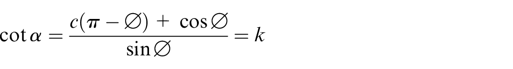
assumed sticking, sliding and partial sticking conditions at the tool/base-material interface for the thermo-mechanical computation of FSW. Based on experimental data, Schmidt et al. concluded that sticking condition exists on the tool/base-material interface. The present model addresses this matter with a slightly different approach. Assumption of the shear surface necessitates the full stick condition as the material undergoes deformation. Further, relative sliding has been assumed between subsequent layers of the deformed material. In general, for possible values of coefficient of friction for metals,

Using the above approximations, equation (7) becomes,
This, on simplification becomes,
The increase in the radial distance of shear zone with the increase in angle
Accordingly, putting
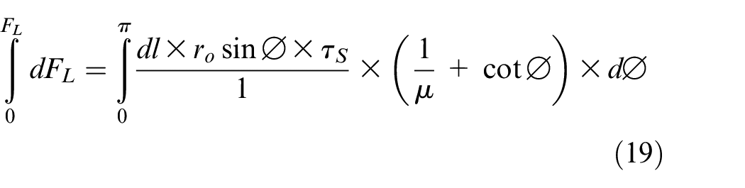
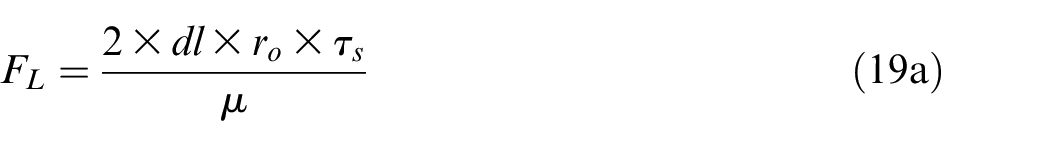
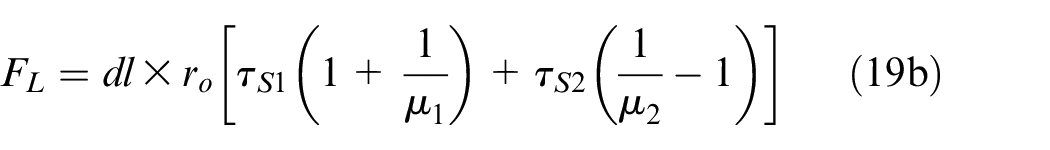
Thus, longitudinal force exerted by the weld thickness dl on the tool can be given as
For the transverse force, using approximations of (17) and (18) into (8),
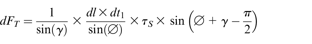
On simplification,
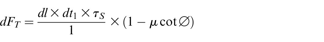
Again, using
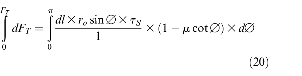
Thus, the transverse force exerted by the weld thickness dl on the tool can be given as

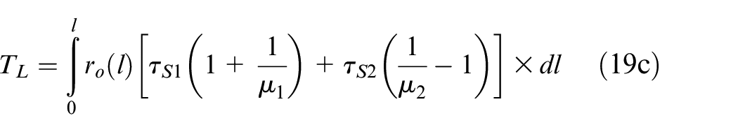
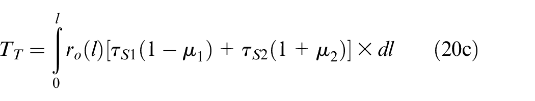
A case of dissimilar material joining
A case when dissimilar materials are joined in butt joint configuration can also be analysed, and the forces represented by equations (19) and (20) can be expressed as follows:
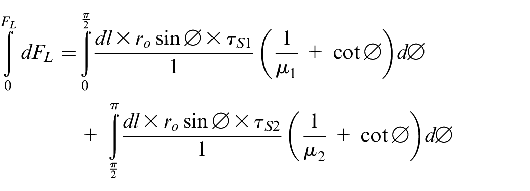
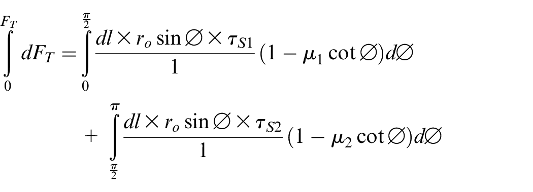
Where
Therefore, the total longitudinal and transverse forces exerted on the tool cross-section during FSW of dissimilar materials can be given as:

Likewise, although material flow dynamics in the shoulder affected region differ from that of pin affected region, the deformation of material is expected to occur in a similar manner through the shear surface. Deformation at the shear surface is assumed to be the primary cause of longitudinal and transverse forces in the present model (assumption 5). Reasonably, modified geometry of shear surface can be used to estimate total forces on the tool. It is well known that radius of recrystallized region,
Integrating equations 19b and 20b, total longitudinal force,
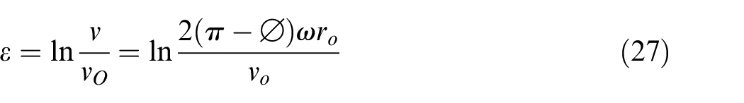
Analysis and estimation of strain experienced by the material passing the shear zone
As the base material passes through the shear zone, it undergoes both direct strain and shear strain simultaneously. Direct strain is evident from the sudden increase in magnitude of velocity of the material as expressed by equation (15), whereas shear strain is apparent by the change in the direction of velocity as the material deforms. During material flow as shown in Figure 5, the element ABCD undergoes shear deformation to form element AEFD.
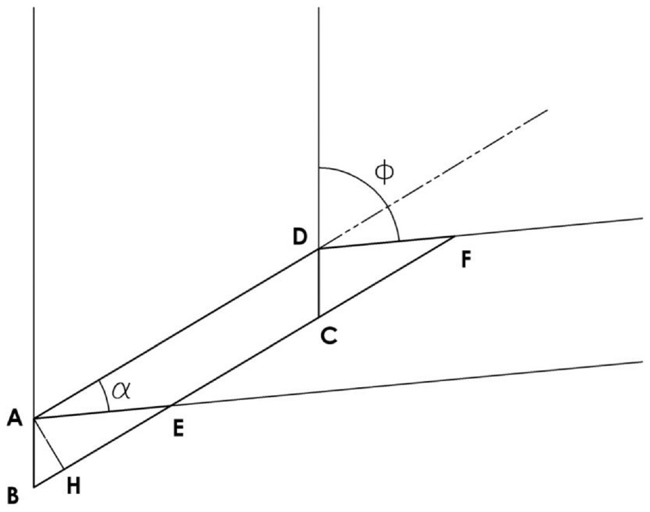
Shear deformation of one the element ABCD to AEFD on passing the shear zone.
An enlarged view of triangle ABE is shown in Figure 6. The perpendicular AH drawn on BE through point A represents thickness of the shear zone.
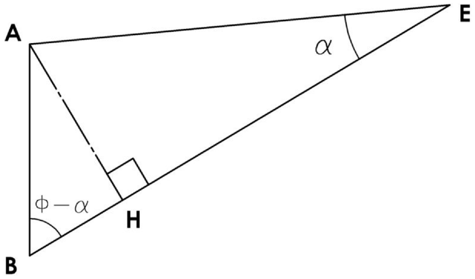
Enlarged view of triangle ABE from Figure 5.
In this situation, shear strain (
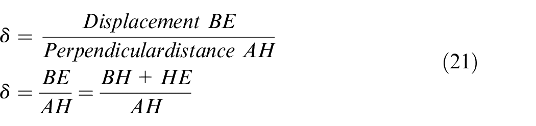
From Figure 6,
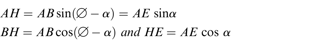
Thus, equation (21) becomes
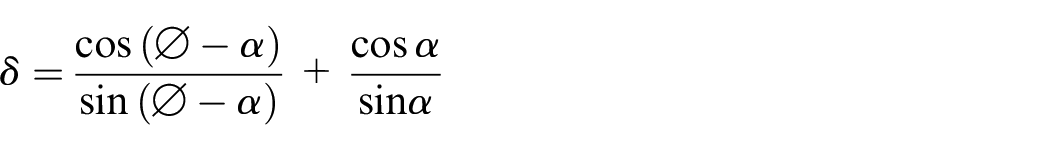
On simplification,
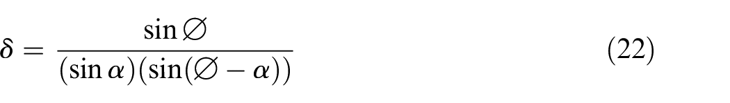
Practically, t is very small and hence can be neglected with respect to
Writing

Putting the above expression for
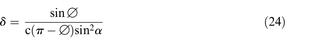
Equation (23) can be re-written as:
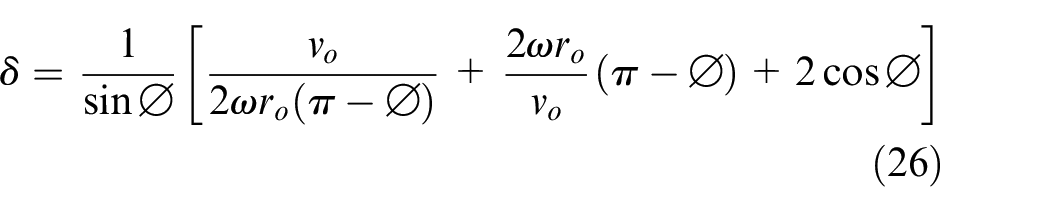
Thus,
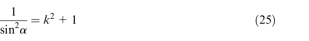
On substitution of values from equation (25) into equation (24) further simplification yields.
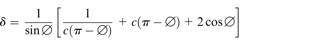
On substituting the value of c in the above expression, shear strain undergone by the base material on passing through the shear zone as a function of
Direct strain experienced by the base material can be seen as stretching of the traversing base material into the circular arc of length,
Length of base material passing through the shear zone in time taken by single revolution is equal to the Initial length LO.
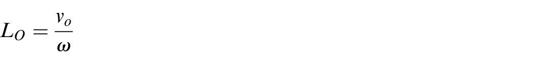
The direct true strain can thus be represented as,
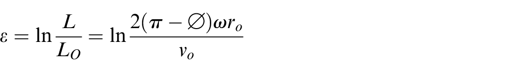
However, the direct true strain can also more simply be devised as:
To attain an estimate of strain prevailing ahead of the pin during FSW process, the values of
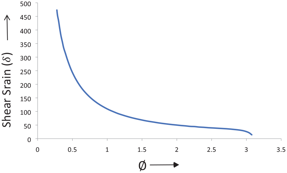
Plot of shear strain (
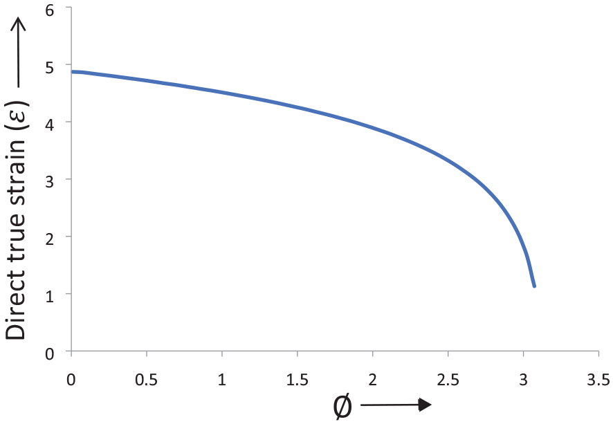
Plot of direct true strain (
Clearly, it can be seen that as
Experimental validation
The given model presents a comprehensive, yet simplistic analysis of the FSW process. The model was validated experimentally and through data from published investigations as well. The FSW experiments were performed on 2.5 mm thick plates of aluminium alloys AA7475-T761 (RS) and AA2219-O (AS) in butt-joint configuration. A sturdy vertical milling machine adapted for performing FSW and an in-house developed fixture capable to measure longitudinal force using load cell was employed. The output of load cell was recorded using custom-made data acquisition system.
34
Temperature of the weld nugget was measured using especially designed tool adaptor with customized tool-material thermocouple system.
35
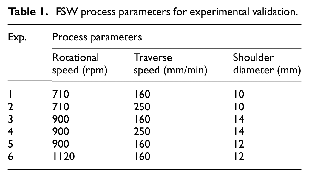
The setup used for experimentation, force and temperature measurement is presented in Figure 9. A high carbon steel tool with pin diameter of 4 mm was used for welding. In accordance with the assumptions (1) to (3) as given in Section 2.2., the experimental validation of the model could be appropriately justified only through defect free joints. Thus, for experiments, range of parameters was established through a pilot study for which defect free welds were obtained. The values of tool rotational speed, traverse speed and shoulder diameter employed for experimental validation are shown in Table 1. The macrostructural images taken from transverse sections of the welded joints, as shown in Figure 10, were used for obtaining
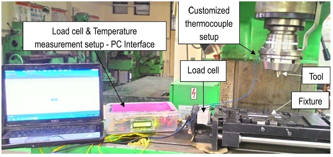
Setup for experimentation, longitudinal force measurement and temperature measurement during FSW.
FSW process parameters for experimental validation.
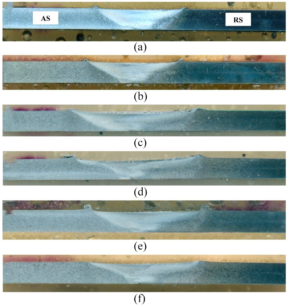
Transverse cross section of welded joints for (a) Exp. 1 (b) Exp. 2 (c) Exp. 3 (d) Exp. 4 (e) Exp. 5 (e) Exp. 6.
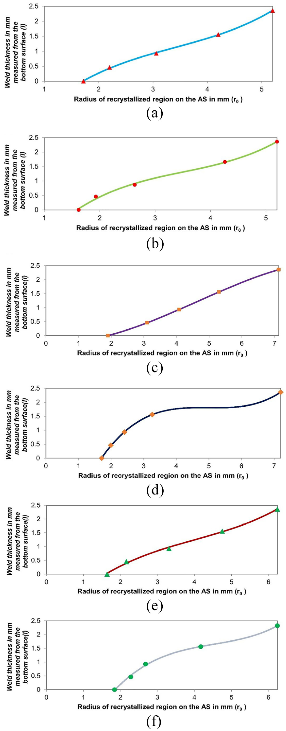
Radius of recrystallized region plotted against the weld thickness for (a) Exp. 1 (b) Exp. 2 (c) Exp. 3 (d) Exp. 4 (e) Exp. 5 (e) Exp. 6.
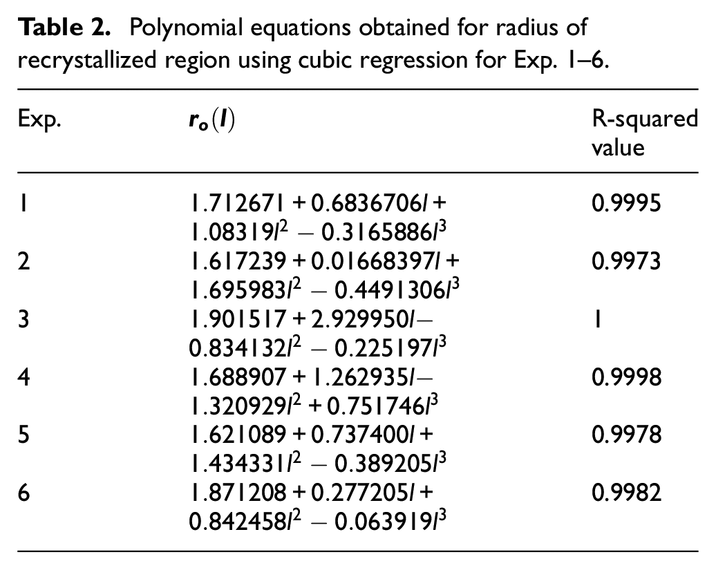
Polynomial equations obtained for radius of recrystallized region using cubic regression for Exp. 1–6.
The values of yield stress were estimated by spline interpolation of data available in the literature.
36
The strain rates were estimated via the Zener-Holloman parameter,
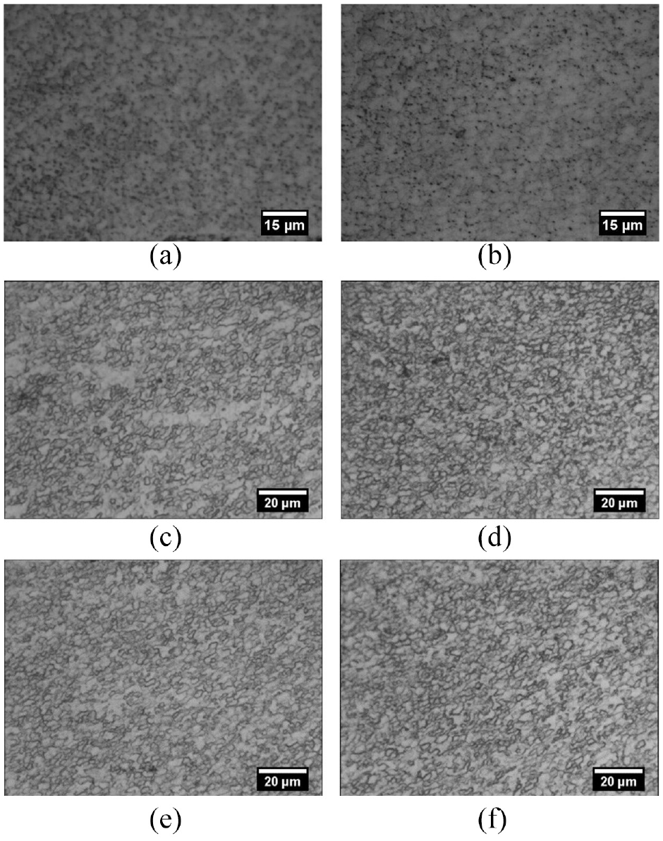
Micro-structures of welded specimen for (a) Exp. 1 (b) Exp. 2 (c) Exp. 3 (d) Exp. 4 (e) Exp. 5 (e) Exp. 6.
The following relationship between

The strain rate
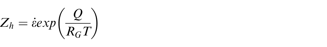
Here,
Estimated strain rates in weld nugget for Exp. 1–6.
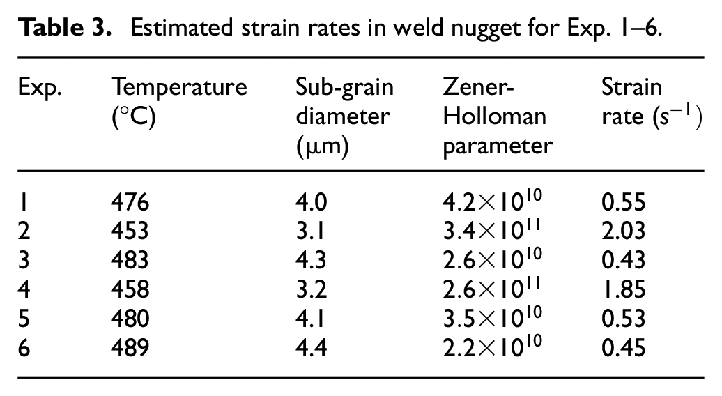
The estimated strain rate lies well within the range of strain rate observed during FSW. 5 Further, actual yield stress was calculated using the strain rate sensitivity: m, by following equation 42 :
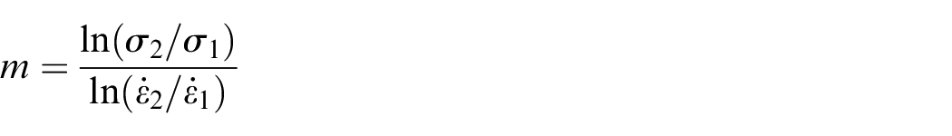
The average values of m corresponding to the measured temperatures and estimated strain rates were calculated from the works of Kaibyshev et al. 43 and Nikulin et al. 44 for AA2219 and AA7475 alloys, respectively. The total longitudinal force on the tool was calculated using the equation 19(c). Coefficient of friction value of 0.4112,31 has been used for the calculations for all the cases.
Rewriting equation (15),
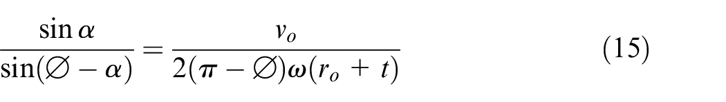
The weld macrostructures were utilised to measure the value of
From the equation (15), for values of

Whereas,

Thus,

Therefore, the approximation
Table 4 gives the estimated values of strain rate sensitivity, maximum shear yield stress, measured and calculated longitudinal force on the tool and relative error between measured and calculated longitudinal force.
Comparison of measured and calculated total longitudinal force on the tool.
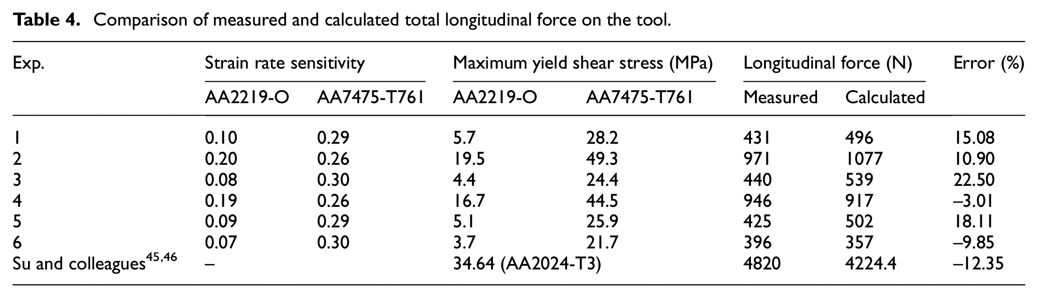
Based upon the nature of assumptions and simplicity of calculations, sound agreement is found between the measured and calculated values. For further validation, a case for similar FSW of 6 mm thick AA2024-T3 alloy at traverse speed of 160 mm/min and rotational speed of 800 rpm was considered from the works of Su and colleagues.45,46 A relative error of −12.35 % is observed in this case. The discrepancy between the experimentally measured and computed values can be attributed to the following two reasons. (a) Estimation of strain rate during FSW using Zener-Holloman parameter and sub-grain diameter can result in some degree of inaccuracy. This is because such methodology requires much more thorough statistical and micro-structural investigation of the weld structure. Also, other factors such as coarsening of grains during post weld cooling also need to be accounted to the measured sub-grain diameter. (b) Use of data interpolation and extrapolation due to limited availability of maximum shear yield stress for aluminium alloys at temperatures above 400 °C corresponding to the strain rates experienced during FSW can also incorporate some error in the calculated results. This is because of substantial dependence of longitudinal force on the maximum yield stress of the deforming materials.
Conclusion
In the present study, a basic generalized approach has been proposed for the analysis and discussion of material flow around the pin. Expressions for estimating the shear and direct strains undergone by the base material have been established from first principle approach. Further, process forces experienced by the tool pin have been computed for the welding of both similar and dissimilar materials. Valuable insight and formulation of the pin-affected region during FSW have been acquired which lead to the following deductions:
a) According to a set of sample parameters provided to the formulated expression, shear strain suffered by the material on AS lies in the order 10,000% and that on the RS lies between ∼0 to 6,618%. Direct strain undergone by the material is considerably lower than the shear strain, but is still significantly large. Direct strain greater than 421% prevails on the AS which also decreases from AS to RS. This gives a broad estimate of a range of shear and direct strains undergone by the material during FSW.
b) The computed values of longitudinal force on the tool are in good agreement with the measured values for both similar and dissimilar aluminium alloys. This proves that concept of a shear surface can be successfully applied for metal deformation in both shoulder and pin-affected regions in order to obtain the process forces during FSW.
Footnotes
Appendix
Author’s Note
When the work was carried out, Dr. A.K. Mukhopadhyay, Scientist, was with Defence Metallurgical Research Laboratory, Hyderabad. Dr. Mukhopadhyay, Research Advisor, is currently with Hindalco Innovation Center, Hindalco Industries Limited, Navi Mumbai-410208, India.
Declaration of conflicting interests
The author(s) declared no potential conflicts of interest with respect to the research, authorship, and/or publication of this article.
Funding
The author(s) received no financial support for the research, authorship, and/or publication of this article.