
Abstract
TiBw / TC4 composite material was used as the machining object of Ultrasonic vibration assisted drilling (UVAD), the single directional three-degree-of-freedom dynamical system model was established. The dynamic signal test and analysis system was used for modal experiment to identify the parameters in the model. Under the condition of dry cutting, the drilling axial force and tool vibration in the drilling process are studied. The results showed that the maximum values of the predicted and measured axial drilling force were 412.5N and 439.6N respectively, and the error rate was 6.165%, which verified the reliability of the predicted axial drilling force model. For cutting tools, the average amplitudes of simulated vibration and measured vibration were 0.1124mm and 0.1151mm respectively, with a difference of 2.402%, and the overall trends were the same, which verifies the reliability of the dynamical model. Finally, the stability of drilling process was analyzed, and the frequency and amplitude of ultrasonic vibration were analyzed. The results show that in order to expand the unconditional stability region, it is more efficient to increase the amplitude than to increase the frequency.
Keywords
Introduction
Titanium alloys and the corresponding composites are widely applied in the aerospace engineering, which originates from superior characteristics of these alloys, including high specific strength, high specific stiffness, excellent corrosion resistance, and the ability to reduce the component weight effectively.1–3 Since substantial hole making is required in the practical applications of composite components, the quality and efficiency of the hole making directly affects the performance of equipment made of these alloys, production cycle and production cost of the components. 4 Among them, TiBw/TC4 composites have higher plasticity and wide application than ordinary titanium-based composites. However, defects such as cracks, burrs, surface scratches, and tool wear are prone to occur during the hole processing, which hiders its extensive application.5,6
Ultrasonic vibration-assisted drilling (UVAD) is an efficient processing method, which has been widely studied in recent years. Moreover, beneficial process effects have been obtained in the hole-making process of difficult-to-machine composites such as titanium-based materials and nickel-based materials.7–10 Compared with conventional drilling (CD), UVAD has obvious advantages in the efficiency and precision of drilling. Yao et al. 11 conducted multiple sets of comparative tests with CFRP / titanium alloy laminated materials as drilling objects, and the results showed that compared with CD, vibration drilling can effectively reduce the average axial force, chip size and cutting temperature, and improve the quality of the hole wall. Hussein et al. 12 took fiber-reinforced materials as the research objects, and added low-frequency and high-amplitude vibrations to the feed direction of high-speed steel drills. Their study showed that compared with CD, vibration drilling not only effectively suppresses the occurrence of burrs at the exit, but also significantly improves the quality of the hole wall. Then they proposed that appropriate vibration parameters can effectively improve drilling performance, thereby increasing the processing efficiency and quality of the reinforced matrix composites. Furthermore, UVAD has the characteristics of intermittent cutting, which can effectively reduce the drilling force, drilling heat and tool wear. Therefore, the tool life and the processing efficiency are improved.13–16 However, most researches concentrate on the experimental analysis of UVAD, while few of them focus on its universal mechanism.
In order to predict the effect of the ultrasonic vibration on the drilling process, some scholars have focused on the creation of vibration drilling models. Pavlovskaia et al. 17 established a three-mass vibration drilling model, which is consisted of the spindle & spring-damping & tool model and table & spring-damping & ground model. And they found it has more realistic simulation results compared with two-degree-of-freedom models. However, the model simply divided the drilling system into three parts, and the connecting parts are connected by spring and damping, without considering the coupling state of the tool and the workpiece. Yuan et al. 18 established a cutting force model of carbon fiber reinforced composite T700 by brittle fracture method. But when analyzing the correlation between the cutting force and cutting amount, cutting speed and feed rate, the results of the drilling experiments were simply summarized, and no exact correlation was established. It is observed that the dynamical properties of UVAD has not been fully revealed, and its theoretical basis is not mature.
It should be indicated that the cutting stability region is an important index to measure the processing stability of the cutting system. At present, the research on cutting stability has a comprehensive theoretical basis in milling, 19 but the research on drilling stability is very few. In order to analyze the flutter generation principle of the rotary ultrasonic drilling of a robotic arm, Dong et al. 20 proposed a stability calculation model for vibration drilling and obtained a stability lobe of the Al7075-T7 material. However, they directly adopted the cutting force coefficient of the milling processing of Al6082 by Faassen et al. 21 Since they ignored the material characteristics and processing methods, the reliability of the results needs to be further studied. Therefore, the stability analysis of UVAD system was performed in the present study. Moreover, the cutting force coefficient was calculated by orthogonal method, and the stable lobes were drawn. Furthermore, the correlation between the stability region with the amplitude and frequency of ultrasonic vibration was investigated.
In summary, UVAD is an effective method for obtaining high-quality holes in difficult-to-machine composites. However, since the existing dynamical models of the ultrasonic vibration drilling are not complete, and most of them are simple analysis of drilling force and other single factors, it is not possible to further study the processing effects of UVAD. Based on existing researches, we simplified the process of vibration drilling into the series dynamical problem of rigid body and spring damping system. Combined with the CD theory, a single directional three-degree-of-freedom drilling dynamical model was established, and the feasibility of the theoretical model of drilling dynamics was verified by experiments, which provided a useful reference for the UVAD processing of difficult-to-machine composite.
Establishment of drilling processing dynamical model of UVAD
Material properties of TiBw/TC4 composite
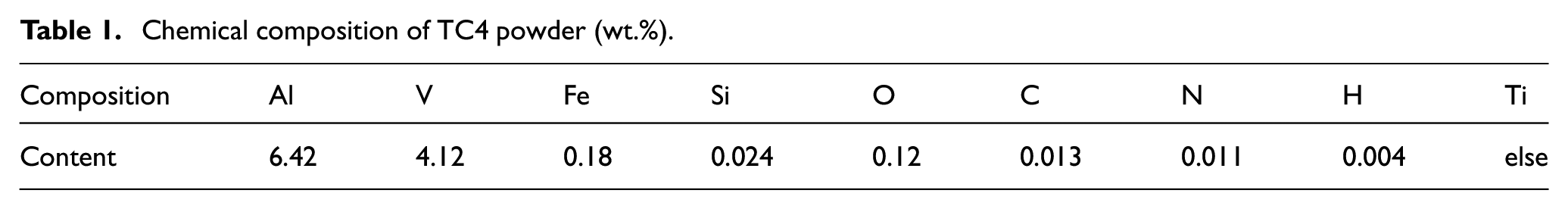
In this paper, TiBw/TC4 composite with a volume fraction of 8.5% was used as the drilling object. TC4 and TiB2 powders were mixed at a certain ratio and TiBw/TC4 composites were prepared by high temperature hot pressing sintering. 22 The detailed chemical components of TC4 are listed in Table.1. Tensile testing of the prepared TiBw/TC4 composite, as well as the TC4 alloy alone, was performed and the stress–strain curves are shown in Figure 1. The yield strength of pure TC4 alloy is 855 MPa. After the addition of the 8.5 vol.% reinforcement phase, the resulting TiBw/TC4 has a yield strength of 1288 MPa representing a 51% enhancement compared to pure TC4. Thus, adding the reinforcement phase can markedly enhance the strength of TiBw/TC4 composites; however, this also leads to increased difficulties in secondary processing. 23
Chemical composition of TC4 powder (wt.%).
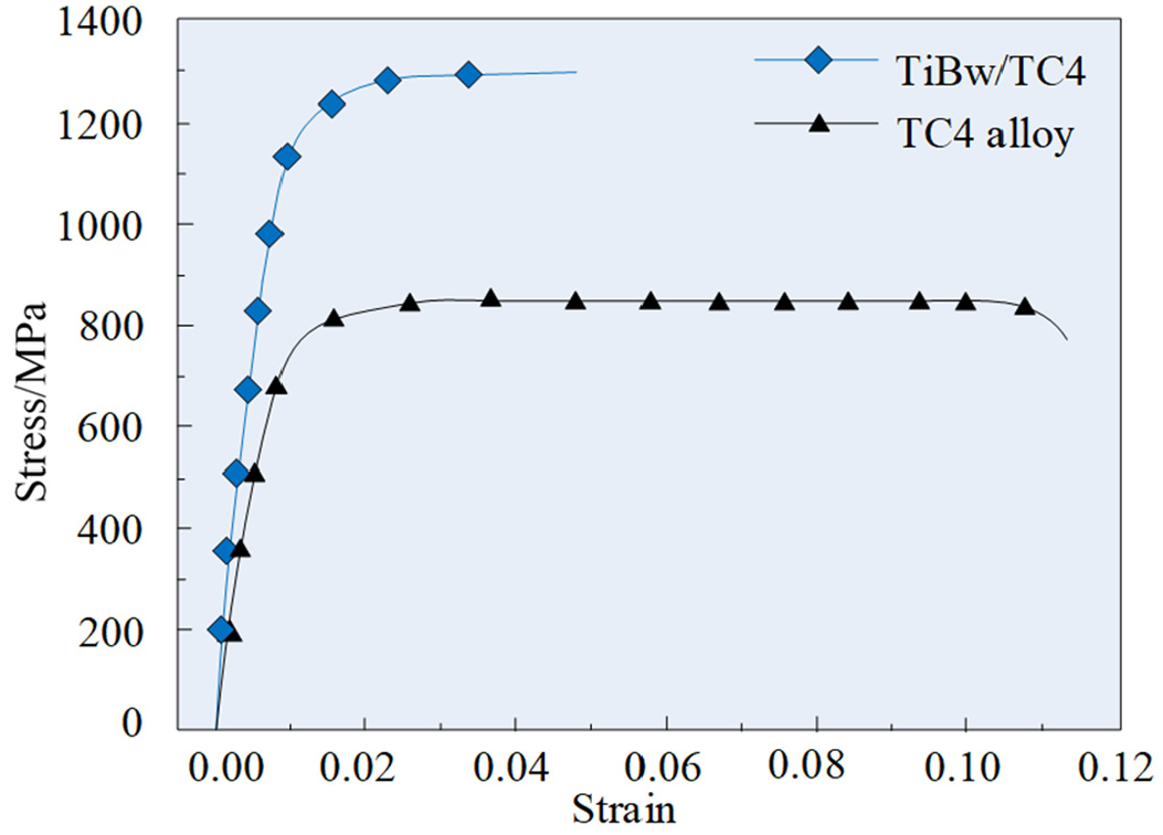
Tensile stress–strain curve of TiBw/TC4 and pure TC4.
The drilling principle of UVAD
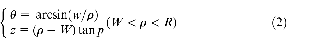
Compared with CD, UVAD superimposes an axial ultrasonic vibration on the basis of rotary motion and feed motion. In order to facilitate the analysis of the trajectory of the drilling process, Figure 2 shows the polar coordinate system established with the twist drill core as the origin. It should be indicated that p is half front angle, W is half blade length, w is half core thickness, and R is twist drill radius.
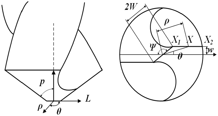
Polar coordinate system of twist drill.
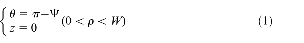
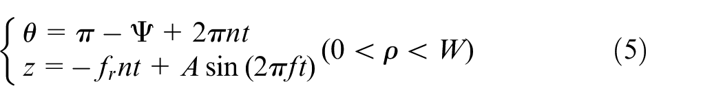
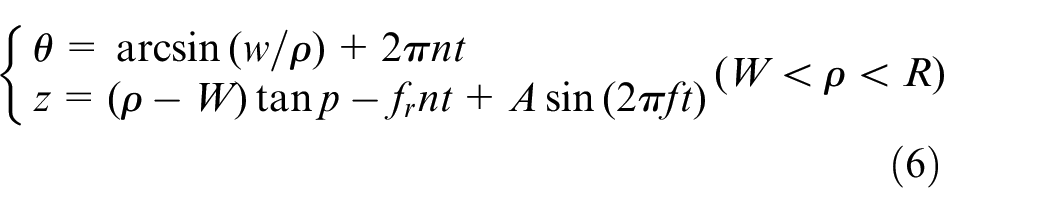
The cutting edges of a twist drill include chisel edge and main cutting edge. When analyzing the movement of any point on the cutting edge of twist drill, it needs to be divided into two parts. ρ is the polar diameter of the X point in this polar coordinate system, and the coordinates on the chisel edge (0 < ρ < W) and the main cutting edge (W < ρ <R) at time can be expressed as:
In a CD process, the motion equation of the drill bit is:
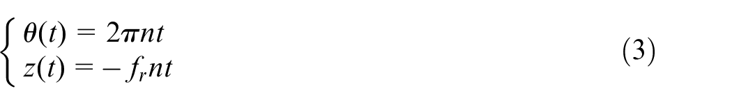
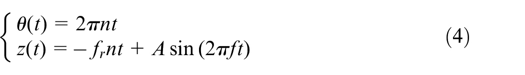
where θ, z, n, fr, and t represent the drill angle, axial coordinates, spindle speed, feed per revolution, and drilling time, respectively. Figure 3 shows the principle of the UVAD processing, and Fz and M represent the axial force and torque of drilling force respectively. Since there is an ultrasonic vibration in the axial direction, the equation of the motion of the drill can be expressed as:
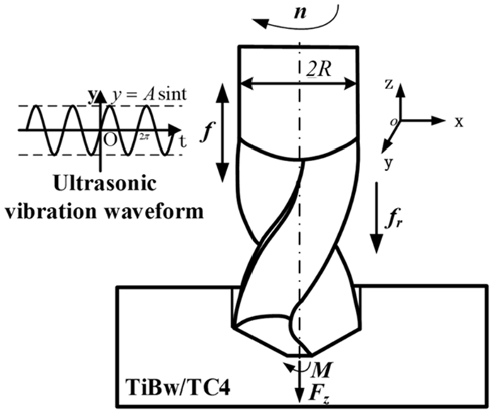
Principle of UVAD.
where A and f denote the amplitude of the ultrasonic vibration and the frequency of the ultrasonic vibration, respectively.
After taking the initial position coordinates of equations (1) and (2) into equation (4), the trajectory of any point on the cutting edge of the axial ultrasonic vibration drilling can be obtained:
The two points on the main cutting edges that are equidistant from the drill core are analyzed by equation (6). Figure 4 shows the drilling trajectory of a twist drill under the working condition of n = 25 rev/s, fr = 0.04 mm/rev, f = 35 kHz, A = 2.5 μm, W = 0.6 mm, and p = 70°.
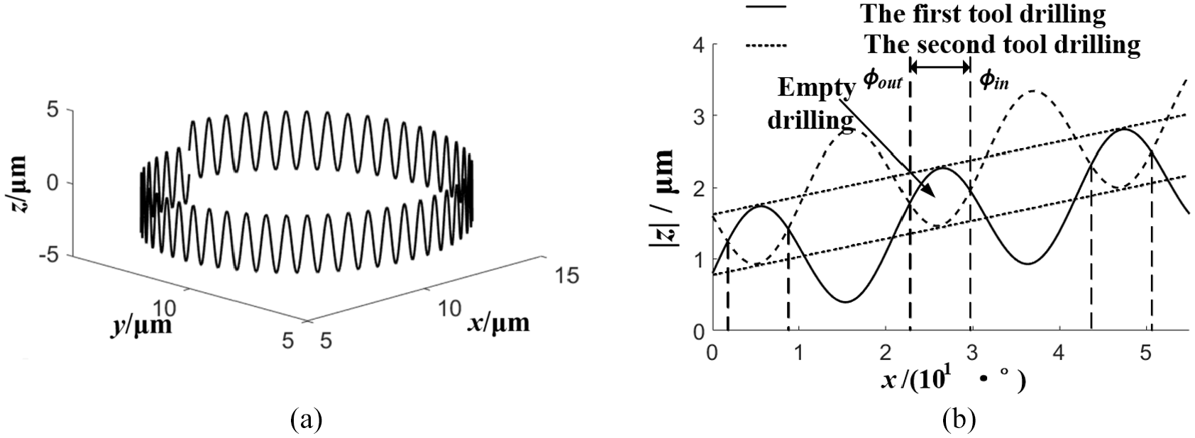
Drilling trajectory: (a) drilling trajectory of a point on the tool and (b) trajectory expansion of UVAD.
Figure 4(a) shows that the trajectory of the tool presents a wave-spiral rise. Figure 4(b) shows that the adjacent position of two cutting edges with phase difference π, when the position of the second cutting edges is higher than the position of the first cutting edges, an empty drilling region is formed. Moreover, equation (4) indicates that in the premise of an empty drill, the ultrasonic vibration amplitude (A) is greater than the axial feed amount per revolution (fr).
Prediction model of the axial drilling force
In the drilling process, the drilling force is mainly an axial force with a small torque. In the analysis, the effect of the torque is ignored and only single directional dynamical properties on the feed direction of drilling are studied. In this section, a prediction model of the axial force for vibration drilling is established based on the vibration cutting theory and the shear zone model of metal cutting proposed by Oxley. 24 Due to the symmetry of twist drills, only one of the two main cutting edges is analyzed. Length differential unit (dl), which is between the intersection of the cutting edge and the transverse edge with the points on main cutting edge whose distance from the axis is radius rand the differential unit of the shear force (dFs) generated by dl are:
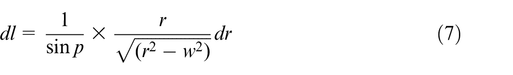
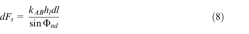
where kAB is the shear flow stress on the shear plane. Moreover, hl and Φnd show the dynamic cutting thickness perpendicular to the work cutting plane and the dynamic shear angle (rad), respectively.
Equation (9) shows that the axial force differential (dFl) of any selected differential unit dl on the main cutting edge can be obtained from the study of Oxley. 24
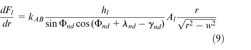
where,
where, d’=2W stands for the diameter of the chisel edge. Equation (10) indicates that the vibration cutting force of the main cutting edge can be obtained by integrating the expression of dFl according to boundary conditions determined based on the geometric parameters of the main cutting edge and chisel edge of the drill.
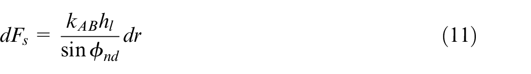
Equation (11) describes the differential expression of the shearing force for differential unit length of chisel edge (dr) according to the orthogonal cutting model of Oxley.
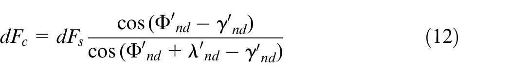
Equarion (12) shows the differential expressions of the generated axial force and torque for any point on the chisel edge whose distance from the bit axis is r (the radius).
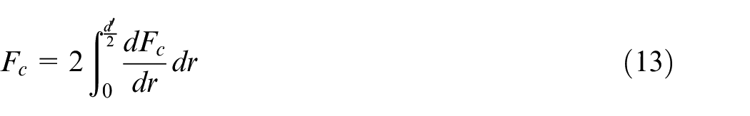
Equation (13) shows that the axial cutting force of the chisel edge can be obtained by integrating the entire length of the chisel edge.
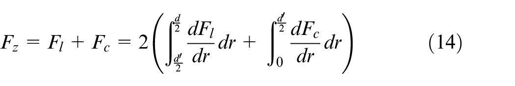
Equation (14) described the expression of the total axial force on the tool during the UVAD processing.
Establishment of single directional three-degree-of-freedom dynamical model
The differential equation for the dynamics of vibration drilling is described as the following:

where, [M], [C], [K], {x (t)}, and {f (t)} are the mass matrix, the damping coefficient matrix, the elastic coefficient matrix, the location vector, and the force vector, respectively.
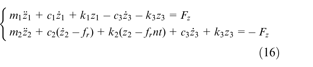
During the drilling process, the tool and the workpiece are highly coupled, and the force state is extremely complicated. Therefore, the coupling correlation between the tool and the workpiece should be initially investigated. The coupling process between the tool and workpiece can be approximated as the bending deformation of the fiber in the cutting layer under the extrusion of the chisel edge. Figure 5 shows that if this deformation process is equivalent to a spring damping system, a single directional three-degree-of-freedom dynamical model of ultrasonic vibration drilling with basic motion can be obtained. Therefore, a Cartesian coordinate system is established according to the right-hand rule. The displacement parameters of workpiece and tool are expressed in the free coordinate system (oz), which are recorded as z1 and z2, respectively. There are spring damping systems between workpiece and table, and between tool and spindle. k1 and c1 are the elastic coefficient and damping coefficient of the table, respectively. Moreover, k2 and c2 are the elastic coefficient and damping coefficient of feed spindle and tool holder in series, respectively. k3 and c3 are the equivalent elastic coefficient and the damping coefficient of drill and workpiece in series. The added degree of freedom z3 is the deformation of the equivalent system. Equation (16) shows the dynamical equation under this model, where Fz is the axial force. It should be indicated that the elastic characteristics of each part of the model are characterized by a spring damping system.
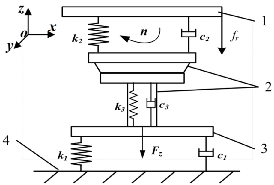
Single directional three-degree-of-freedom dynamical drilling model.
Identification of modal parameters
The series expression of the acceleration frequency response matrix of the multi-degree-of-freedom vibration is described as:
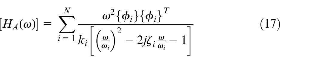
In equation (17), [HA(ω)] is the acceleration frequency response function matrix of the structure. ϕi, ki, ωi and
The dynamic analysis theory indicates that the coupled equations can always be decoupled under certain conditions to obtain several unrelated single-degree-of-freedom equations. 25 The test instrument and software are utilized to obtain natural frequency, modal shape and damping ratio of each order directly. After ignoring the influence between adjacent modes, equation (17) is approximately rewritten as:
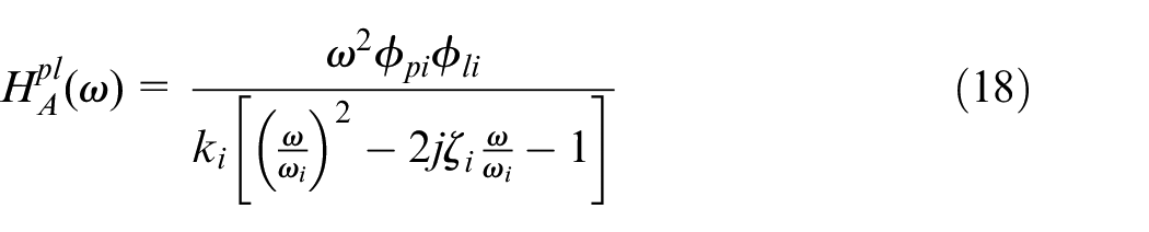
Since equation (18) is completely consistent with the form of the single-degree-of-freedom frequency response function, the single-degree-of-freedom method can be used to identify the modal parameters of the system order by order. Moreover, equation (18) is rewritten in a complex exponential form as follows:
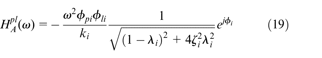
In equation (19),
Dynamic analysis
In summary, a single directional three-degree-of-freedom dynamic model is established in the present study. Figure 6 shows the flow chart of the specific model establishment and verification analysis.
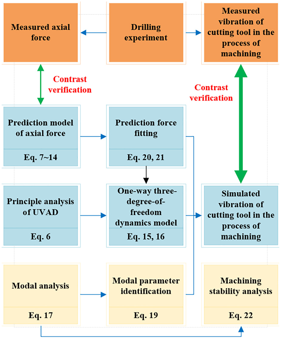
Model establishment and verification analysis.
The establishment and analysis of the experiment
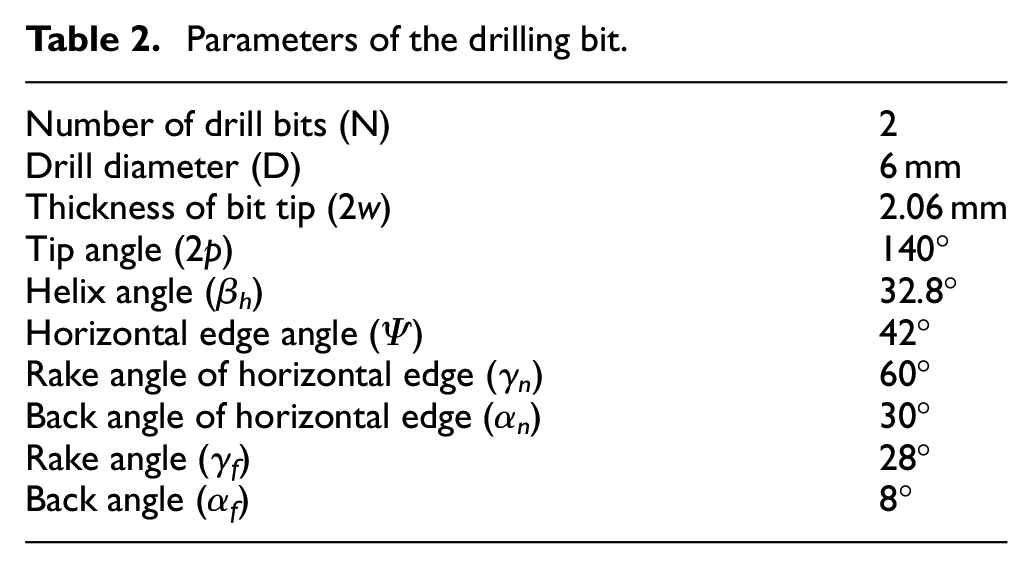
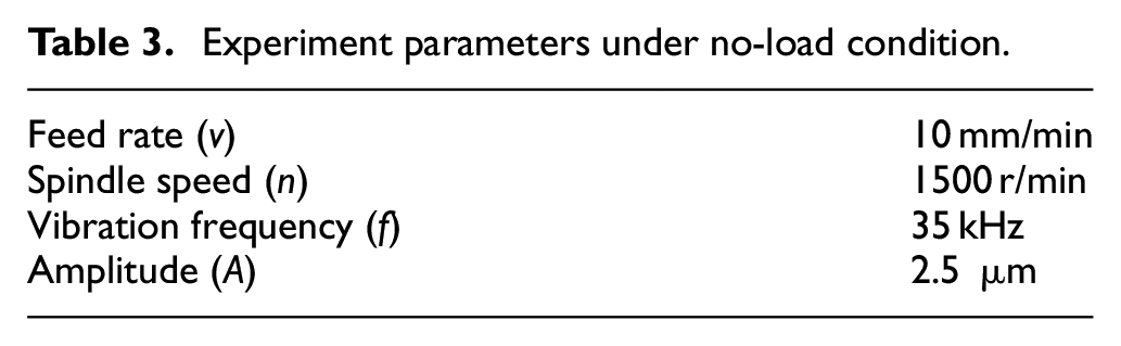
The experiment includes two parts: UVAD and modal parameter identification. Moreover, the experiment object is a VMC-C3OH five-axis machining center. Figure 7 shows the experiment site and main equipments. Table 2 presents the parameters of the drilling bit, and the experiment parameters of drilling are shown in Table 3.
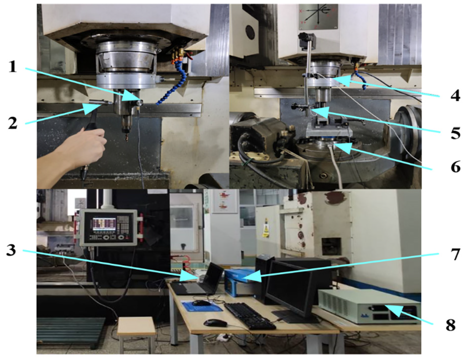
Experiment site and main equipments.
Parameters of the drilling bit.
Experiment parameters under no-load condition.
The modal parameters provide the basis for the vibration characteristics analysis, the diagnosis and prediction of vibration faults and the optimization design of structural dynamic characteristics. 26 Accurate modal parameters are necessary to establish the dynamic model of UVAD. In this paper, the modal parameter of the drilling system are determined by the experimental modal analysis method, which provides necessary data for the derivation of the dynamical equations.
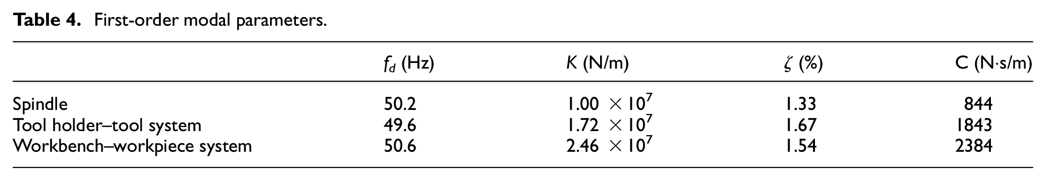
The single-point vibratory hammer method is used in the VMC-C3OH five-axis machining center. The main instruments in this experiment include a DH5922D dynamic signal test-analysis system (including 4-channel acquisition card), a LC02 hammer and an IEPE three-way acceleration sensor. The measurement is divided into three parts: the spindle, the tool holder (including the tool) and the table. The three-way acceleration sensor is initially fixed at a suitable position on the spindle through a magnetic seat, and then multiple positions are selected to perform the force hammer excitation multiple times. The force hammer excitation signal and output signal of the acceleration sensor are transmitted to the data acquisition system, and then the frequency response function (FRF) of the spindle is obtained by analysis and calculation. Moreover, the modal test of the tool holder (including the tool) and table is performed by the same method. The modal test site is shown in Figure 7. The modal test is carried out on the UVAD system and PolyLSCF method is used for the curve fitting. Figure 8 shows the measured and fitted curves of the frequency response. Moreover, Table 4 shows the identified first-order modal parameters, and the calculated parameters of the equivalent spring damping system are shown in Table 5.
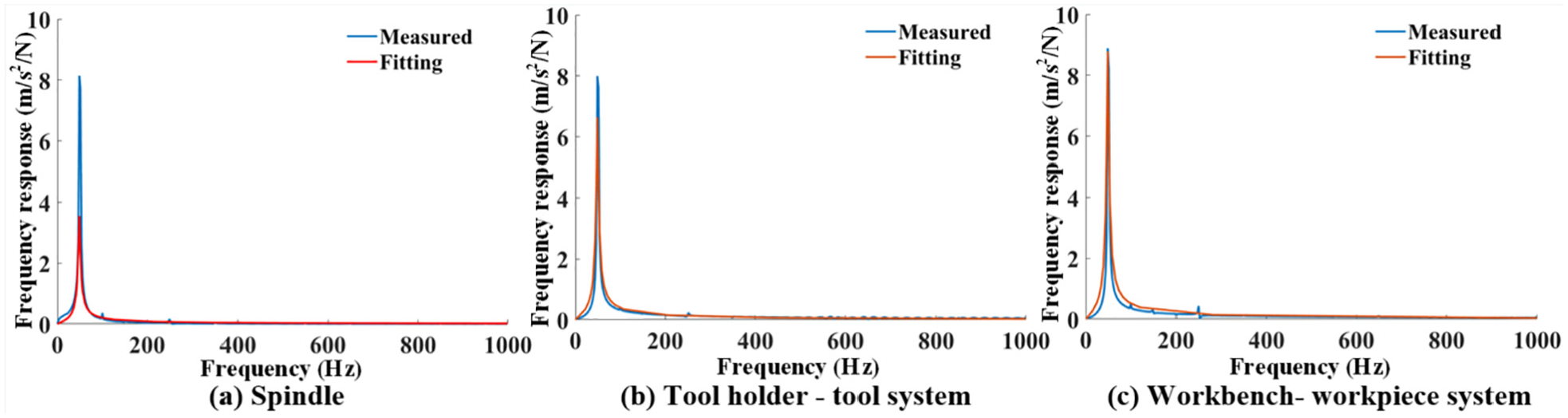
Measured and fitted curves of the frequency response.
First-order modal parameters.
Parameters of the equivalent spring damping system.
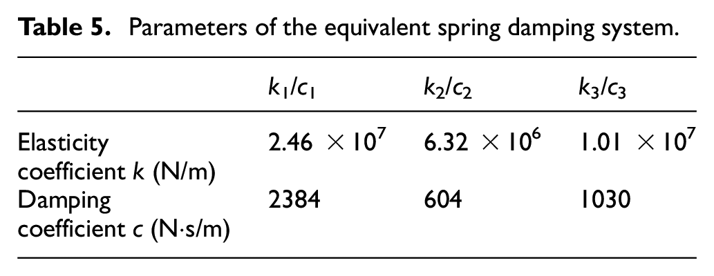
Figure 8 and Table 4 show that the three parts of the system has similar first-order dominant frequency of about 50 Hz. However, there is a large difference in the frequency response at the dominant frequency. The minimum frequency response of the spindle and the maximum frequency response of the workbench-workpiece system are about 3.6 and 9.0 m/s 2 /N, respectively. The main axis has the smallest modal stiffness and damping coefficients, and the workbench-workpiece system has the largest corresponding values. Table 5 shows that the spring damping system between the workpiece and workbench has the highest elastic coefficient and damping coefficient. Moreover, the spring damping system between the tool and spindle has the lowest corresponding values.
Model simulation and verification
The predicted curve of the drilling force is drawn according to equations (8) to (14) and the comprehensive softening coefficient (g) proposed by Feng et al. 27 Figure 9 illustrates the predicted and measured results of the axial force. The obtained results show that the largest predicted axial force and the largest measured axial force are 412.5N and 439.6N, respectively. Moreover, the error rate is 6.165%, and the predicted and measured fluctuation frequencies are both 25Hz, which verifies the reliability of the prediction model of axial force. The mean value Y and the amplitude G of the axial drilling force of the prediction model are fitted by the least square method. Moreover, the objective function is Fz = Y + Gsin (50πt). The fitting method is performed as the following: the curve is divided into three stages of drilling in, stable drilling and drilling out. The average value curve of the axial force is obtained by the polynomial fitting. Finally, a sine-like wave with the corresponding amplitude and frequency curve is obtained. Equations (20) and (21) denote the fitting results.
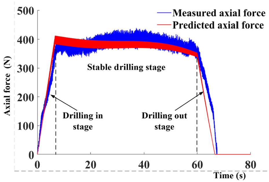
Axial force.
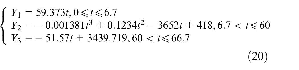
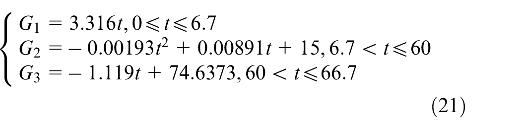
Figure 10 shows the comparison of measured and simulated vibration during drilling. In the process of stable drilling, the average values of the measured and fitted amplitudes are 0.1124mm and 0.1151mm respectively, with a difference of 2.402%. The reliability of the single directional three-degree-of-freedom model is verified. In addition, it is also observed that the amplitude and axial force of the fitted tool are highly consistent, which indicates that there is a direct correlation between the axial force and drilling vibration. There is a large error of comparative test in the stages of drilling in and drilling out. Moreover, the amplitude fluctuation in stable drilling stage is small. The main sources of the error are as follows:
(1) Fitting error of the axial drilling force. This error is equivalent to the error between the measured and fitted axial forces.
(2) Self-excited vibration during the drilling. Since the eddy current displacement sensor is installed on the machine tool through a bracket and the bracket is long, the self-excited vibration is amplified after the transmitted through the long bracket.
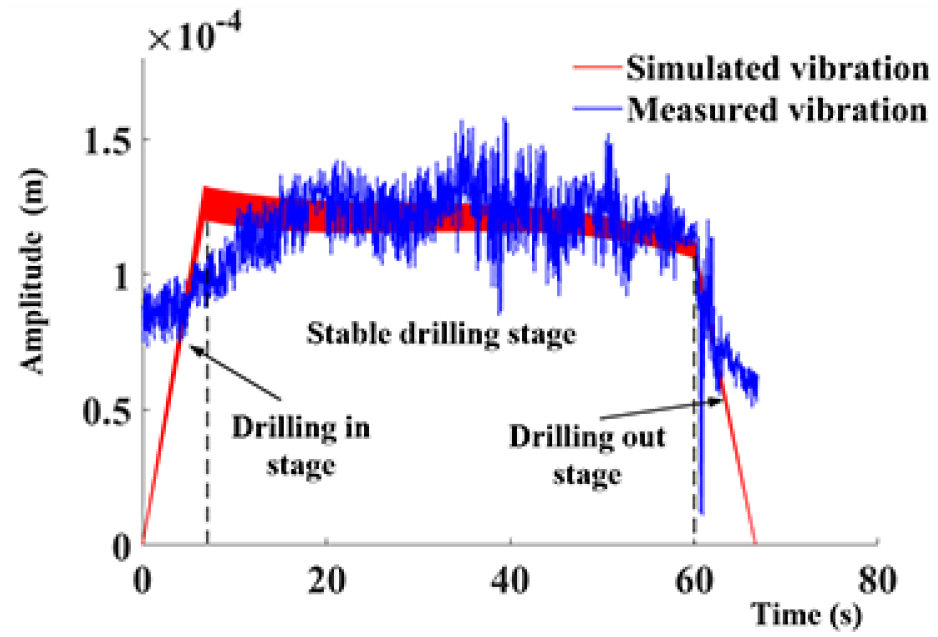
Measured vibration and simulated vibration of the tool.
The results show that the measurement error caused by the self-excited vibration has obvious impact on drilling in and drilling out stages. Moreover, it is observed that the influence of the axial force fitting error is mainly reflected in the stage of the stable drilling.
Stability analysis and stability lobes
A two-dimensional correlation between the critical transverse cutting width and the spindle speed is established through the stability lobe of the drilling stability region, which is an important reference for stable drilling and avoiding chatter effectively. Dong et al. 20 derived the abovementioned correlation as:
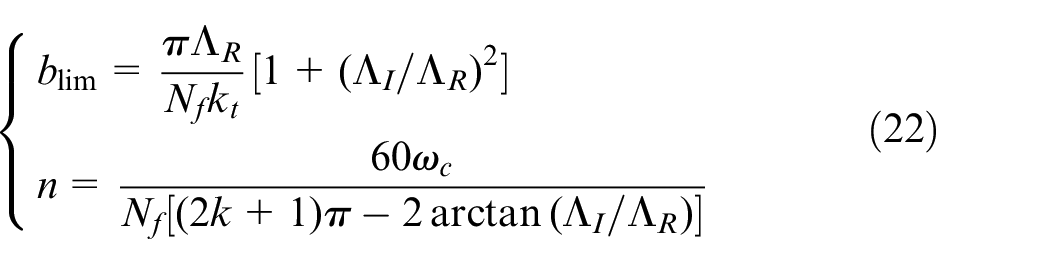
where blim is the critical cutting width, n is the spindle speed, kt is the normal drilling force coefficient, Nf is the number of cutting edges, k is the number of leaflets, ωc is the frequency, ΛR and ΛI are the real and imaginary parts of the root of the system characteristic equation, respectively. Referring to the calculation method of force coefficient of Stepan28,29 and combining with the method of milling stability lobes, the stability region of UVAD is analyzed. The drilling force coefficient equation is as follow:
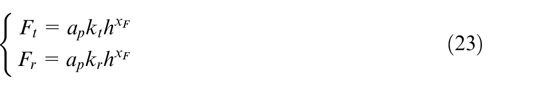
where Ft is the normal drilling force, Fr is the tangential drilling force, kr is the tangential drilling force coefficient, ap is the cutting width, h is the thickness of chip and xF = 0.744 is the correction coefficient, 21 respectively. Besides, the drilling force coefficients are shown in Table 6.
Drilling force coefficients.
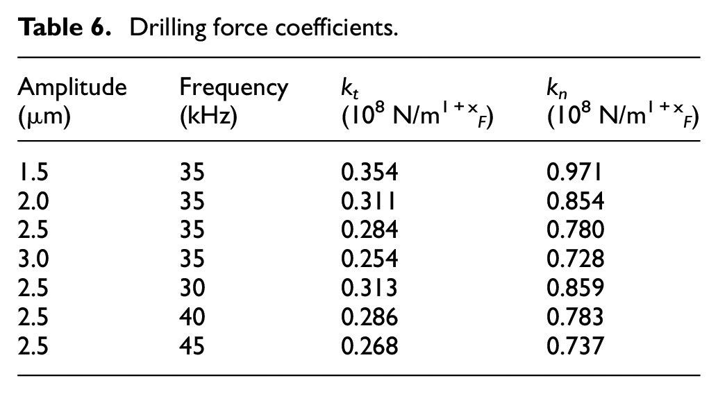
Figure 11(a) shows the stable lobes under different amplitudes. With the stable lobes as the boundary line, the upper area is the unstable drilling region, and the lower area is the stable one. The conditions of the drilling experiment were f = 35 kHz, A = 2.5 μm, n = 1500 r/min, cutting width a p = 6 mm, falling in the stable drilling area. There are two lobes in the figure, with the lowest point as the boundary, and the rectangular area below is the unconditional stable region. Figure 11(b) shows that as the amplitude increases, the unconditional stability area expands from 1.05 mm to 1.50 mm when the amplitude increases from A = 1.5 to 3 μm, and the growth tends to be linear with a change rate of 0.3 mm/μm. Similarly, it can be seen from Figure 12 that with the increase of vibration frequency, the unconditional stability region is on the rise as a whole. But the rising range is small, only expands from 1.20 to 1.38 mm when the frequency increases from f = 30 kHz to f = 45 kHz, and the average change rate is only 0.012 mm/kHz. Moreover, there is almost no change in the unconditional stability region in the vibration frequency range of 35 to 40 kHz. Therefore, in order to expand the unconditional stability region, it is more efficient to increase the amplitude than to increase the frequency.
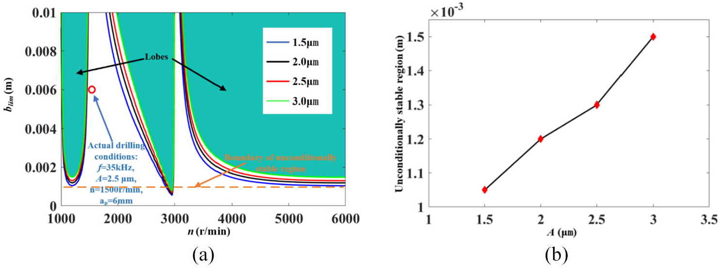
Stable lobes at different amplitudes (f = 35 kHz): (a) stable lobes and (b) trend of unconditionally stable region.
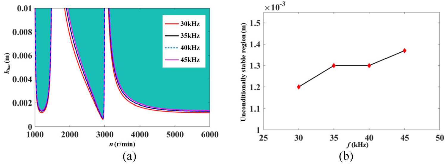
Stable lobes at different frequencies (A = 2.5 μm): (a) stable lobes and (b) trend of unconditionally stable region.
Through the stability analysis of Figures 11 and 12, we find that the axial ultrasonic vibration can effectively improve the stability region. The reason is that drilling itself will produce chatter which is not conducive to machining, while UVAD is characterized by intermittent cutting, which can effectively improve chip breaking rate, reduce drilling force, and effectively suppress chatter. 30
Conclusion
In this paper, the dynamical properties about UVAD of TiBw/TC4 composite materials is investigated. The following conclusions are drawn from the study:
(1) The deformation of the drilling system is simplified into a spring damping system. The dynamic model of single directional three-degree-of-freedom drilling system is established by combining the modal and dynamic parameters obtained by modal and drilling tests, with the results from axial drilling force prediction model.
(2) The vibration distribution of tool is obtained by the analysis of the vibration drilling model. The comparison of tool vibration curves obtained from drilling tests shows that the average values of the measured and fitted amplitudes are 0.1124 and 0.1151 mm, respectively, with a difference of 2.402%, which verifies the feasibility of the model. Meanwhile, it is found that the amplitude of the tool and the axial force of the drilling are consistent on the graph.
(3) The stability analysis of the machine in UVAD shows that the amplitude of the ultrasonic vibration has a significant effect on the processing stability. Moreover, as the amplitude increases, the unconditional stability area expands linearly at a rate of 0.3 mm/μm. Similarly, there is a positive correlation between vibration frequency and the unconditional stability area, but the rate of change is only 0.012 mm/kHz. Therefore, increasing the amplitude should be considered first in expanding the unconditional stability area.
Footnotes
Appendix
Declaration of conflicting interests
The author(s) declared no potential conflicts of interest with respect to the research, authorship, and/or publication of this article.
Funding
The author(s) disclosed receipt of the following financial support for the research, authorship, and/or publication of this article: This work was supported by the National Natural Science Foundation of China (Grant No.51775260,51705236), the Six Talent Peaks Project in Jiangsu Province of China (Grant No.GDZB58), the Qing Lan Project in Jiangsu Province of China, the Postgraduate Research & Practice Innovation Program of Jiangsu Province (SJCX19 0500).