
Abstract
Due to its numerous advantages such as reduction of machining force and surface roughness, ultrasonic-vibration assisted turning process has been extensively investigated. In the present paper, a new vibration analysis has been done and it has been shown that in the case of rigid workpiece or stable cutting ratio, negligible diametrical error is created by tool vibration in vibration turning which is not present in conventional turning. On the other part of the study, flexible workpiece has been considered and workpiece deformation has been investigated. It has been shown that in this case, the cutting ratio experiences an increasing trend from spindle to free end of one-end fixed workpiece. It has been also shown that the experimental results are in good agreement with analysis. Workpiece diametrical error in conventional turning is about twice in vibration turning.
Keywords
Introduction
In ultrasonic-vibration assisted machining (UVAM), high-frequency vibrations are added to conventional motion of cutting tool. 1 Reduction in average cutting forces, 2 tool wear3,4 and improvement of surface roughness 5 and heat tool effects 6 and increasing equivalent stiffness of the machining system, 7 are some of the advantages of this process. Many researcher studied influence of machining parameters on this process such as Khajehzadeh et al. 8 who have worked on residual stress in ultrasonic-vibration assisted turning (UVAT) and shown percentage intensity of ultrasonic power effects on generation of residual stress. These advantages have also been seen in other machining processes. 9 The vibration can be imposed in different directions and each one has its advantages. 10 The cutting ratio is the main parameter in vibration cutting. It should be noted that the underlying reason for reduced cutting forces in UVAT is the alternate separation and reconnection of tool from and to the cutting zone per each cycle of vibration. The cutting ratio is defined as the ratio of the cutting duration in each cycle of the vibration to the total cycle time. 11 One of the problems encountered in both the conventional turning and UVAT is the workpiece’s diametrical error being created during the machining process due to the relative movement between tool and workpiece. Different methods have already been employed for the analysis of the workpiece’s elastic deformation and the ensuing diametrical error, in CT. Among them can be named the finite difference 12 and static 13 method, FEM,14,15 experimental model 16 and Neural network. 17 The author of the present paper has investigated the diametric error of workpiece in both CT and UVAT.18,19 However, the effect of tool vibration on the cutting ratio was not investigated. In order to study the vibration of a machining workpiece, the vibration model of a beam under the moving loads can be employed. Quyang in 2011 20 has reviewed the research work carried out on this subject and subsequently reported the results of his own study on the dynamic behavior of a Timoshenko beam subjected to a three-dimensional axially moving force. The developed model represents the basic features of CT with the cutting tool moving on the surface and along the axis of the workpiece. In UVAT process, in addition to the elastic deformation resulting from flexible tool-workpiece interaction, the tool vibration is also responsible for the relative movement between workpiece and tool. Therefore, rigid workpiece will be considered first and diametrical error due to tool vibration is obtained. Then, based on theories of vibrations, a deformation model for workpiece ahead of tool caused by machining forces is presented. In the present paper, minimum boundary conditions are considered, that is, workpiece is fixed to spindle (no tailstock has been used) and initial conditions are zero. Since spindle is more rigid than other parts in workpiece-tool system, it has been considered as rigid. By using these assumptions, the effect of workpiece deformation on the cutting ratio is obtained and the equations of workpiece deformation are derived. In order to verify the results of theoretical analysis, experimental tests have been conducted on diametrical error.
Machining and non-machining force and times in UVAT
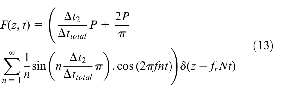
The relation for cutting force can be obtained by Fourier series in the following form 21
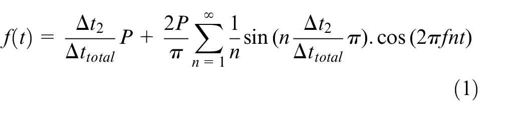
Where P is the maximum of periodic cutting force;
Absolute values of
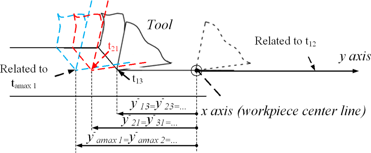
In this figure
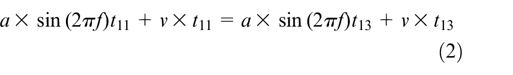
Where v is cutting speed and a is tool vibration amplitude.
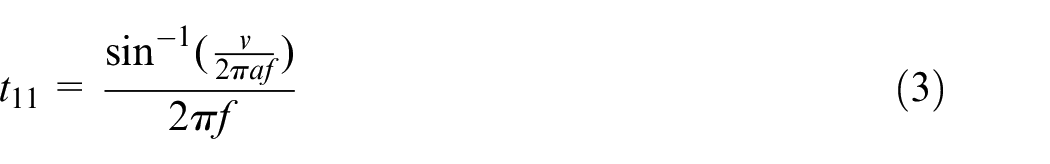
The corresponding relation for
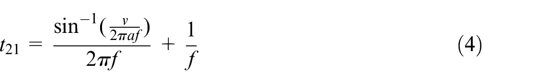
Therefore, cutting ratio becomes:

D is the initial diameter of workpiece and
When cutting tool clamped under workpiece center as an amplitude, the extended profile of workpiece and the previously mentioned parameters can be presented (in the exaggerated form) as in Figure 2:
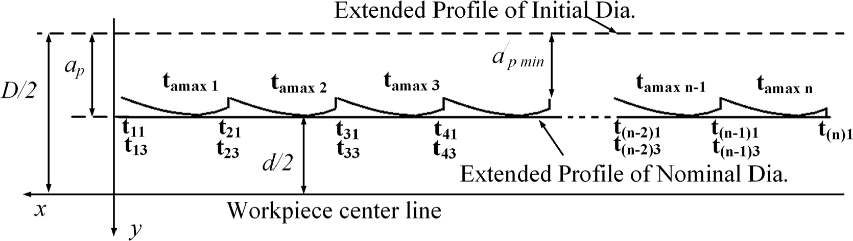
Extended profile of workpiece surface.
Equation (6) and Figure 2 mean that the cutting tool vibration proper produce diametrical error without even considering the flexibility of the workpiece. This can be a serious disadvantage of vibration assisted machining. However, several examples are presented in the following section which illustrate that the resulting error (
Some examples
By calculating

In the equation (8),
Effects of vibratory tool on maximum height of workpiece profile error and cutting force.
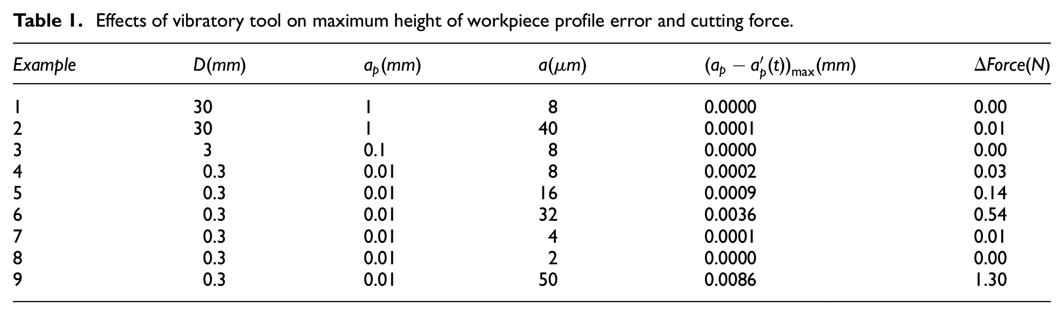
This table shows that tool vibration slightly increases diametrical error of rigid workpiece and reduces its cutting force.
Workpiece vibration analysis due to machining force
One-end clamped workpiece was considered for machining process. By using Hamilton principle, the equation for lateral motion of Euler-Bernoulli beam is obtained through minimizing the time integral of the difference between kinetic and potential energies which is as follows: 25
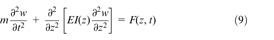
Where E is workpiece modulus of elasticity, m is mass per unit length and
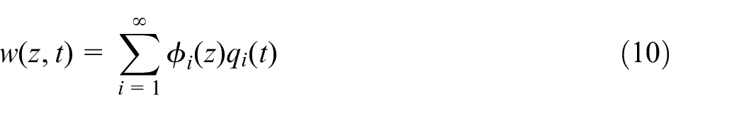
where
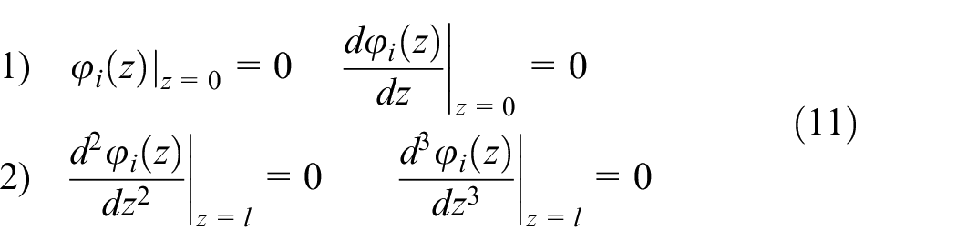
By applying these boundary conditions, mode shapes
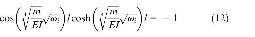
Where
where
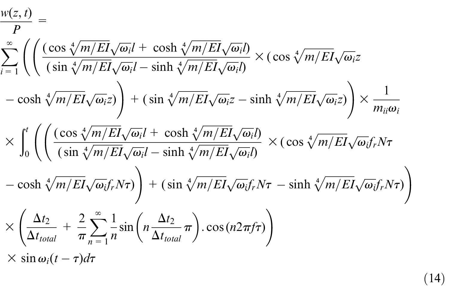
In this relation, except maximum vibration turning force (P), all other parameters are known. Therefore, this has been extracted from the rest of the equation. This makes the comparison with CT more easily. This relation is applicable for investigation of workpiece deformation in tangential and radial directions. P is the maximum cutting force and since it cannot be measured from experimental tests (due to high speed and high frequency), finite element analysis has been used instead. The results show that the value of P is very close to that in CT, therefore, here in order to compare UVAT and CT processes and investigate the effect of tool vibrations, the experimental results of CT has been used instead of P. The last natural frequency which is considered in analysis should be larger than tool vibration frequency. This is due to the fact that if tool vibration frequency is larger than all frequencies of natural modes, then one cannot expect that mode of vibration frequency would be excited. On the other hand, if too many modes are considered, computational relations will become several times larger which consequently makes it impossible to solve the problem by available computers. Also, by increasing number of modes, their effect on solution will diminish. In order to solve equation (14), first it is needed to derive natural frequencies from equation (12). There isn’t any analytical solution for equation (12), so, numerical solution should be used. Maple 14 software has been used for that purpose. If it is assumed that workpiece is from Aluminum 7075 (density of 2823 kg/m3 and modulus of elasticity
First 10 natural frequencies (in Hz).
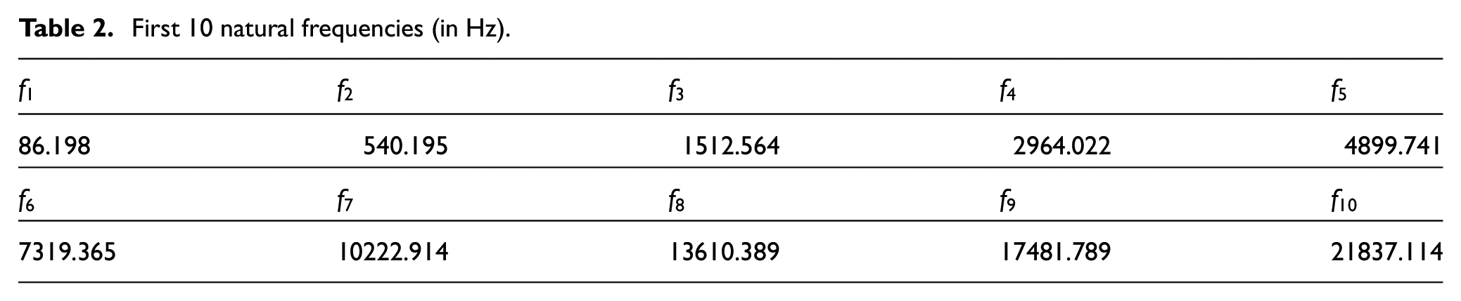
If it is assumed that the vibration frequency of tool is in ultrasonic ranges (20 kHz) the frequency of 10th mode is greater than 20 kHz. Therefore these 10 modes have been considered in the analysis. Through numerical solution of equations (4) and (5) in Maple, the graph of
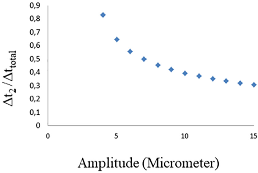
According to Figure 3, for a vibration amplitude of 8 μm,
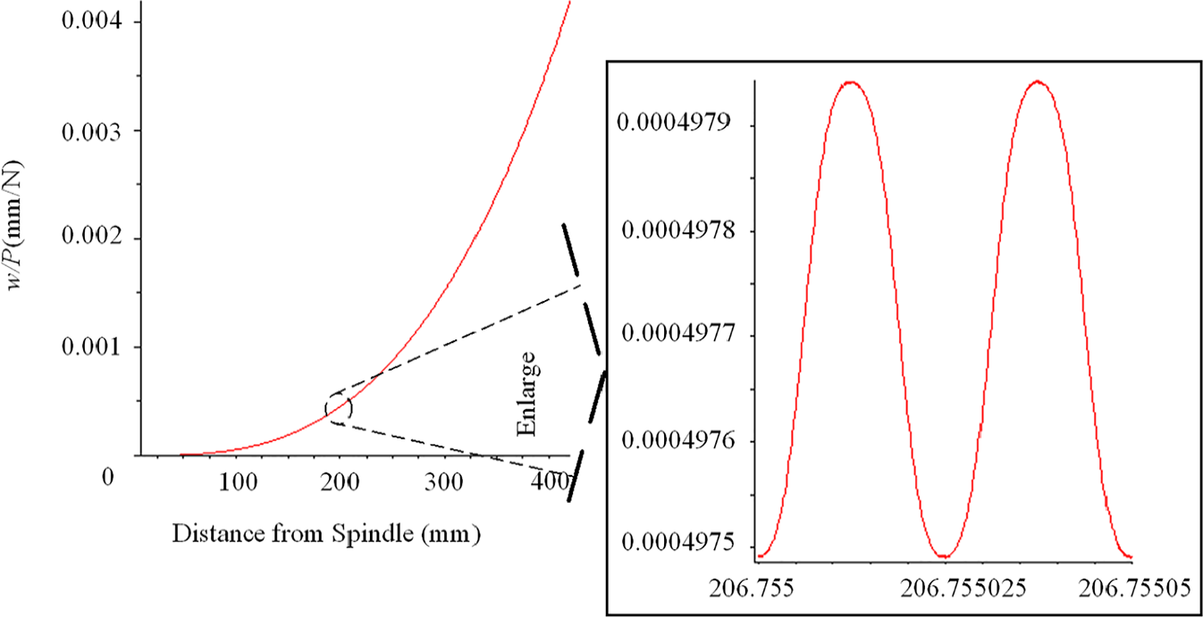
Ratio of workpiece deformation to maximum cutting force along workpiece (
In the Figure 4, a part of the main curve (at distance from 206.755 to 206.75505 mm) has been magnified. (Distance from two vibration peaks are
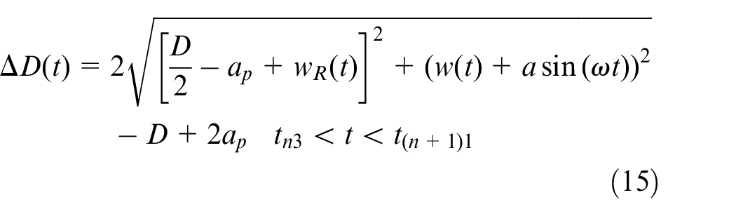
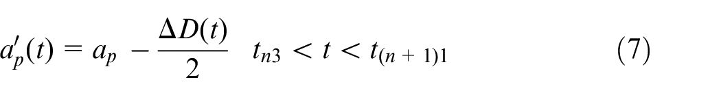
Therefore, by determining the start time of machining and end of tool movement in each pass and putting these times in equation (15), minimum and maximum of diametrical error can be obtained. From these two times, the time at which tool arrives to its end is when sinusoidal curve of tool vibration has a positive extremum (if each cutting pass is denoted by n, conditions 16 hold).
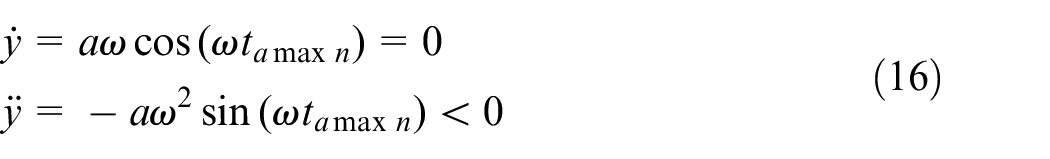
From these relations, the times at which tool reaches to its maximum amplitude in each machining pass can be formulated in the following form:
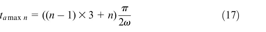
Thus, only machining start time (
The relation 15 shows the Increasing amplitude (a) cause increase in diametrical error and increasing ultrasonic frequency (more than 20 kHz), didn’t change workpiece deformation (
Determining cutting times by considering workpiece deformation
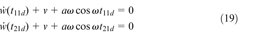
If the time for the start of the separation process for a flexible workpiece in first pass and second pass are respectively
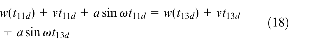
The times of start of Separation (The
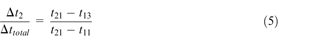
Similar to equation (5), cutting ratio (
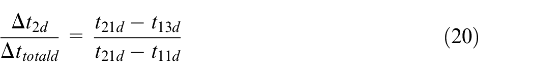
From a distance of 12.5 mm to 420 mm along workpiece and in space intervals of 2.5 mm, and by using equation (20) and considering workpiece deformation due to machining forces, the ratio of cutting time to period along workpiece has been obtained and shown in Figure 5.
Cutting ratio by taking into account the workpiece deformation (
As it is clear from the figure, as the distance from spindle and subsequently deformation increases, the distance between maximum and minimum values of
The most important parameter in this process is this value which influences machining conditions. (Even small) changes in this parameter can lead to significant effects on stability of the process and as it has been mentioned earlier, it directly influences on force. Therefore, the schematic of cutting force can be illustrated in the Figure 6:
Effect of workpiece springback on cutting ratio.
Experimental test
In order to experimentally investigate the spring-back in vibration turning, a setup has been prepared. The necessary vibration has been provided by a Steckmann GmbH generator and transducer and has been applied on tool in cutting direction. For force measurement, a Kistler dynamometer (model 9257BA) has been employed. A TME40 CNC turning machine has been used for the turning process of AL7075 cylindrical workpiece. The vibration amplitude and frequency were 8 micrometers and 20 kHz respectively. A titanium horn designed and fabricated for concentering and transferring mechanical vibration to cutting tool. A Sandvik VBMT 160404 tool has been also used. Clearance angle was 5°, rake angle was 4°. Cutting depth 1 mm, feedrate 0.1 mm/rev and spindle speed 300 rpm have been adjusted. Workpiece length was 600 mm from which 500 mm has been rest out of the spindle.
For the workpieces used in CT and UVAT to have the same mechanical properties and initial deformations, they have been chosen from a 6 mbar. The two ends of this bar has been cut 0.5 m, therefore, the initial workpiece diameter along its length has been found to be
Where
Comparison of experimental and analytical results
In order to compare the experimental data with analytical results, the final diameter of workpiece and real cutting depth have been used in the present paper.
Deriving diametrical error from analytical relations and comparing CT and UVAT processes
In the performed analysis, diametrical error can be obtained from calculating elastic deformation of workpiece in cutting and radial directions. In order to provide a comparison between analytical and experimental results, the obtained forces from CT experiments in each workpiece section have been replaced in equation (14) equation. If
Diametrical error in CT is calculated from equation (21) and maximum of diametrical error in UVAT can be obtained by substituting elastic deformations of workpiece (equation (22)) into equations (15), (17), and (18). The percentage of reduction of diametrical error in UVAT process in comparison with CT process with respect to distance from spindle has been shown in Figure 7.
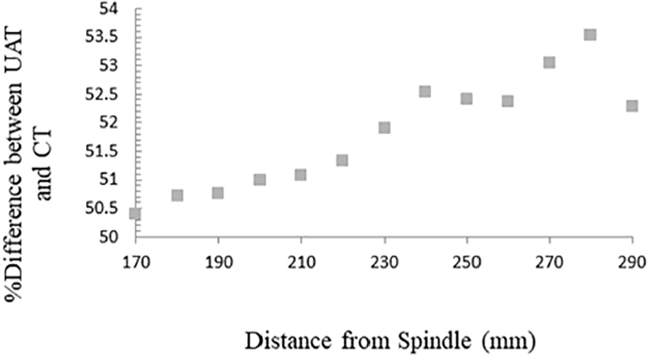
Percentage of reduction of diametrical error in UVAT process in comparison with CT process with respect to distance from spindle (
Figure 7, shows the percentage of reduction of diametrical error in UVAT process in comparison with CT process increases with increasing the distance from spindle.
Comparison of experimental and analytical results by taking diametrical error into account
In order to compare experimental and analytical results, final diameter of workpiece has been used. By using the data of the authors’ previous article,
21
Figure 8 has been drawn. This figure shows the percentage of error between experiments and analysis for both CT and UVAT processes when final diameter of workpiece (
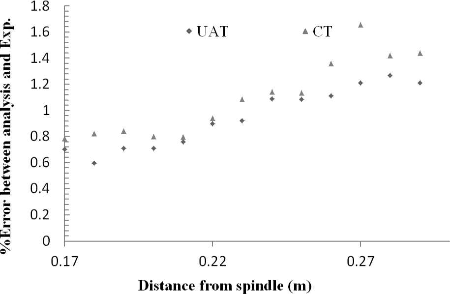
Comparison of percentage of diametrical error between analytical solution and experimental data by taking final diameter of workpiece into account (
As it is obvious from the figure, the discrepancies between analytical and experimental results are small and it can be said that this discrepancy becomes less and less as we move toward spindle. Also, the error between analytical and experimental results in UVAT is less than in CT. Therefore, in order to avoid the error due to deformation of workpiece, cutting depth should change along workpiece and a depth equal to (
Conclusion
In the present study, it has been shown that tool vibration causes negligible diametrical error in ultrasonic vibration assisted turning of a rigid workpiece. It has been shown that vibration amplitude of workpiece in UVAT process is much less than tool vibration amplitude and is close to static value. The contact and separation time of tool and workpiece and also machining time has been determined by taking into account the workpiece deformation. And it has been also shown that as workpiece deformation increases, the difference between maximum and minimum cutting time along workpiece increases which changes cutting force in each pass and finally leads to instability. Therefore, changes in the cutting ratio and its effects on stability of machining, can little affect the diametrical error. But both theoretical and experimental results show the average diametrical error of workpiece in the ultrasonic vibration assisted turning process is smaller than conventional turning.
Footnotes
Appendix
Declaration of conflicting interests
The author(s) declared no potential conflicts of interest with respect to the research, authorship, and/or publication of this article.
Funding
The author(s) received no financial support for the research, authorship, and/or publication of this article.