
Abstract
This paper presents a methodology for precision manufacture of a nozzle using the hybrid laser powder-bed fusion (L-PBF) technology. A new distortion predictive model for hybrid L-PBF was developed using finite element techniques. The model was validated against experimentally measured distortion using optical scanning. The validated model was utilised to mitigate distortion by applying additional stiffeners to the nozzle geometry where the distortion was reduced by 60% to acceptable tolerance of ± 200 µm. Micro-milling trials were conducted to identify optimum cutting parameters delivering high material removal rates while maintaining the average surface roughness of less than 1 µm. Finally, a nozzle with reduced distortion and desirable surface finish was manufactured, which has been used in industrial research context for process and product development of food products.
Keywords
Introduction
Hybrid powder-bed additive manufacturing (AM) is a relatively new technology that combines research challenges from two manufacturing processes, laser powder-bed fusion (L-PBF) and micro-milling. The micro-milling process has been researched where the physics and the associated challenges have been addressed in the past, including cutting forces,1,2 tool dynamics and chatter,3,4 tool wear,5,6 thermal loads7,8 and associated effects of the process parameters on different materials. 9 There is also significant research conducted in L-PBF in the development of process parameters for different materials,10,11 understanding porosity and defects, 12 residual stresses and mitigation of distortion,13,14 design optimisation techniques, 15 powder behaviour and metallurgical aspects.16,17
Combining L-PBF and micro-milling into a single system increases complexity and generates more challenges and limitations. For instance, lubricants and coolant technologies cannot be applied during milling due to the surrounding powder and the possibility of contamination. Another limitation is milling access for certain geometrical areas, such as overhang regions, back-tapered surfaces and enclosed features due to the nature of the 3-axis micro-milling process. Furthermore, the design of the component must consider all aspects of the hybrid process and not just AM design rules, overhangs and sloped features, but also how supports could influence the access of the machining tool. 18
Research has been conducted in hybrid direct energy deposition (DED) combined with conventional Computer Numerical Control (CNC) machining. Lorenz et al. 19 conducted a literature review on hybrid systems. They concluded that the hybrid DED-CNC technology is still not mature enough to offer industry cost effective solutions. There are a number of high value repair applications, such as the turbine blade repair, where the technology can reduce costs associated with replacement or maintenance. Soshi et al. 20 demonstrated that producing functional moulds is achievable using DED and CNC machining. Flynn et al. 21 conducted a detailed review on the hybrid DED and CNC machine tools. They concluded that the transformation from research to the commercial arena has been at a gradual pace since 1990, mainly due to the geometrical and compositional complexity of the parts that drives the cost-effectiveness of the process.
Post-finishing milling on impeller produced by L-PBF was conducted by Yaghi et al. 22 The key challenges they faced was the positioning of the part and the access to internal surfaces. The hybrid L-PBF has an advantage as the positioning is fixed in the system. Also, internal surfaces can be machined. A drawback of the hybrid L-PBF is that due to the micro-milling, chips are generated and mixed with the powder. In micro-milling, the feeds per tooth are relatively low and comparable to the size of the powder, which might be acceptable for applications where the structural integrity is not critical. Nakita et al. 23 used the hybrid L-PBF Matsuura Lumex Avance-25 to fabricate denture clasps. They reported an improved surface finish on the machined surface compared with the conventional casting technology used to fabricate Co-Cr and titanium denture clasps. Mutua et al. 24 conducted an experimental process optimisation study for maraging steel on the Lumex Avance-25 laser system.
Hybrid L-PBF has the potential to open new horizons for innovative nozzle design in industry. By simultaneously building and machining, complex 3D structures containing internal features and channels can be produced using industry standard materials more efficiently than with the use of conventional methods. This could lead to new products reaching the market place and consumers. 25 To unlock the design freedom needed for the next generation of nozzles, several challenges need to be addressed, including:
design for hybrid powder-bed AM;
high speed machining performance optimisation for surface quality and tool wear optimisation;
advanced modelling and simulation support for process and product development;
maturation of the hybrid powder-bed AM technology and its adoption in industry.
The AM market is growing, and it is expected to be a key enabler for high value manufacturing components, including complex nozzles in the food sector. 26 Therefore, the aim of this work is to develop a new methodology for precision manufacture of nozzles with high dimensional accuracy and surface tolerance requirements addressing some of the above listed challenges. The methodology is applied to an application in the food sector where the prevention of hygienic problems and bacterial growth is essential.
Methodology
The methodology in this study is shown in Figure 1. Once the geometry of the nozzle is designed and ready for manufacture, a process model is utilised to predict and mitigate distortion. A new process model has been developed that has an additive step and a subtractive step to simulate the full hybrid process. The additive portion of the process model is built upon the L-PBF model for stainless steel 316 using the inherent strain approach adopted into a finite element model, previously presented by Yaghi et al. 22 The subtractive step is modelled by removing elements from the stiffness matrix of the finite element model. The predicted distortion from the model has been validated against experimental data. The model has been then used to mitigate the distortion in order to meet geometrical tolerances.
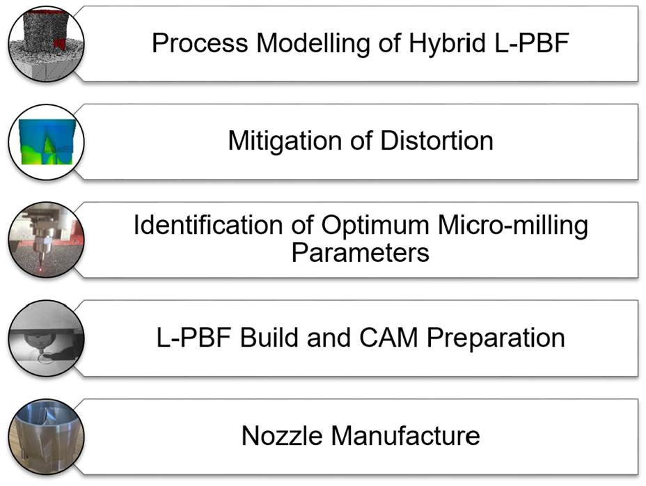
Methodology diagram.
The next step of the methodology is focused on the selection of optimum micro-milling process parameters to deliver high material removal rates at specified average surface roughness (Ra). The Ra for the current nozzle application for bacteria growth prevention is to be less than 1 µm. To achieve this Ra target, a design of experiment (DoE) is developed to experimentally investigate and measure the surface roughness for different process parameters and tools. The aim of the experimental trials is to identify the process parameters that deliver the highest material removal rate and achieve Ra less than 1 µm.
Next, the nozzle geometry and the optimum micro-milling parameters are used for the hybrid L-PBF build preparation that includes slicing of the geometry and creating a toolpath for the laser. Also, a toolpath is generated for the micro-mills using the optimum process parameters. Finally, the nozzle is manufactured on the Matsuura Lumex Avance-25 hybrid system. The outcome of this methodology is a final produced nozzle that meets dimensional and surface finish requirements.
Hybrid L-PBF process model
The hybrid L-PBF process model is constructed as described by Yaghi et al. 22 using the inherent strain approach, which in turn comprises methodologies that were adopted from Afazov et al. 13 and further developed to include the subtractive process invoked by the micro-machining, which is the innovative contribution in the presented model. This method requires a calibration specimen to be produced to validate the additive manufacture aspect of the model, including material assumptions and prescription of inherent strain values. The mesh is offset in all directions to add a stock material of 0.15 mm to all machined faces. This is the typical approach for scaling the geometry on the Matsuura Lumex Avance-25 to account for the material that is to be machined. Enough material needs to be removed to eliminate any surface defects, such as surface roughness and porosity, which also depends on the tooling used for the removal.
Subsequently, the element birth/death technique is utilised in the model beyond adding material to also remove the material when required, thus modelling the additive and subtractive processes during the hybrid L-PBF build. The Matsuura Lumex Avance-25 machine typically deposits ten 50 µm layers before calling the machining operation. The machining operations have various axial steps and stock depths depending on the tooling used and if the operation is semi-finishing or finishing (see Figure 2). The models are set-up with a lumped layer sizes of 0.5 mm, capturing the 10 deposited layers (birthing elements) and the removal of material during micro-machining (death of elements). Furthermore, the segregation of material between the scaled material (stock material) and the component is accounted for during the modelling of the micro-machining only, that is, the material is deposited simultaneously as one layer and then the stock is removed prior to depositing the next lumped layer. The finite element mesh of the nozzle used for the validation is shown in Figure 3.
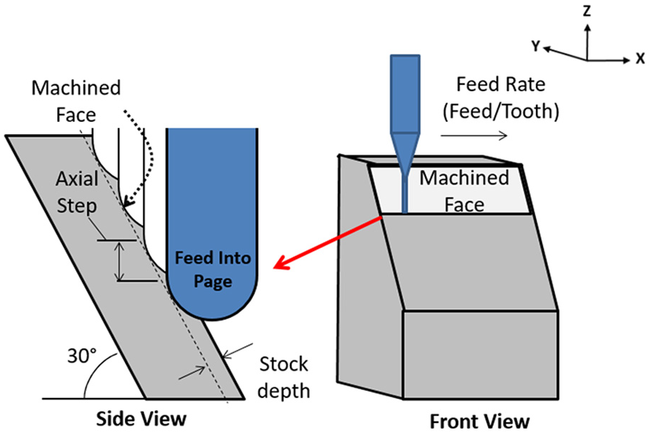
Definition of machining process in hybrid L-PBF.
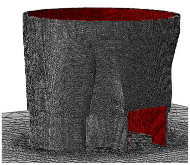
Finite element mesh of the nozzle used for process validation (the red colour shows the machined surface).
Once the component is fully deposited and micro-machined, the substrate is removed via wire electrical discharge machining, which is simulated by removing the elements associated with the substrate. The residual stresses are then re-balanced, and the final distortion is analysed by aligning it to the as-designed CAD to compute the surface deviation. Finally, the model is compared to a physical specimen to validate the modelling technique employed in this research.
Micro-milling trials: Experimental set-up
Micro-milling trials are conducted on the Kern Evo Ultra Precision CNC Machine to identify process parameters that can produce acceptable surface finish on the nozzle while maintaining a high material removal rate. The machining tests are performed on AM built stainless steel 316L samples produced on the Matsuura Lumex Avance-25 hybrid system. After each trial, the machined surfaces are measured using the Alicona G5. The design of experiment for the cutting trials is shown in Table 1. In the cutting trails, the micro-milling tools with radii of 1 and 0.5 mm are tested, as these tools have been used for the nozzle manufacture. A spindle speed of 40,000 rpm is selected for the cutting trials. The feed rate and the axial step are varied to investigate their effects on the surface roughness. The minimum selected feed rate for the experimental investigation was 2 µm/tooth in order to prevent any ploughing in micro-milling.
Process parameters for the cutting trials.
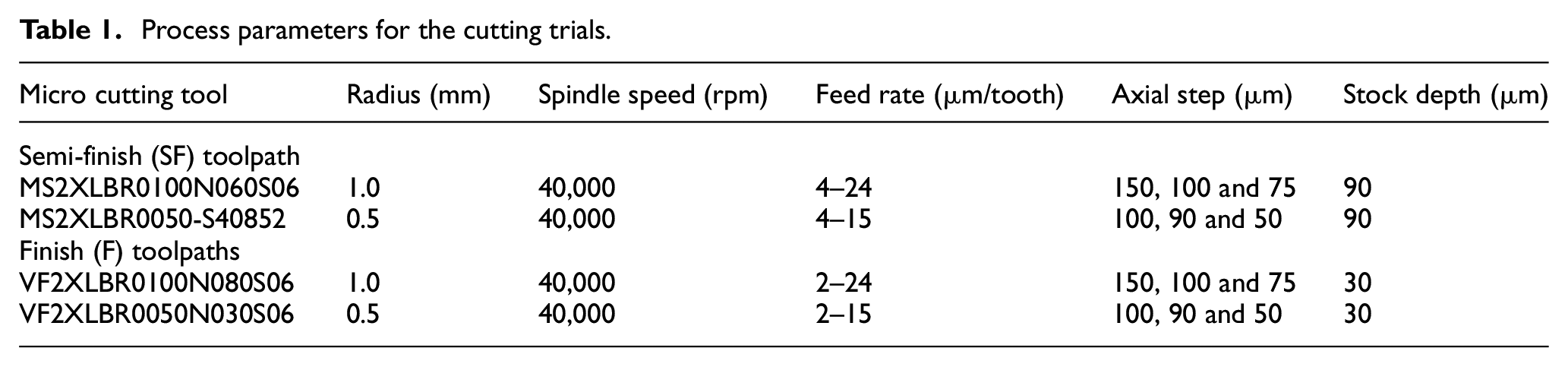
Figure 4 shows the machining trials set-up on the Kern Evo. A workpiece produced by L-PBF is mounted on a Kistler load cell, which in turn is mounted on a fixture attached to the Kern Evo micro-machine bed. The cutting tools are clamped with a 3 mm collet and loaded into the Kern Evo machine. The tool stick out has been set to 22 mm from the tool holder edge for all trials.
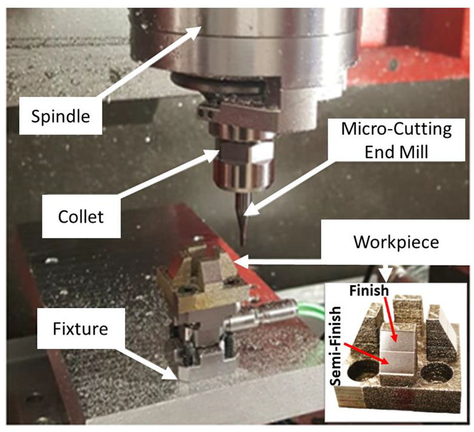
Kern Evo machining trials setup with a workpiece produced on the Matsuura Lumex Avance-25 hybrid system.
The machining trials are conducted on Kern Evo using AM test samples produced on the Matsuura Lumex Avance-25 hybrid system (see Figure 4). The faces of the samples are set to a 30° angle to represent most of the inner surfaces of the nozzle, while maintaining a planar surface for easy surface analysis. During machining, each inclined surface of the workpiece is machined with a single set of process parameters. The machine toolpath follows a down-milling Zig pattern where the tool engages and retracts with the workpiece creating a sequence of parallel linear passes that ensures cuts are in the same direction. First, a semi-finish tool is used to rough out the entire surface, then the finishing tool finishes half of the semi-finished surface. Only half of the face is finished so that both finished and semi-finished faces can be measured.
Surface measurements of the machined faces are conducted after each trial. The Alicona G5 is used to measure the surface roughness of the finished and semi-finished sample faces. For each scanned face, three virtual trace measurements are taken in each the feed and cross feed direction. Surface Ra values are recorded for each trace, and a mean Ra value is obtained in the cross and feed directions.
Results and discussion
The results of the methodology are detailed in this section. This includes the process of modelling and correcting the part geometric design based on distortion, and the process of evaluating and selecting the optimal machining parameters.
Hybrid L-PBF modelling results
In order to calibrate the part distortion model, a double cantilever beam was first manufactured and the distortion, once removed from the substrate, was measured by a shadowgraph imaging along the top surface of the beam between points A and B, as depicted in Figure 5. After applying the calibration in the finite element model, the measured distortion was correctly predicted using yield stress of 600 MPa, modulus of elasticity of 200 GPa, Poisson’s ratio of 0.27 and compressive inherent strains of −0.0032 applied in the three directions of the Cartesian coordinate system. It should be noted that no subtractive steps were included when producing the double cantilever beam because the main purpose was to calibrate the material assumptions and the applied values for the inherent strain.
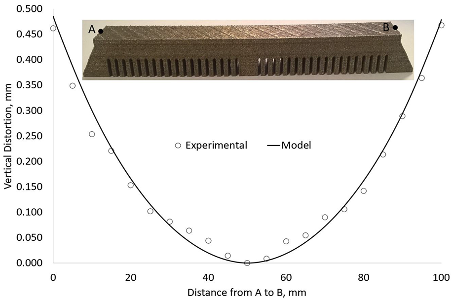
Distortion measurements and calibration of L-PBF process model on a double cantilever beam.
The calibrated inherent strain values from the double cantilever beam was used in a full 3D hybrid L-PBF process model of the original nozzle design. The original nozzle design was first manufactured on the Matsuura Lumex 25 without using supports. Once built, the nozzle was cut from the substrate by wire electrical discharge machining and then optically scanned using the optical scanning technology GOM. The scanned surfaces were aligned to the desired geometry and the surface deviations were calculated. The same approach was used for the finite element predicted final surfaces, which were exported in the form of surface mesh. The two surface deviations were then compared against the as-designed CAD, as shown Figure 6. It should be noted that only the inner surface of the nozzle was machined, which was accounted for in the finite element model. By comparing the distortion trends and magnitudes from the physical nozzle and those predicted by the finite element model, good agreement between the two plots can be seen. Thus, it can be concluded that the hybrid L-PBF process model is valid and capable of predicting distortion for the hybrid L-PBF. The distortion was generated due to residual stress induced by the L-PBF process and the material removal. The current model simulated both, the L-PBF build process and the bulk material removal. The model did not include the stresses at the surface due to the tool-workpiece interaction. Yaghi et al. 22 simulated and measured the effect of the surface induces stresses in machining of L-PBF produced 316L thin blades to be in the range of 20 µm. Therefore, the simulation of the tool-workpiece interactions was not included. Also, the assumption of grouping layers proved that this is a feasible assumption when the inherent strain is used with the appropriate calibration procedure. The cantilever beam was manufactured without any milling involved. This means that no chips were mixed with the powder in the build volume which was not the case for the manufacture of the nozzle. The results showed that the assumption made to ignore any effect of the chips in the powder is reasonable for the prediction of distortion.
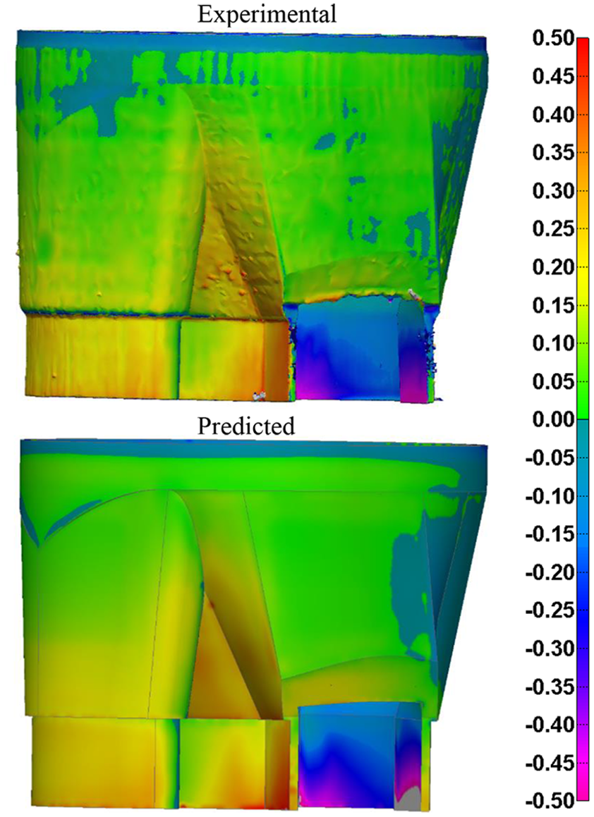
Comparison of surface deviation in mm for the original nozzle design.
The validated finite element predictive model enabled design changes to be rectified before the product was manufactured. The original nozzle design was deemed to be out of specification due to distortions in outlet of the nozzle exceeding 1 mm. To reduce the distortion, geometrical changes were applied to the nozzle design and the distortion was again predicted by the finite element model. As shown in Figure 7, the compensated design with two additional applied stiffeners at the outlet alleviated the distortion by approximately 60% at the bottom of the nozzle, with the entire nozzle being within the required tolerance of ±200 µm. This provided a confidence in the modified design for a successful build without the need for support structures as well.
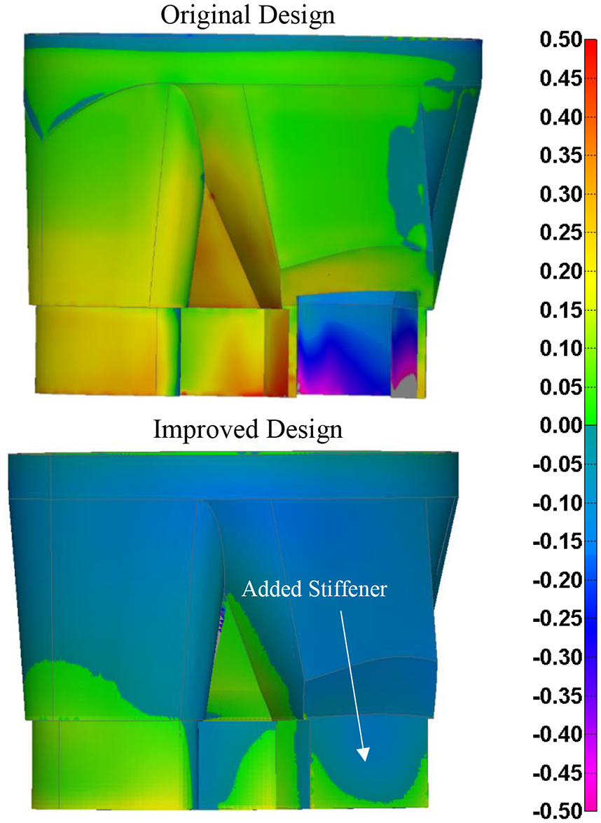
Comparison of predicted surface deviation in mm for the original and improved designs.
Surface roughness results of micro-milling trials
To determine an optimum set of machining parameters, the surface finish for all machined samples were analysed using Alicona G5 measurements. Figure 8 shows the resulting 3D and 2D output generated upon scanning, as well as the method for determining the Ra value. For each scanned face, three virtual trace measurements are taken in each the feed and cross feed directions. Surface Ra values are recorded for each trace as shown in Figure 8, and a mean Ra value is obtained in the cross and feed directions. The same method is applied to all micro-milled faces. Some machined surfaces contained flaws due to porosity as a result of the L-PBF process. To examine the effect of porosity in the AM builds, CT scans were carried out. A CT scan of L-PBF build samples is shown in Figure 9 where a porosity can be seen near the un-machined surface, as well as its reduction towards the inner direction of the material. The porosity on the machined surface was removed by machining deeper into the material. This demonstrates the practical reason why a stock material of 0.15 mm is needed. It needs to be noted that the machined samples were produced without the use of any milling operations in the hybrid system.
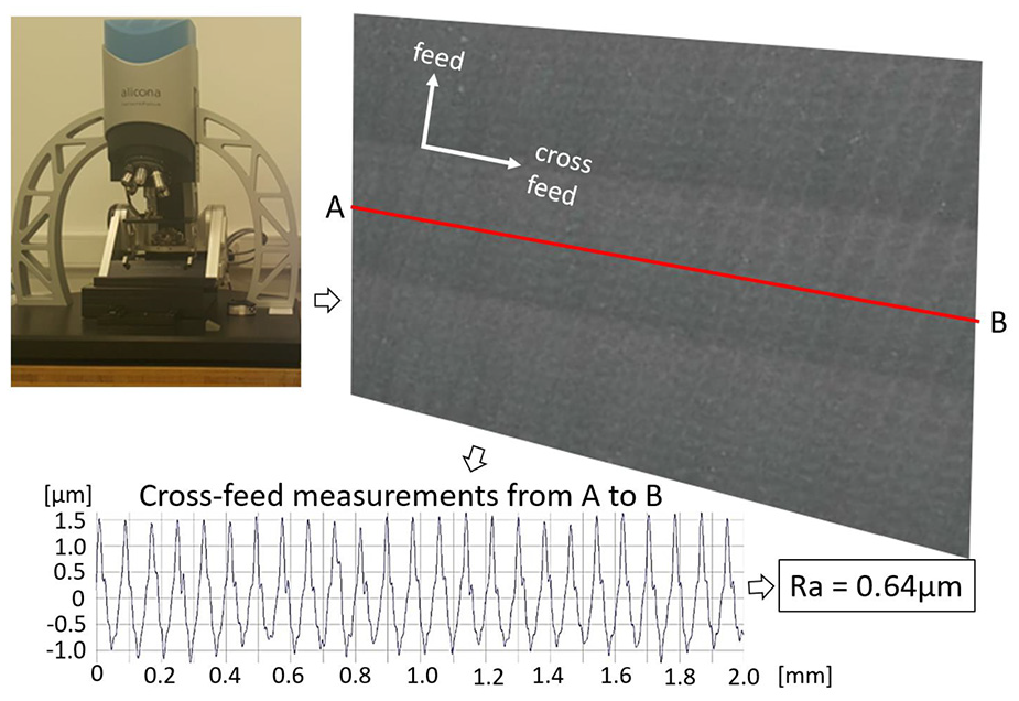
Illustration of the 3D and 2D morphology output of a scanned frame using Alicona G5.
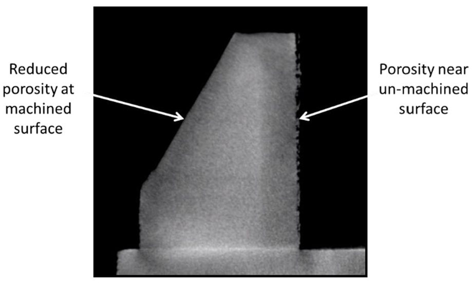
CT scan result an AM build sample with porous surfaces.
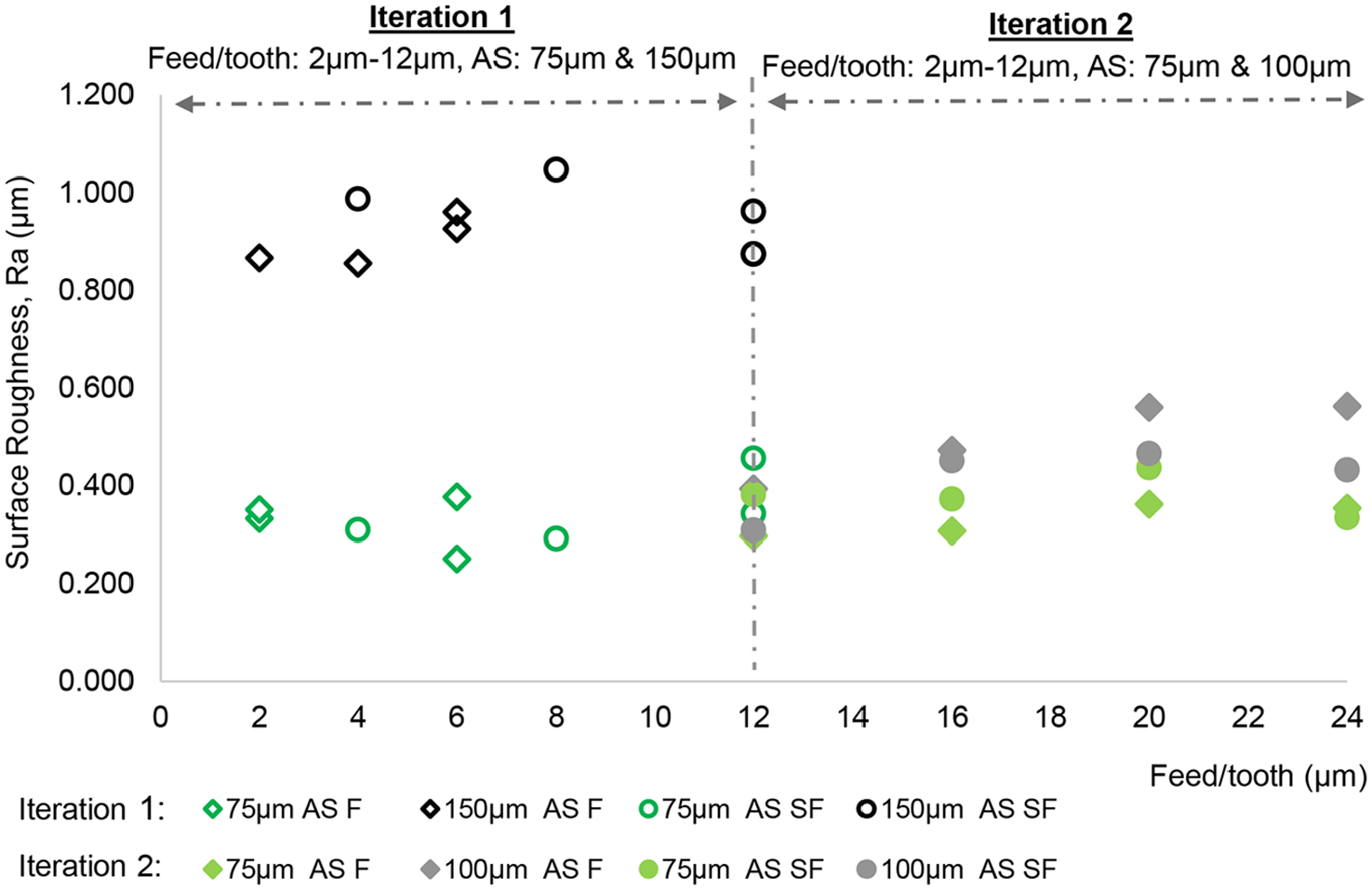
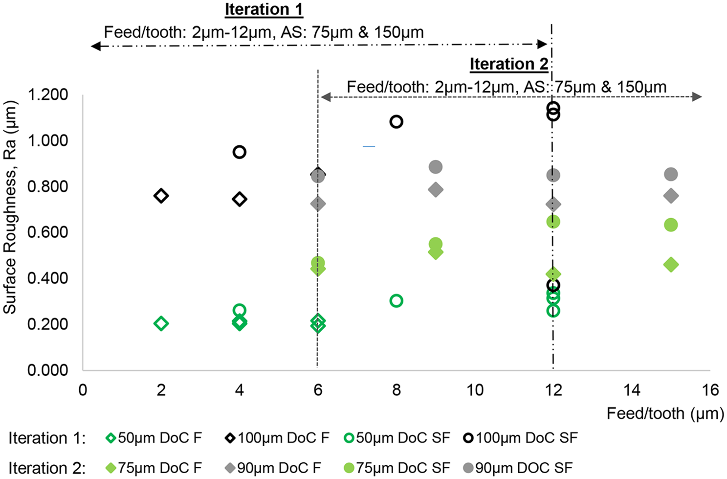
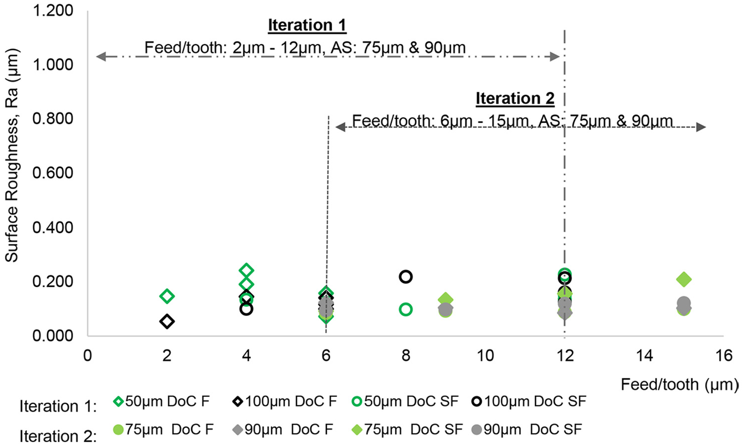
Resulting surface roughness (Ra) values in the cross feed direction are plotted over the range of feed rates and axial depths of cut in Figures 10 to 13 for the cutting tools with radii of 0.5 and 1 mm. Note that only cross feed surface Ra is emphasised here because the feed direction Ra measurements are negligible compared with the cross feed direction.
Cross feed Ra against feed/tooth for 1 mm radius tools.
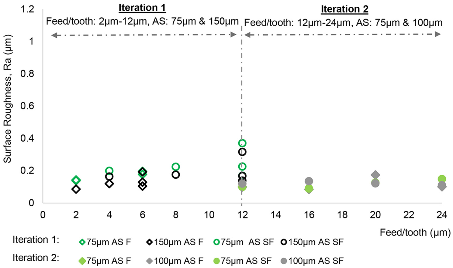
Feed Ra against feed/tooth for 1 mm radius tools.
Cross feed Ra against feed/tooth for 0.5 mm radius tools.
Feed Ra against feed/tooth for 0.5 mm radius tools.
Plots of cross feed Ra values for the R1.0 cutting tools show that the surface roughness generally increases as feed per tooth is increased from 12 to 24 µm. Despite this trend, maximum Ra values for parameters used remain well below 1 µm for all cases. Reducing the axial steps from 150 to 100 µm has shown that the maximum Ra value has decreased down to 0.563 µm, as shown in Figure 10.
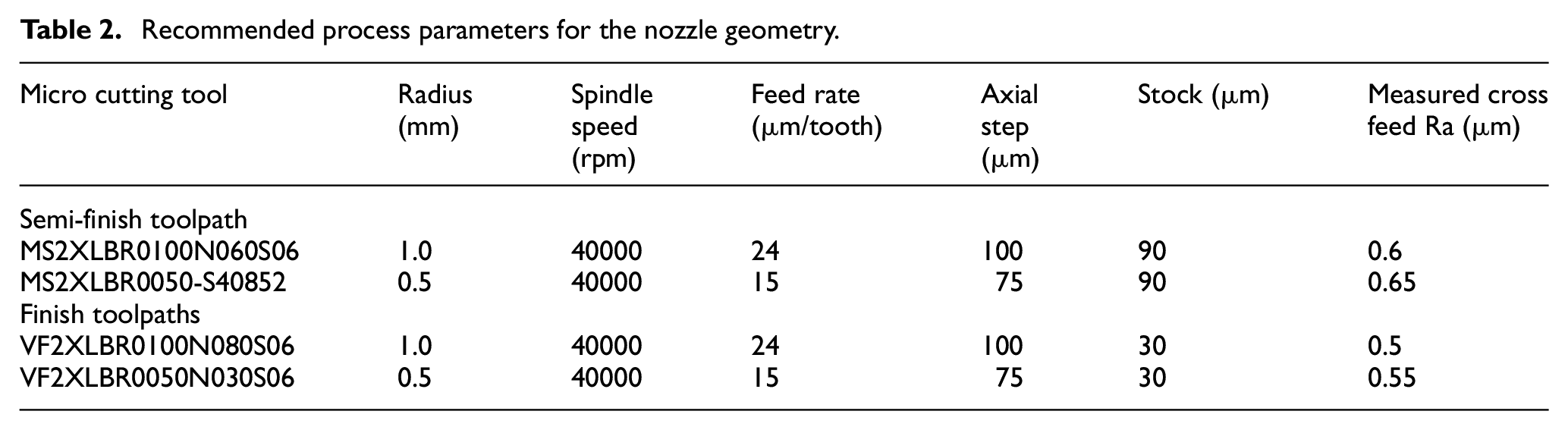
The Ra values for the R0.5 cutting tools show a similar trend, but with less defined effects of varied feed rate. The surface roughness increases by increasing the axial steps from 75 to 90 µm for both finish and semi-finish toolpaths. At 90 µm axial steps for the R0.5 tools, the surface Ra is close to the 1 µm target, averaging between 0.7 and 0.9 µm (see Figure 12). Following the analyses of the obtained results, optimum process parameters have been identified for machining the nozzle geometry as shown in Table 2.
Recommended process parameters for the nozzle geometry.
Manufacturing of a nozzle
To generate the part program, Lumex CAD and CAM systems were used to import the improved nozzle geometry. The geometry was then sliced into layers of 50 µm in order to create the tool-path for the 400W Yb fibre laser installed on the LUMEX Avance-25 hybrid machine. The optimum cutting parameters from Table 2 for roughing, semi-finish and finish were used to generate the tool-paths for the cutting tools. During the roughing cuts, the stock depth was 30 µm and the cutting tool interacted with the powder while cutting, which was not accounted for in the experimental trials. Nevertheless, the optimum parameters obtained for the semi-finishing tool were applied for the roughing cut. The first manufactured nozzle resulted in several lessons learnt. The first lesson learnt was that the semi-finishing tools were wearing too quickly when used for the roughing operation at 40,000 rpm. After further investigation it was found that reducing the spindle speed to 10,000 rpm improved the wear performance; however, it reduced the material removal rate. The second lesson learnt was that the finishing tools were breaking at negative incline wall angles as the neck of the tool was not relieved enough to allow for 75 µm axial step. The experimental trials were conducted at an incline angle of 30° (see Figure 3), which is appropriate for machining the internal surfaces of the nozzle but not the external surfaces with negative wall angles.
Considering the challenges in the first iteration, the following actions were taken in the second iteration. First, the roughing cut was conducted with the semi-finish tools at 10,000 rpm instead of 40,000 rpm, while keeping the recommended feed rates and axial steps from Table 2. Second, the finishing tools and recommended parameters were only used for positive incline angles, which was the case for the internal surfaces of the nozzle. All external surfaces of the nozzle were machined with a T-slot tool using spindle speed of 8,000 rpm, feed rate of 24 µm/flute and axial step of 100 µm. Third, it was conservatively decided to change the tools every 300 deposited additive layers (15 mm build height) to avoid any tool breakages due to wear. After considering all actions, the second iteration resulted in successful manufacture of a nozzle, as shown in Figure 14. The surface finish was inspected and no surface defects were observed. It was not observed that the chips from the milling operation have affected the surface quality. The nozzle was successfully fitted in a machine for deposition of ice cream where further tests for bacteria growth and other performance indicators, not reported in this study, were conducted.
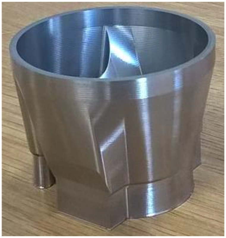
Manufactured nozzle using hybrid laser powder bed fusion.
The research work conducted in this study showed that the manufacturing of nozzles is feasible using the hybrid L-PBF process. The key challenge is to obtain the optimum process parameters and selection of cutting tools for different geometric features. The idea of using higher spindle speeds resulted in improving the material removal rate for some cutting tools applied on specific geometric features. As the material removal rate improved by increasing the spindle speed, the wear rate increased as well. The mitigation of wear rates in this study was conducted by using greater number of tools, which is not a cost-efficient option considering the cost of the micro-milling tools. The successes and lessons learnt from this study show that the machining parameters and selection of cutting tools need to be based on geometric features.
Conclusion
The following conclusions were derived from this research work:
The development and validation of the new distortion predictive model for hybrid L-PBF enabled the successful nozzle re-design, where the distortion was reduced by 60%;
The knowledge generated from the micro-milling trials was successfully used to understand how cutting parameters affect the surface finish and improve the material removal rates;
A nozzle design was manufactured with acceptable surface finish to prevent bacteria growth when the nozzle has been used in an industrial environment;
It was learnt that the selection of cutting tools for specific geometric features is crucial for the right first-time manufacture of complex nozzle geometries using the hybrid L-PBF technology;
The cutting tool wear at high spindle speeds needs to be further researched as well as the cost-effectiveness of the micro-milling process;
The hybrid L-PBF technology used in this work demonstrated that internal surface finishing of complex geometries can be manufactured with acceptable quality for the food industry.
Footnotes
Acknowledgements
The authors wish to acknowledge the High Value Manufacturing Catapult and its Forum+ Programme for the financial support of this research. The authors wish to thank Matsuura and Unilever for their in-kind contribution and technical support to the project. Thanks to Joseph Bellis from Matsuura who led the manufacturing of the nozzles.
Declaration of conflicting interests
The author(s) declared no potential conflicts of interest with respect to the research, authorship, and/or publication of this article.
Funding
The author(s) disclosed receipt of the following financial support for the research, authorship, and/or publication of this article: Authors received financial support for the research, authorship and publication of this research by High Value Manufacturing Catapult UK.