
Abstract
Austempered ductile iron castings (ADI) are characterized by the high strength and resistance to fatigue, impact, and wear. ADI mechanical properties are obtained by performing a heat treatment on ductile iron casting. Thus, the so-called ausferrite microstructure is achieved. However, heat treatment significantly affects ductile casting machinability. A precise determination of ADI microstructure, on the one hand, and to choose correct machining process parameters and tool wear control on the other, are essential to optimize cutting processes and for the introduction of ceramic inserts. Ceramics are an alternative to carbide tools. In this paper, ceramic tools for the dry turning of ADI castings are studied. Thus, different technical ceramics were analyzed, identifying the dominant wear mechanism and evolution. Tool wear rate magnitude was determined indirectly by the variation of cutting force along machining time. Finally, different tests helped to study ceramics wear sensitivity with respect to cutting parameters. Mixed ceramics of Al2O3 with TiC showed the best performance, followed by SiAlON ones.
Introduction
Ductile cast iron is also known as nodular cast iron or spheroidal graphite cast. The casting process and material grade were defined in the 1940s. Its superior properties are due to graphite spheroids in metal matrix, different from gray casts in which graphite is in the form of layers. Ductile casting maximum tensile strength can be 700 MPa, so the ductile type was widely used in all kinds of mechanical systems to reduce weight. Hence, any piece thicknesses can be reduced due to the superior mechanical characteristics of ductile casting.
Austempered ductile iron (ADI) castings are inside the ductile group. So, graphite appears as spheres, but the difference lies in the Fe-C microstructure that is transformed into austoferrite by the heat treatment so-called austempering,1–2 see Figure 1. The austempering temperature determines the quality of this structure, which is related to the required mechanical properties.
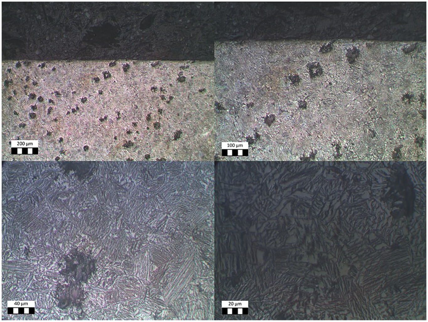
ADI 1000 structure, showing nodular graphite and austoferrite acicular structure.
ADI mechanical properties are superior to pearlite ductile castings, and this fact makes them interesting for high-commitment parts (for instance, moving parts in heavy-duty equipment and other critical components). ADI ultimate strength value ranges from 900 to 1400 MPa. Some examples of use can be found1–3 in agricultural equipment, construction machines, gears, 1 heavy trucks and trailers, buses, luxury cars, mine equipment, 2 railroads, and power generation systems. The use of ADI is making its way into new markets, particularly the growing sector of renewable energy in wind power generators. Thus, in windmills gearboxes, weight is a severe construction drawback 4 and ADI allows to decrease it.
In order to obtain ADI castings, 3 heat treatment must be applied, shown in Figure 2; the evolution diagram shows the relation between temperature and time along with the heat treatment phases. So, the treatment first phase consists of austenitization; thus, the soft iron casting parts are heated up to 900°C to reach the austenitic region (AB) where parts are maintained at that temperature around two hours (BC). During this time, austenite is enriched with carbon and some graphite is dissolved inside austenite. Hence, austenizing conditions are influenced not only by (a) temperature but also by (b) time, (c) piece cross-section and thickness, and (d) the number of graphite nodules imbibed in the cast. Therefore, austenizing time should be the minimum required to heat the whole part to that temperature and so saturate austenite in balance with the level of carbon.
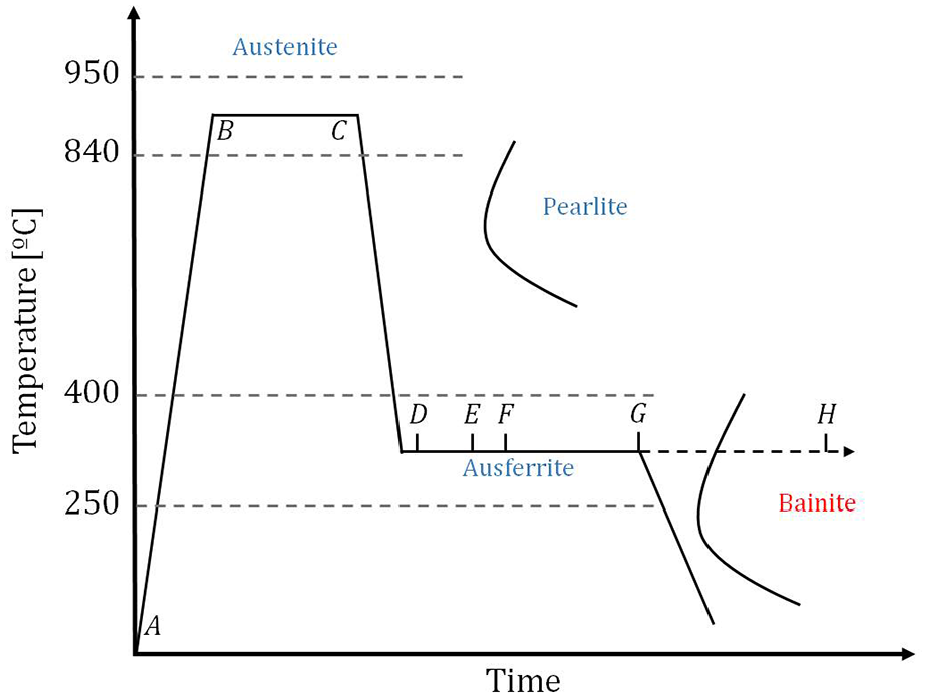
ADI phases diagram (Temperature-time).
The second phase is called austemperization. At this stage, an isothermal transformation (DE) happened after the quick cooling (CD). In a salt furnace equipment, pieces are maintained between 240° and 390° for 1.5 h. Some austenite amount is transformed in needles of ferrite separated by austenite till the two-phase equilibrium. So, carbon expelled from ferrite is absorbed by austenite without the risk of appearing martensite. Grades around 800 MPa strength are produced applying 380°, whereas at low temperature level higher strength and less ductile grades are produced. The stage time is critical to avoid the starting and growth of undesired perlite or bainite. For comparison, in the steel case, the treatment usually leads to bainite, a weak phase regarding its mechanical properties.
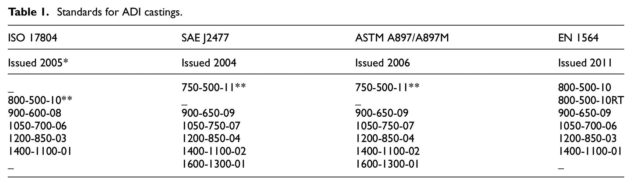
ADI family includes several grades with different mechanical properties and enormous differences regarding machinability.5–9 ADI standards are gathered in Table 1, being ADI 900 and 1000 the most demanded by the industry. Figure 3 compares ADI strength and ductility with other Fe-C steels and casting.
Standards for ADI castings.
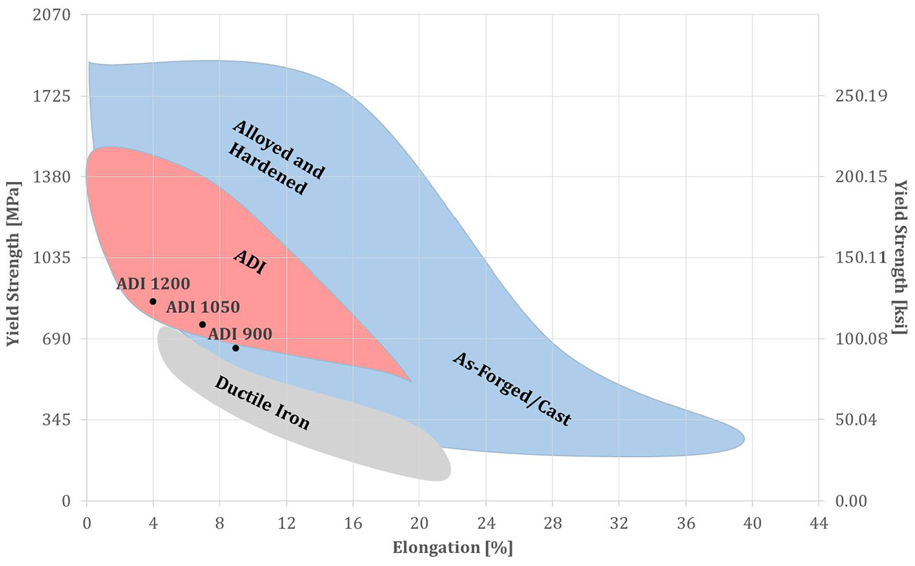
ADI casting related with other Fe-C alloys and castings. Points are referred to minimum mechanical values accepted by standards.
Thus, Cemal et al. 3 studied carbide performance in turning, as it was also done by Seker and Hasirci. 10 Crater wear mechanism dominates tool life when using carbide inserts. This type of wear appears near cutting edges, implying a high risk of tool breakage. Besides, ausferrite microstructure can cause adhesion on tungsten carbide tools, causing micro-welding effects that accelerate tool wear. Another consequence of ADI high hardness is tool abrasive wear.
Because of ADI low machinability, to perform as many operations as possible before heat treatment is recommended. This approach is applicable, especially for roughing and operations with low-dimensional geometry requirements. However, it is not possible to apply when tight design tolerances are required because heat treatment implies severe part distortion. In this case, semi-finishing and finishing operations must be performed after heat treatment with the material at its maximum strength and hardness.
This work is focused on turning, in which ceramic tools are a radical solution to improve productivity. 11 The so-called “technical ceramics” are very hard and resistant to high temperatures. A clear drawback is the ceramics low toughness. Another disadvantage is their cost regarding carbide inserts, but this aspect is mitigated by the high-performance cutting applying very productive machining conditions.9,12
Since 1960s there was continuous improvement of technical ceramics, Si3Ni4, Al2O3 and ceramic composites; however, the first patent about alumina dated from 1912 and 1913 in UK and Germany respectively. In the 60s, alumina was reinforced with 45 vol% SiC whiskers. Typically, whiskers contain β or a mixture of α and β phases of SiC, dimensions ranging from 0.05 μm to 1.0 μm in diameter and 5 μm to 125 μm in length. The reinforcement brings up a fracture toughness (MPa·m1/2) raise from 3.3 ± 0.2 to 4.6 ± 0.2 at 1500°C. The toughening of ceramics by particle dispersion was first studied in the 1960s. So, the so-called “mixed ceramics” include Al2O3 matrix grains with nano TiC particles. Dislocations inside the matrix grains can also increase flaw tolerance (micro damages), resulting in a tougher composite. This ceramic has both high-hot hardness and low plasticity, and commonly supported by dry lubri-cooling techniques.13,14 In addition, the ceramic dark gray color leads to be so-called black ceramics. On the other hand, in 1970s new ideas about substituting silicon and nitrogen in the Si3N4 structures led to Siz-6AlzOzN8-z solid solution so-called SiAlON. So, they are solid solutions of silicon nitride in which Si–N bonds are partly replaced with Al–N and Al–O bonds. SiAlONs have enhanced wear resistance, low thermal expansion, and excellent oxidation resistance above ∼1000 °C.
On the other hand, the preparation of ceramic cutting edges was studied by several authors for carbide tools15–17 before and after coating, and in ceramics18–19 as well, showing a significant influence on tool life.
In the work here presented, the main aspects of achieving high performance of ceramics in turning area approached and analyzed, following as two-stage testing procedure, as stated by Fernandez et al. 20
Experimental testing
The multitasking turning center used for machining tests was CMZ© (TC25BTY), a turning center with an integral spindle power of 35 kW and rotational speed up to 4000 rpm, commanded by a NC Fanuc© control (type 31iT LVH). The integral spindle is essential to assess machining test rigidity and to eliminate turning vibrations.
Test piece material was ADI 1000, in form of rod with the following dimensions: ∅150 mm and L400 mm. ADI 1000 is designed as EN-GJS-1000-5, presenting ultimate tensile strength of 1000 MPa and yield strength of 700 MPa. Material composition determined in wt.% was: 3.56% C, 2.18% Si, 0.22% Mn, 0.021% P, 0.007% S, 0.063% Mg, 0.76%Cu, 1.9% Ni, 0.24%, Mo, and the balance iron. This grade was selected due to the growing industrial interest on it, because it is the next evolution after using ductile irons with a maximum strength of 700 MPa. To reach ultimate strength of 1000 MPa, all the specimens were subjected to heat treatment consisting of two phases described in Section 1: an austenitization at 900°C and austempering in a molten salt furnace at 390°C. To analyse ADI homogeneity, several cutups were performed, some shown in Figure 1 with no significant variations.
The following subsections describe research steps carried out; the first one was aimed at obtaining the specific cutting force value, the second one to analyse the performance of the ceramic inserts in ADI. And the last one to define the optimal ceramic inserts application parameters.
Specific cutting force
The first step consisted of determining the specific cutting force value of ADI 1000. For this purpose, a hard metal (or sintered carbide) tool was selected, commonly used for any kind of machining, CNMG120408 type without chip breaker.
For cutting force acquisition, Kistler® dynamometer (model 9257B©) was mounted on lathe turret, as shown in Figure 4. A multichannel signal amplifier type 5017 and a data acquisition (OROS® NV GATE 6.2) software were necessary to record force signals. Then, signals were processed and filtered to obtain stationary values. Regarding cutting force component axes and machine-tool ones, the correspondence is as follows: cutting force along cutting speed direction Ft is lathe Y-axis, cutting force along feed movement Ff is Z-axis, and finally, binormal force component along the depth of cut direction Fb is X-axis, the operation was the cylindrical type.
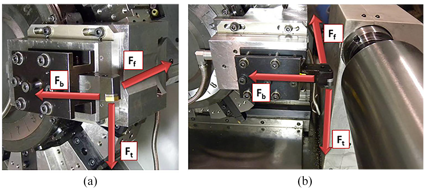
Measurement dynamometer axes: (a) dynamometer and (b) position respect to test piece. Ft is the lathe Y-axis, Ff is Z-axis, Fb is X-axis.
The methodology defined to obtain the specific cutting force defined semifinishing and finishing typical values performing a combination of cutting conditions for different values of depth of cut (a [mm] = 1.5 and 0.5), feed (f [mm/r] = 0.2, 0.3, 0.4 and 0.5) and cutting speed (vc [m/min] = 90, 100, 110, 120, 130 and 150).
New cutting inserts were used during tests at 1.5 mm of the depth of cut, covering all defined cutting speeds for each feed. At the same time, cutting forces during turning were measured thrice, ensuring the correct recording of the data. For the finishing stage, the measurement process was similar to semifinishing, but the depth of cut was defined as 0.5 mm. New inserts were used in each test to eliminate any effects on cutting force coming from wear.
At the view of the results about cutting force measurements for different cutting conditions, Figure 5 shows the relation between cutting forces and cutting speed for a = 0.5 and 1.5 mm and f = 0.4 mm/r.
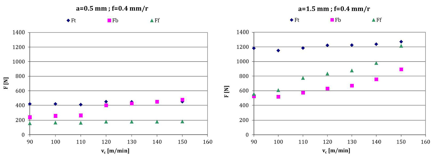
Experimental cutting forces for a = 0.5 mm and 1.5 mm, and f = 0.4 mm/r, along different vc values (average of three values).
All the selected cutting parameters showed the same tendency. Thus, tangential force (Ft) is not conditioned by cutting speed so that it could be defined as a constant value. Meanwhile, the binormal (Fb) o radial force and feed force (F f ) are more influenced by cutting speed values, being significant over values of 120 m/min. Finally, the feed force (Ff) presented a considerable variation with the depth of cut, being almost constant using a = 0.5 mm. Nevertheless, when the depth of cut was higher than 1.5 mm, while the chip section increased the feed force component value increased. The lack of relation of cutting speed with tangential force is common if speeds do not dramatically increase. And regarding the second trend, feed and depth of cut are related one with each other at high values.
Thus, the specific cutting force components along the three force main directions were obtained. Figure 6 shows cutting force components values depending on chip thickness. The increment at low chip section values (a*f) is the usually so-called size-effect. It is explained because at small chip sections, the division of cutting force that is a sum of the shearing (related to chip section) and friction or rubbing (independent) effects by chip section includes a mathematical aberration. 21
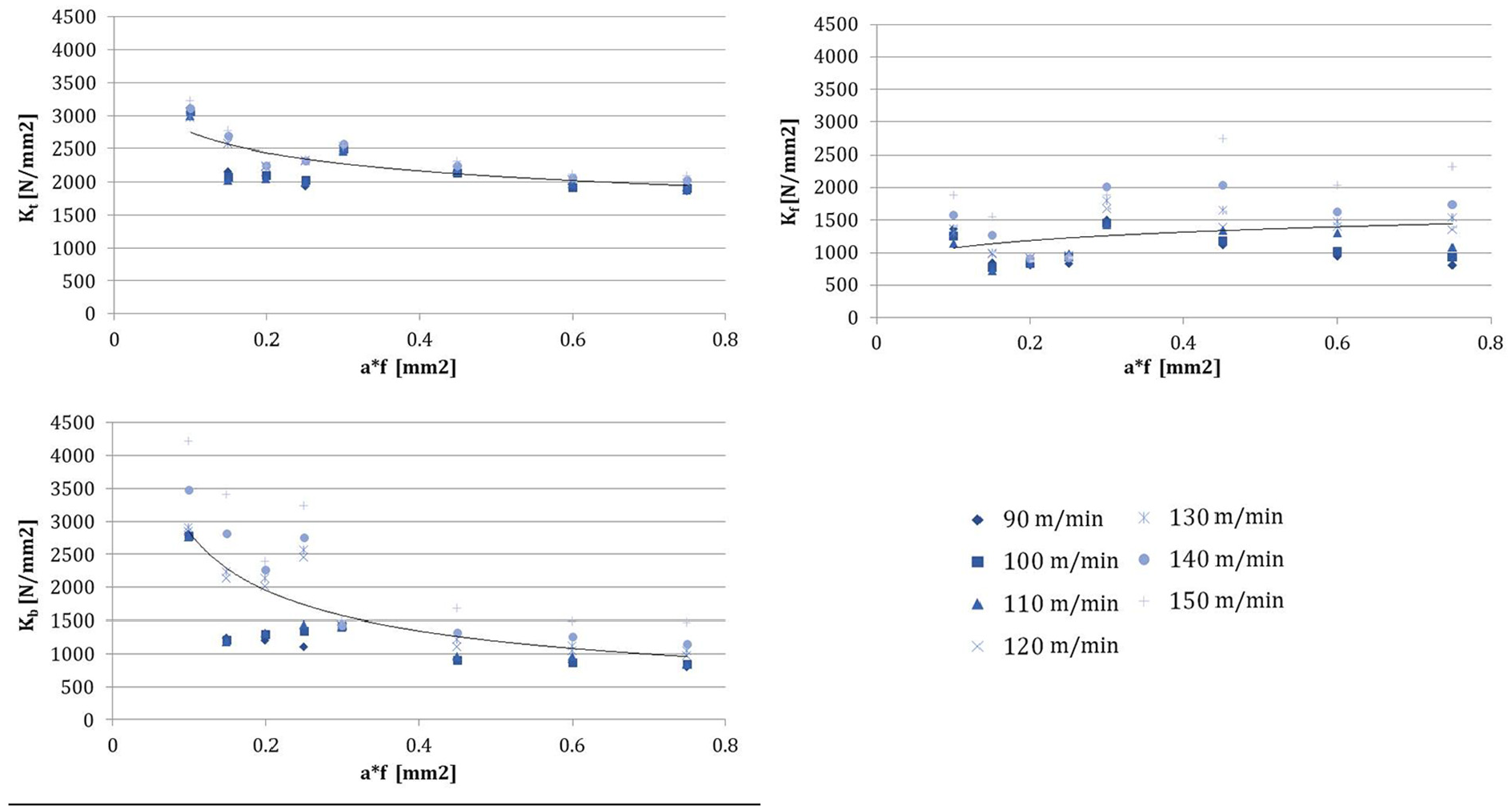
Specific cutting forces in the three axes.
It should be highlighted that value found out for the specific cutting force in the tangential component (Kt) for ADI 1000 was around 2000 N/mm2. The value can be comparable to steels of similar mechanical characteristics, and it is higher than ductile castings.
Ceramic inserts testing
Inside the ceramic cutting tools family, five types are distinguished:
Ceramics based on aluminum oxide (Al2O3), chemically stable but sensitive to thermal changes.
Mixed ceramics (alumina with TiC), TiC added carbides improve both toughness and thermal conductivity.
Another way to increase the toughness of ceramic inserts is using SiC carbide filaments (whiskers, 25% vol. approx.). This type of ceramics (SiCW) presents a good behavior even using coolants, and in milling that is an interrupted cutting process.
Finally, silicon nitride (Si3N4) ceramics are mainly used in machining of gray castings. In this fourth case, SiAlON ceramics provide better chemical stability than silicon nitride inserts for similar resistance properties. Thus SiALON is another family.
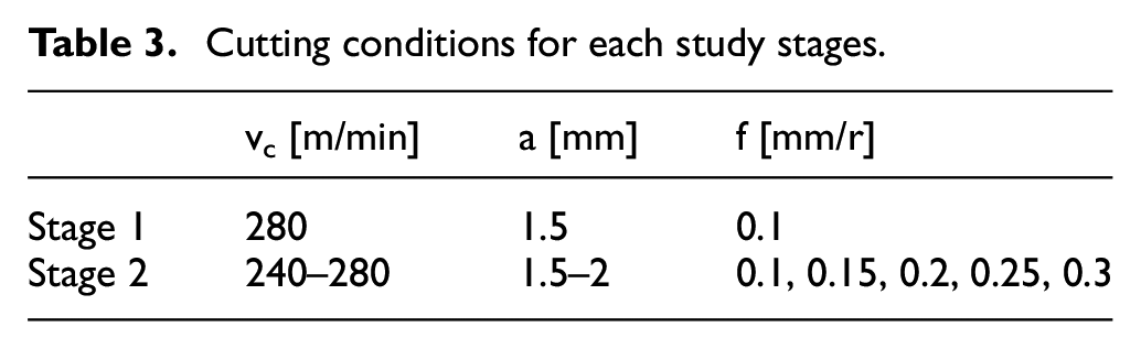
Regarding insert type, a standard round geometry button type (RNGN 120700) was selected. According to ISO designation, these are round inserts diameter 12.7 mm, neutral themselves with relief flank angle of α = 0°. Differences between the proposed inserts laid in the ceramic grades and edge preparation. The toolholder reference was CRSNR M12-ID 2525. From the combination of these two elements, insert and toolholder shown in Figure 7, the final spatial positioning was clearance angle α 6°. Ceramic inserts are neutral, so rake angles (primary and secondary) were γ–6°, that implies negative rake angle. Table 3 shows data for the ceramic inserts studied.
Cutting conditions for each study stages.
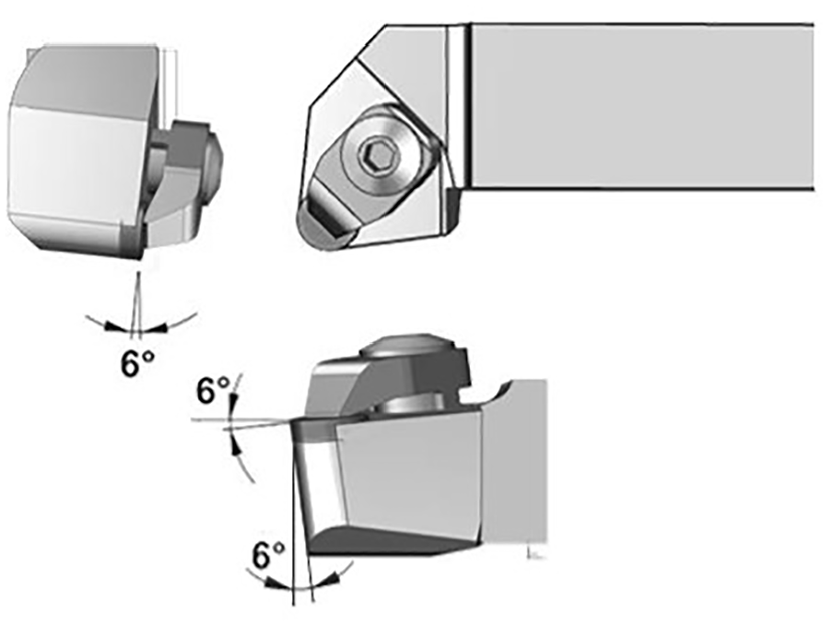
Geometry of toolholder-and round insert.
On the other hand, the effect of cutting-edge geometry, also known as “edge preparation,” on machining is receiving attention in recent years due to the expansion of new turning techniques. Two approaches are hard turning and micromachining, both using PCBN (Polycrystalline Cubic Boron Nitride) 6 and ceramic tools. In reference, 6 it was observed that cutting edge microgeometry is strongly related to cutting force, chip formation and tool wear and life. In order to eliminate problems such as edge chipping or cracking, and breakage during machining, tool manufacturers continuously modify cutting edge geometry, being (i) chamfering or (ii) a combination of chamfering with rounding the most common ones.15,16
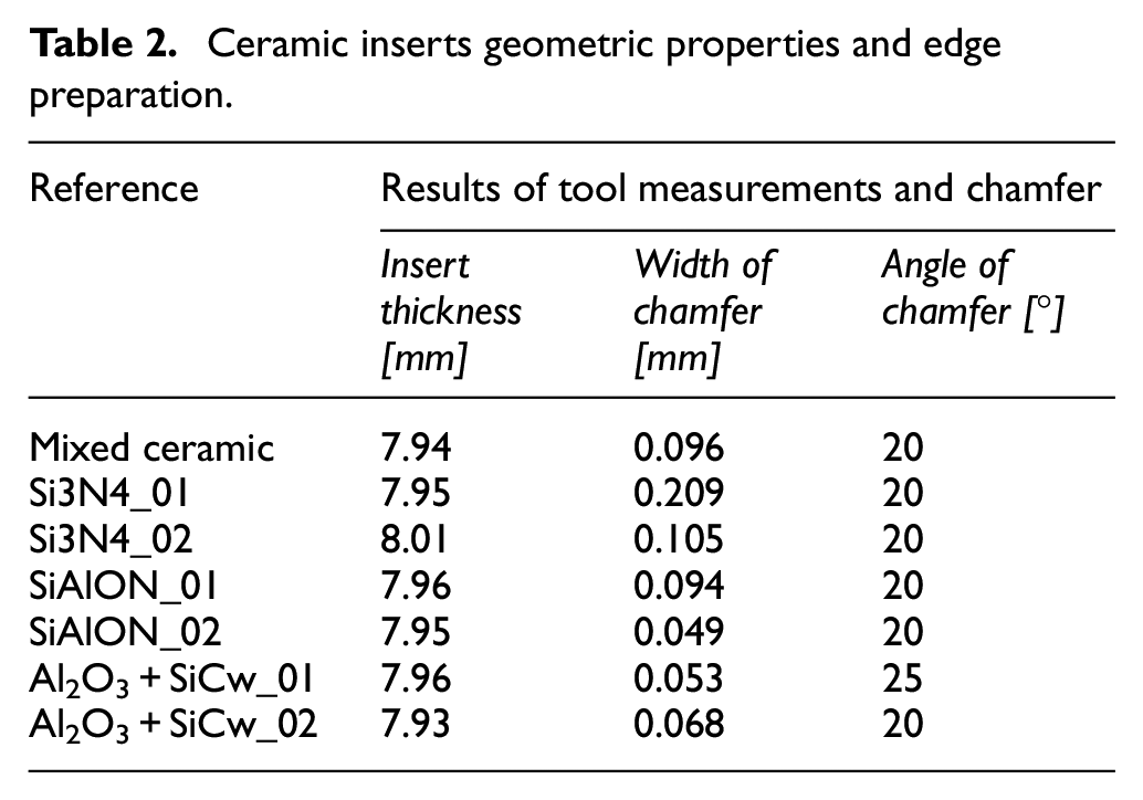
One of the key points for ceramic tool successful use is the specific edge preparation for each work material and operation. 19 In our testing, Figure 8 shows the width, angle of chamfer, and nose radius characterized. For the measurement of cutting edges a confocal microscope Leica® 3D DCM was used; one result is shown in Figure 8. Edge measurements were accepted if more than 96% of the points were successfully measured. Table 2 presents the chamfer values of selected ceramic inserts. Chamfer angle was 20° at approximately all inserts except for the Al2O3+ SiCw_01 reference, which was 25°. Regarding the width of chamfer, three groups were distinguished with values of 0.2, 0.1 and 0.05 mm (those values around 0.05 can be considered rounded shapes, more than chamfers).
Ceramic inserts geometric properties and edge preparation.
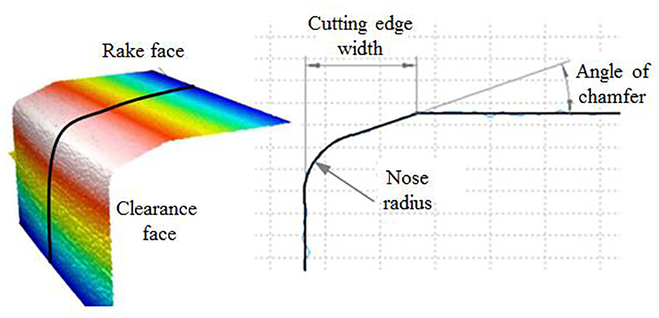
Edge preparation: main geometric features.
In a practical order, wear measurement in round ceramic inserts imply releasing each insert for inspection and then replace it onto toolholder, which is long and arduous. This difficulty was solved by performing measurements using a digital microscope mounted inside lathe, checking wear at each tool pass. Finally, once each test was finished after several passes, each insert was inspected using a Mitutoyo magnifier © Model TM-500 for final analysis.
Ceramics experimental testing
The proposed work was divided into two experimental campaigns following the methodology defined by Fernandez et al. 20 Turning tests were designed to study tool wear suffered by different types of inserts, evaluating wear patterns for various cutting conditions (on example is supplementary video to this paper). Thus, Table 3 summarizes the cutting conditions used in the two-stages experimental testing with ceramics.
During the first stage, many inserts suitable to withstand turning operation were identified in the market, those that can maintain low wear without tool catastrophic failure. At this campaign, some inserts were discarded. Then, short-time tests were performed in order to estimate wear rate. This testing gave a general preview of inserts behavior, and allow to select the most suitable ones.
At the second stage, different cutting conditions were programmed to evaluate the effect of various parameters on tool wear, using the inserts successful from the previous campaign.
Experimental results
First stage: Identification of wear patterns
Different tests were performed under the same turning conditions with different types of technical ceramics, presented in Table 2. So, regarding tool wear pattern, Table 4 first column shows ceramic cutting edges just after cutting. And in the second column, cutting edges are shown once built-up edge was removed.
Tool wear patterns: After testing and with adhesion layer removed.
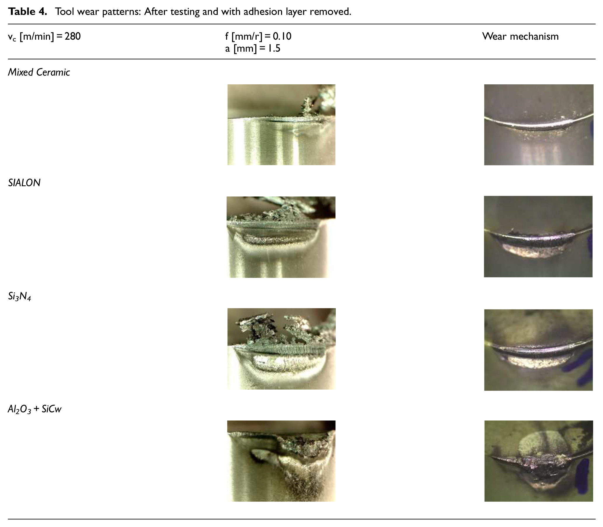
After images analysis, the adhesion of ADI onto inserts rake surface near the cutting edge was quite common. Thus, Si3N4 ceramics severely accused this effect since ADI adhesion was all along the entire length of the engaged cutting edge. In contrast, mixed ceramic inserts were less prone to suffer this wear type, leading to built-up ADI only in zones remarkably close to cutting edges, and in those cases working at higher cutting speed.
For the proposed machining conditions, except in (Al2O3+ SiCW) tools, flank wear was quite uniform. For inserts (Al2O3+ SiCW), a rapid notch wear growth in flank faces was observed, implying a high risk of tool edge breakage. Because of this wear type, it was decided not to continue with this type of ceramics in the following experimental phases. On the other hand, this kind of ceramic is the most expensive, and more used in milling than in turning.
Finally, flank faces abrasion was the primary wear mechanism, with a low value for mixed ceramics. Additionally, crater wear was located on inserts rake face; and a heat-affected zone (HAZ) also appeared onto tool flank faces. Mixed ceramic presented the lowest wear. Moreover, using more severe cutting conditions, notch wear was appreciated.
Wear rate estimation
As is well-known, tool wear is an essential factor in machining costs. This influence led to a variety of evaluation methods21–24 to identify those tools with the best performance. Some machinists use force vs. machining time plots, here the slope of the curve representing the increase in machining force. In this way, Figure 9 shows the cutting force evolution along machining time for ceramic inserts. As shown, binormal (Fb) and feed force (Ff) components are not too significant; tool wear depends on the force component along cutting speed direction. Due to this, tangential force (Ft) was the key component to identify the wear rate for each of the tools. Moreover, tangential cutting force components at the initial time were quite similar for all ceramics. However, the longer the time, the higher the tangential force difference, so it can be used to estimate the wear rate.
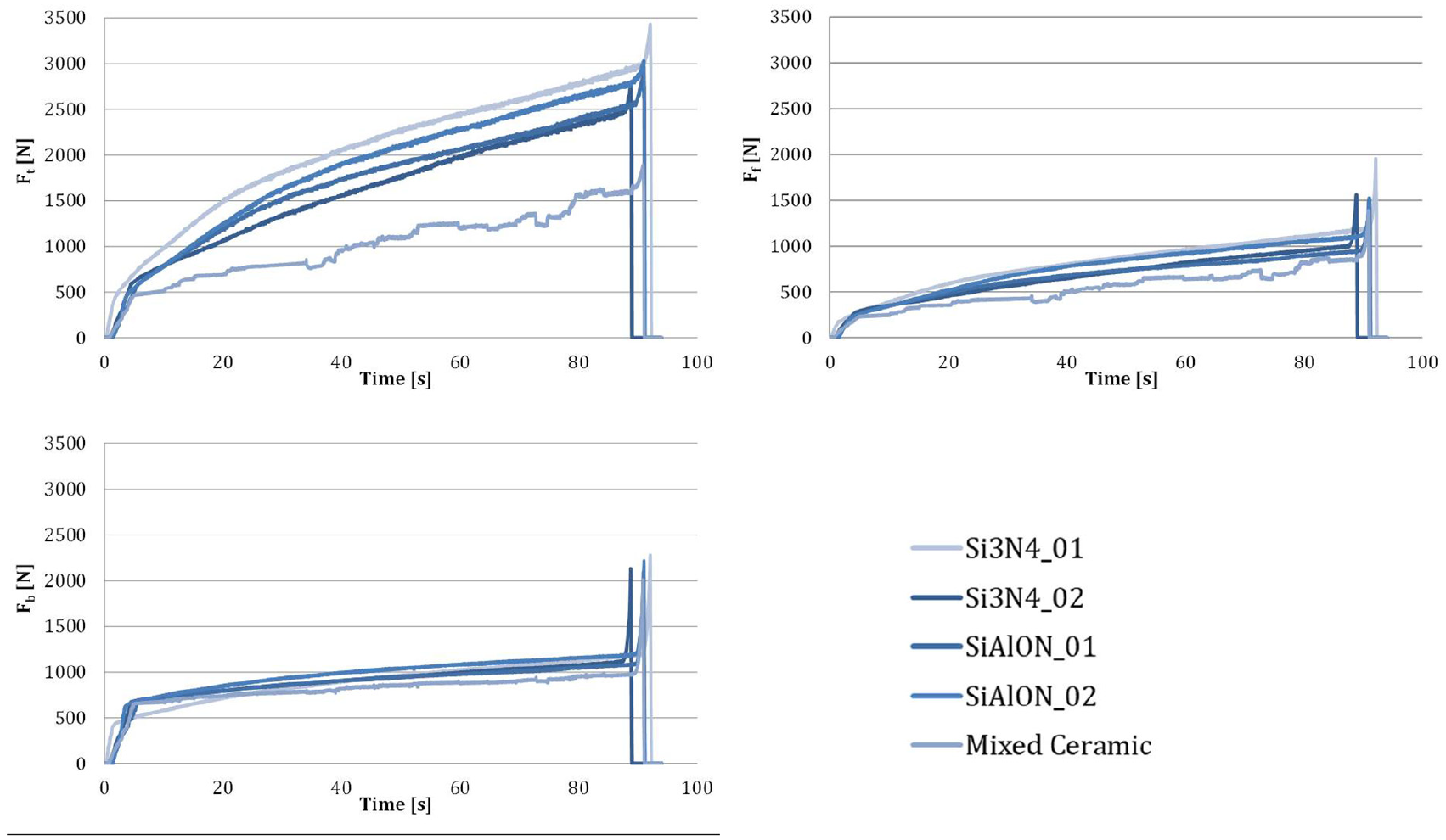
Cutting force components versus machining time.
Figure 9 shows slopes for the three force components. Mixed insert ceramic presented the lowest slope, very significantly. Thus, fixing a wear limit for all the inserts, mixed ceramics could remove higher chip volume. Tangential force evolution can be an indicator of ceramic wear. Figure 10 shows the velocity of the force variation for each ceramic insert, being Ft the significative one.
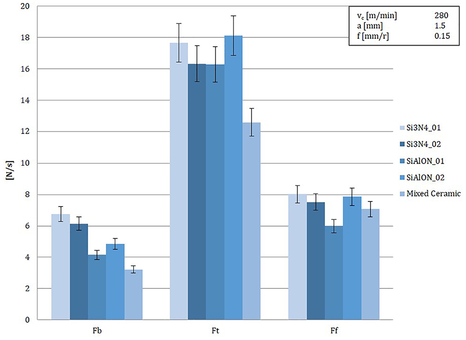
Estimation of wear rate.
On the other hand, the efficiency of Si3N4 ceramics can be due to two factors. First, inserts are produced by different manufacturers, so even though its composition is mainly based on Si3N4 some differences can be expected between them. Second, some differences were detected in cutting edge geometry (edge preparation). So, the ceramic reference with the smallest width of chamfer (0.1 mm) provided the best performance. The results from SiAlON presented some differences, even though the same manufacturer provided the two insert types, and the composition was the same. The only difference between the two was cutting-edge geometry. Again, the best performance was observed for the insert with the width of chamfer 0.1 mm, the same preparation as in the case of mixed ceramics and Si3N4.
Second stage: Influence of turning cutting parameters
The second researching stage was focused on the performance of mixed ceramic inserts, which was selected because it was the best choice from the previous steps. The initial conditions of vc 240 m/min and ap 1.5 mm were increased by 15% (up to 280 m/min) and 30% (2 mm), respectively. In all three cases, five feed rates were tested from 0.1 to 0.3 mm/r in steps of 0.05, as shown in Table 1.
Figure 11 shows the evolution of the tangential force along machining time for different cutting conditions. This force component is the most representative of tool wear. Thus, the increase of the feed per revolution induces an increase in the shear stress due to larger chip sections. Because abrasive wear is the dominant mechanism, as the stress level increases the wear rate does too, increasing exponentially for feed values higher than 0.25 mm/r. For the same reason, increasing the depth of cut has more influence on wear rate than increasing cutting speed.
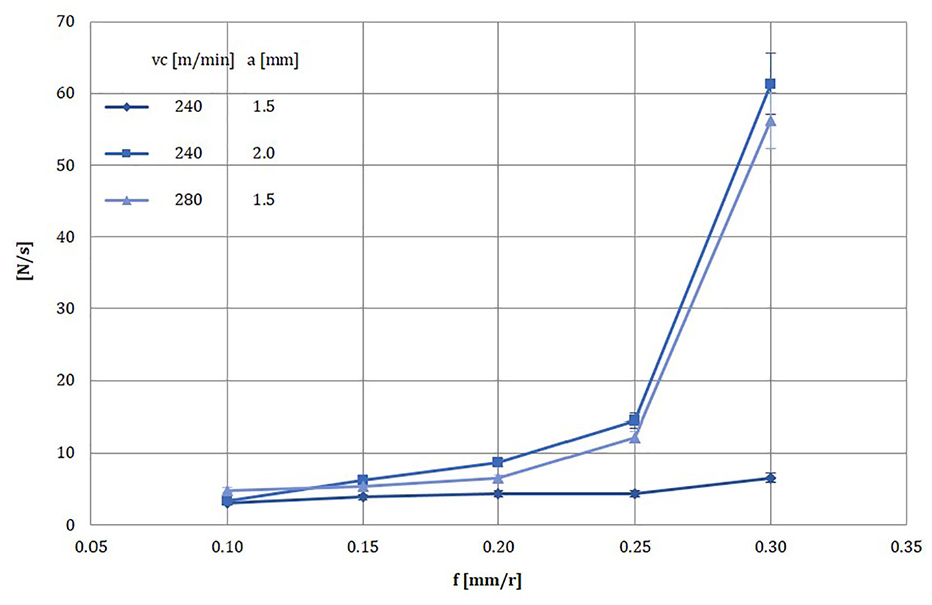
Effect of the cutting parameters on Mixed ceramics tool wear velocity.
After being repeated three times all the tests, a conclusion is that cutting force variation velocity at higher cutting speed is sensitive with feed per revolution, meanwhile at a moderate value of 240 m/min is near-constant. In conclusion, the increase in measured cutting force aims indirectly at tool wear; this can be useful in automatic surveillance systems in workshops.
Conclusions
The lower ratio between weight and ultimate strength is the main reason to select ADI castings in multiple machines and equipment components. However, material machinability is lower than ductile iron casting.
The feasibility of using ceramic inserts in dry turning of casting ADI 1000 (EN-GJS-1000-5) has been evaluated. Several conclusions can be pointed out:
Wear mechanisms and patterns using mixed ceramics, Si3N4, and Al2O3+ SiCw and SiAlON were studied. It was observed notch wear for SiAlON that implies a rapid edge chipping. Nevertheless, the other ceramic inserts presented built-up on cutting edges as the dominant wear mechanism. This type of tool wear presents a less unexpected breakage risk.
Mixed ceramics presented better abrasive tool wear resistance. Additionally, the insert edge design (edge preparation) of chamfering 20° and 0.1 mm chamfer width obtained the optimal tool performance.
Feed values over 0.25 mm led to a rapid increase in wear velocity, which implies a maximum feed value to work under optimal cutting conditions in ADI.
On the other hand, depth of cut and cutting speed were analyzed; depth of cut has a more significant effect on tool wear than cutting speed. Thus, wear evolution is strongly determined by chip size while cutting speed is not considered crucial; this is a big difference with steels of the same ultimate strength. A conclusion is that ADI casting, even with a strength similar to steels, is still a casting; casting implies lower deformation energy at chip formation, and therefore the cutting zone temperature is not strongly dominated by cutting speed.
So, mixed type ceramic insert provides the best performance when turning ADI 100 casting.
Footnotes
Acknowledgements
Authors are grateful to Basque government group IT IT1337-19 and the Ministry of Mineco REF DPI2016-74845-R and PID2019-109340RB-I00. Thanks are addressed to all people staying patiently at home in this virus crisis, and to medicine people taking care of other people and fighting COVID 19.
Declaration of conflicting interests
The author(s) declared no potential conflicts of interest with respect to the research, authorship, and/or publication of this article.
Funding
The author(s) received no financial support for the research, authorship, and/or publication of this article.
Supplemental material
Supplemental material for this article is available online.