
Abstract
Gear roll forming process is an innovative near-net-shape gear manufacturing technology for efficient manufacturing, high material utilization rate, high products strength, and outstanding surface quality. The profile of the Tooth of the Rolling Tool (TRT) has a direct impact on its strength/stiffness which further affects its life duration and the accuracy of the formed products. Research has been carried out to design the involute curve of TRT, however, the transaction curve of TRT which also has a significant impact on tooth strength and service durability remains to be designed and optimized in order to further improve the rolling performance. In this paper, an elliptical gear tooth root transaction curve is proposed to replace the traditional fillet curve for the enhancement of tooth bending performance. The maximum root stress and stiffness of the gear tooth with elliptical transaction curve are calculated and compared to the standard profile with different parameters (modulus, pressure angle, and coefficient of bottom clearance). The results show that proposed elliptical tooth reduces the maximum root stress and increase the strength and stiffness of TRT especially significant for rolling tools with small number of teeth and coefficient of bottom clearance.
Introduction
Gear roll-forming process has received much attention in recent years due to its advantage on high material utilization rate, high products strength, and outstanding surface quality.1–3 This new gear manufacturing technique combines both the advantages forging and rolling, therefore, the formed products generally have better anti-fatigue performance compared to the normal gears manufactured by cutting process. The contact force between rolling tools and workpiece during the forming process leads to large tooth bending deformation or even tooth breakage, which decreases the products’ forming accuracy as well as the life duration of rolling tools. Profile design of the Tooth of the Rolling Tool (TRT), process parameter control, and rolling method are generally utilized to improve the gear roll-forming performance. Neugebauer et al.2–4 designed an alternative pitch die and speed controlled force synchronization system according to forming feature and variable pitch, and then analyzed the parameters and forming equality roughly. This presented method shows up to a 50% improvement in pitch accuracy and the ability to roll high teeth gears. Kamouneh et al. 5 has used FEM to verify and quantify the improvements obtained from reverse rolling of gears and presented possible solutions to three gear flatrolling problems; Rabbit-ear, asymmetrical flanks, and barreling. Khodaee 6 applied a specific axis-feed and rotational speed to form the standard involute on the workpiece and evaluated the shape accuracy with a modulus of 1 mm and 4 mm. It is shown that rolling of gear wheels with large module will produce more deviations and result in lower qualities in general. Sieczkarek et al. 7 provide an analytical model for the incremental forming of gears along the direction perpendicular to the sheet thickness and results show that the indentation force can be significantly reduced by stress superposition. Ma et al. 8 proposed an analytical model for calculating the pitch error with consideration of workpiece dimension and process parameters in the initial stage of gear roll-forming, which leads theoretical foundation for reducing the pitch error in the gear roll-forming process. Fu et al. 9 developed a simplified finite element (FE) model coupling electromagnetic-thermal and deformation fields and validated the model by corresponding experiments to investigate the gear forming process. The formability is improved by using local induction heating and the rolling force drops drastically compared with cold rolling process.
In addition to rolling process parameter control, profile design and modification are considered to be promising approaches to reduce the deformation of TRT. Yu et al. 10 selected upper part of standard involute gear as the profile of rolling tools to wedge in workpiece simpler. Wu et al.11,12 proposed the conical design rolling tools and conducted the experimental comparison by rolling tools with different conical angles, revealed that the proposed design achieves better uniform tooth graduation and refining of the tooth profile. Ma et al.13,14 divided rolling tools into three sections: entrance section, correction section, and exit section. The results shows that the optimized geometric design of rolling tool will not only reduce the deflection and root stress of rolling tool’s teeth, but also eliminates the scratches on tooth flank of the formed gear.
The previous researches on gear rolling tools mainly focused on structure design to reduce the forming forces, however, the strength of the gear teeth on rolling tool is weak, which leads to large deformation during the rolling process and thus reduces the forming accuracy of the workpiece. This paper proposes a novel profile design of the TRT to reduce the root stress and enhance its tooth stiffness. This paper is organized as follows: Section “The geometry of the proposed gear tooth profile” presents the proposed design approach and calculates the parameters of elliptical transaction profile of TRT. Section “The mathematical model” explains the calculation method for stiffness and maximum root stress of TRT. Section “The comparison of the maximum root stress” and section “The impact factors on the stiffness of rolling tool” compare the maximum root stress and stiffness of standard and optimized profile of TRT with different parameters, respectively. Section “Conclusion” concludes this paper.
The geometry of the proposed geartooth profile
The structure of the gear rolling system with axial-infeed developed by SKLMT at Chongqing University is shown in Figure 1. Two rolling tools have the same rotational speed controlled by motors and transmission system, which consists of belt pulleys and worm gears. The racial-infeed cylinder adjusts the center distance according to different workpiece. The workpiece are pushed through the space between two rolling gears by axial-infeed cylinder and the workpiece is deformed into a gear with involute teeth through the meshing with rolling gears.
Illustration of the gear rolling system at SKLMT. 10
The standard gear profile and optimized elliptical curve are shown in Figure 2. The definition of all symbols is shown in the Table 1. A coordinate system is established on the gear center. The center of designed elliptical curve is noted as C1 and C1 is located on the symmetry axis. a and b are radii of the elliptical curve on the semi-major axis and semi-minor axis respectively. d is noted as the distance between the center of elliptical curve and pitch circle. Assumed point M is on the elliptical curve, the parametric equation of the circular fillet can be expressed by function of θ1:
Comparison of standard transition curve and elliptical curve.
Notation.
The pitch radius is denoted as r1 and the pressure angle on the pitch circle is 20°. θ1 is the ellipse parameter and the range of value is [θ1min, π-θ1min] with:

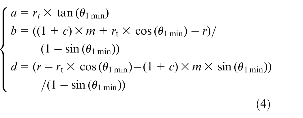
The ellipse is tangent to tooth flank and root surface, the radii a, b, d can be evaluated by:
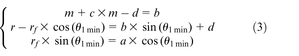
Based on equation (3), one can obtain
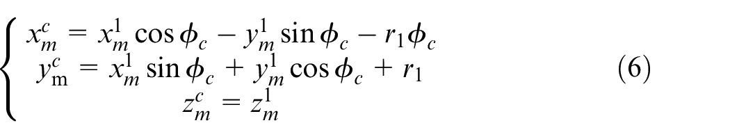
The geometry of the gear rack-cutter is related to the proposed tooth profile. The coordinate transformation from the proposed gear to rack-cutter is shown in Figure 3. Coordinate systems
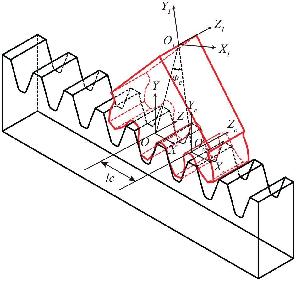
The coordinate transform between the rolling tools and rack-cutter.
The conjugate rack surface can be obtained by coordinate transformation based on the concept of the envelope.
The family of surfaces
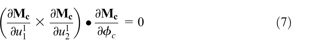
equation (7) can expand as:
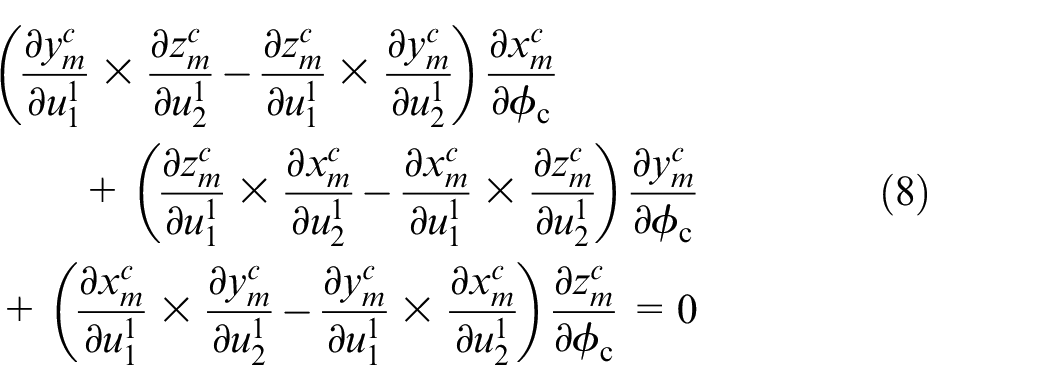
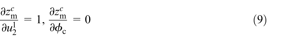
Substitute equation (9) into equation (8), equation (8) can be simplified as:
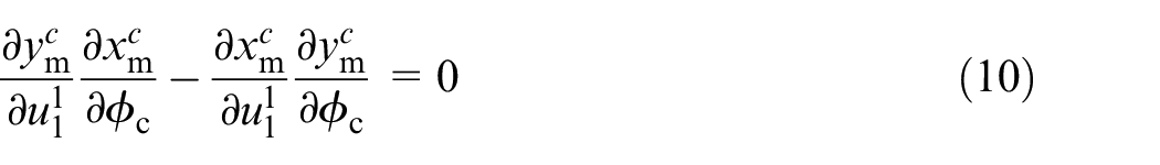
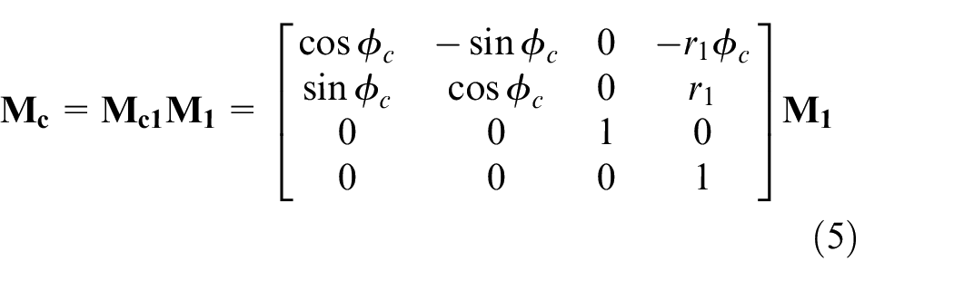
Substitute equation (6) into equation (10) and simplify it to obtain the equation of Φc. equation (10) can be rewritten as:
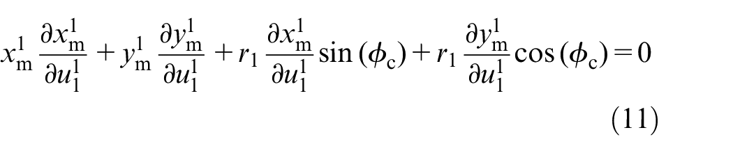
Substituting equation (11) into equation (6), the family of surfaces Mc (
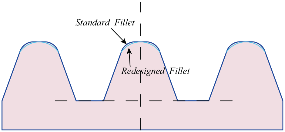
The comparison of standard fillet and optimized fillet on gear rack.
The mathematical model
The calculation of root stress
The maximum stress is calculated for different number of tooth and coefficient of bottom clearance. The calculation procedure of maximum root stress is shown in Figure 5. The maximum root stress of the TRT is studied by assuming a normal load at the Highest Point of Single Tooth Contact (HPSTC). The location of the HPSTC is calculated as the joint point between single tooth-meshing and double tooth-meshing. The single tooth-meshing section and the double tooth-meshing section in an engagement period are shown in Figure 6.
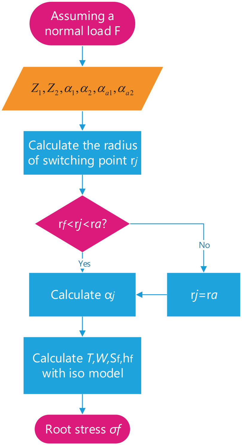
Calculation procedure of maximum root stress.
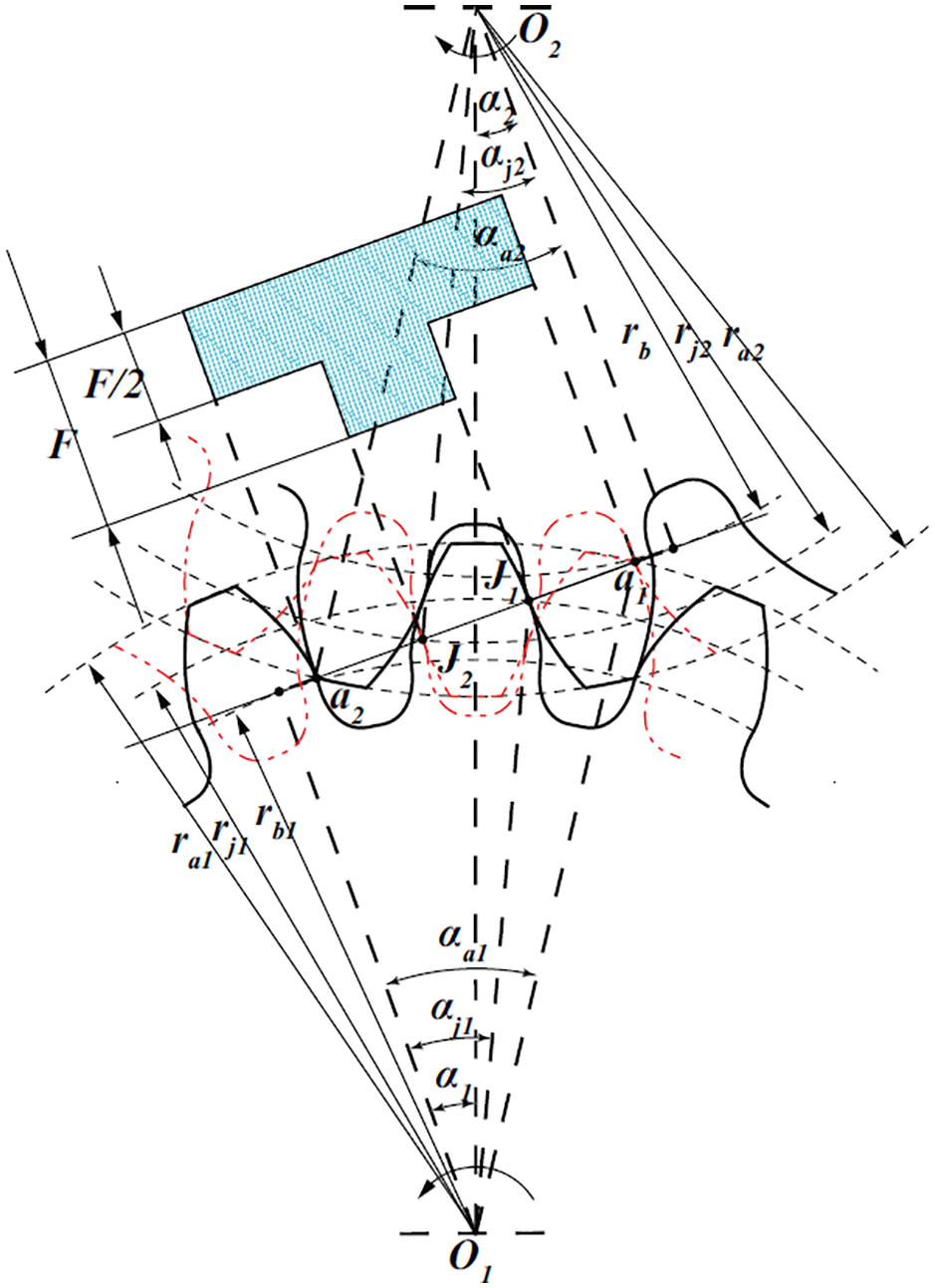
The tooth engagement period.
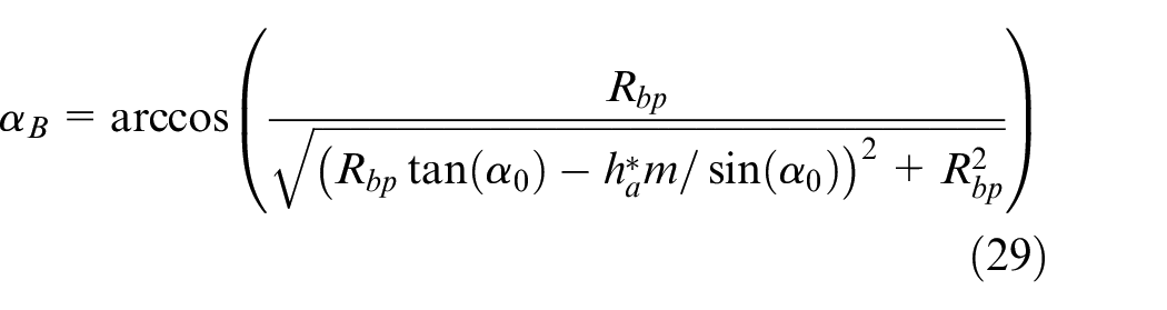
The pressure angle on pitch circle, addendum circle of Gear 1 and addendum circle of Gear 2 are noted as
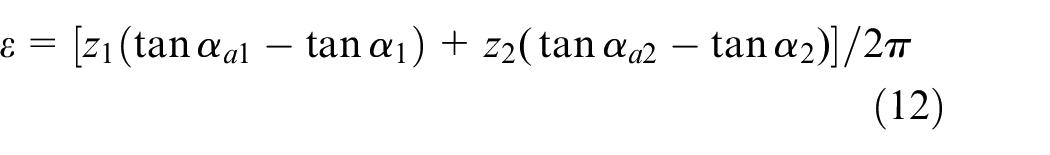
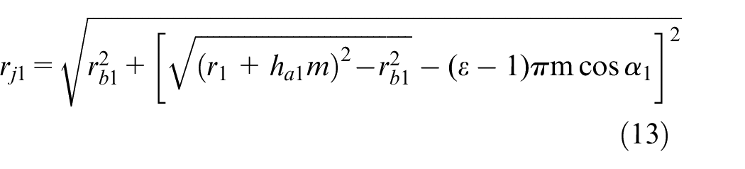
The radius of the switching point between the single teeth-meshing area and the double teeth-meshing area can be calculated by:
The pressure angle on this point can be obtained by:

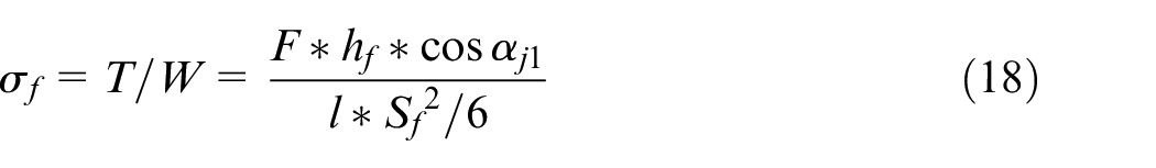
The most common mathematic model to calculate the maximum tooth root stress is 30° incline tangent method recommended by ISO, 15 which is shown in Figure 7. The inscribed profiles are oblique line 30° from the vertical line. Critical section location is determined as the tangent point of the gear profile and inscribed profile. The distance between two tangent point is defined as Sf. The vertical distance between the stress point on the symmetry axis and tangent point is noted as hf. The force loaded on the switching point between single tooth engagement and double tooth engagement is noted as F. The maximum bending moment can be calculated as:

where β can be obtained by:

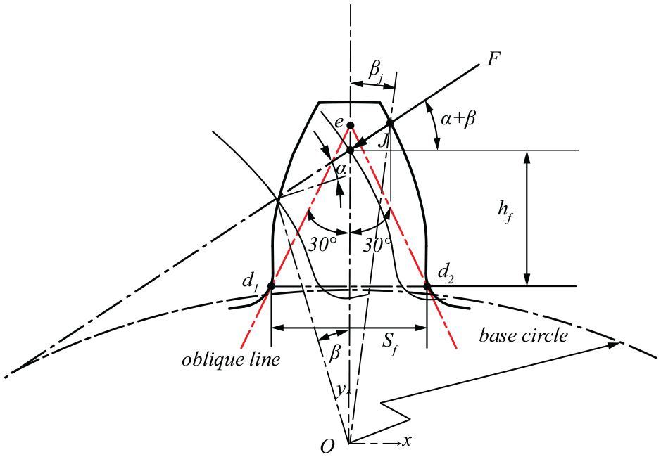
Calculation model of maximum root stress recommended ISO.
The tooth width is noted as

The bending stress can be evaluated by:
By establishing a coordinate system at the center of the gear,

the y coordinate of contact point yd can be obtained by solving the equations of the inscribed profiles and the profile of the fillet. The y coordinates of the switching point can be obtained by:

and

The tooth stiffness of the rolling gear
The calculation procedure of stiffness is shown in Figure 8. The calculation of stiffness consists of stiffness of axial compressive, bending, shear, and fillet foundation, which is related to geometry of tooth profile and material properties.
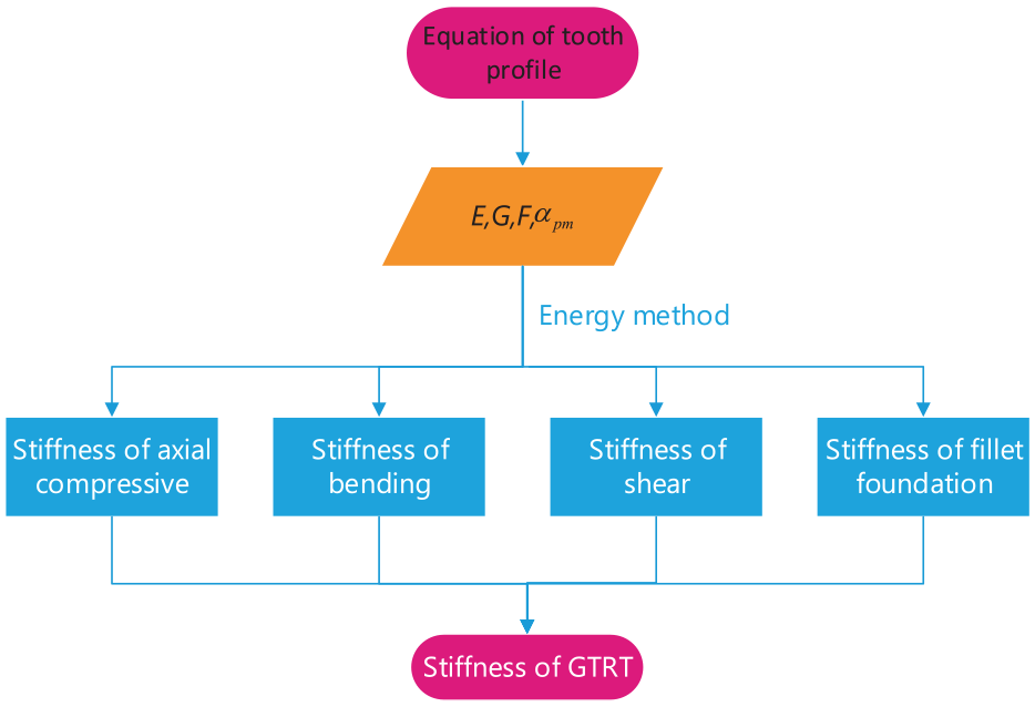
Calculation procedure of stiffness of gear tooth.
The profile of TRT is shown in Figure 9. The coordinate system xoy, located at the gear geometric center O, is utilized to express the tooth profile. Variables x and y are used to define the abscissas of points on the tooth profile. τ and αPm are pressure angles of the corresponding contact points on tooth profile. F is the contact force.
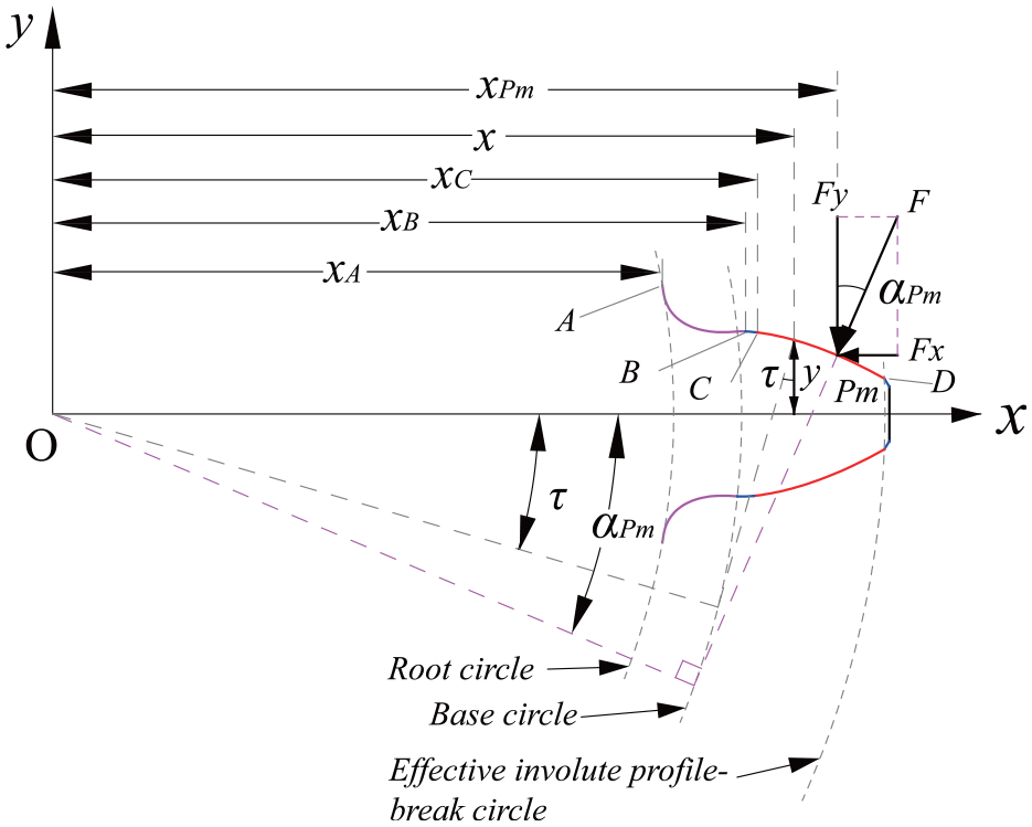
The tooth profile of the rolling tool. 16
Based on Ma et al., 17 the normal transition curve AB can be expressed as:
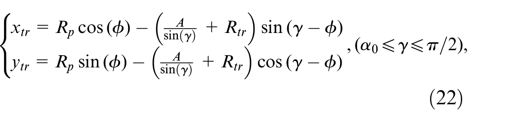
where
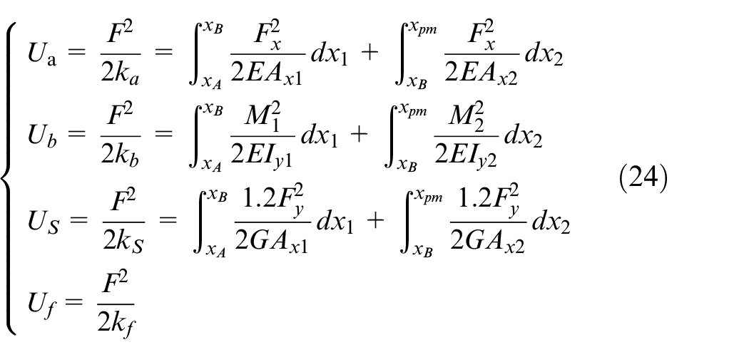
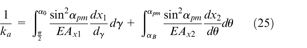
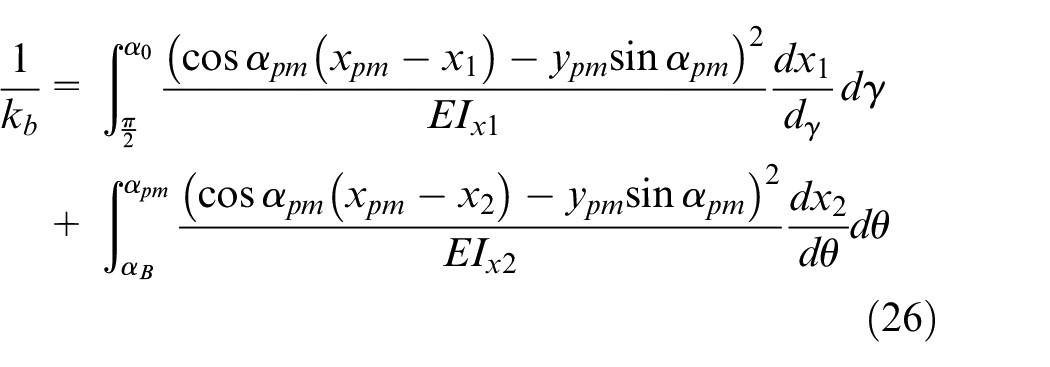
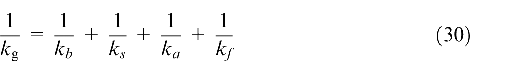
The tooth stiffness of the rolling tool can be evaluated by the energy method which can be expressed as 17 :
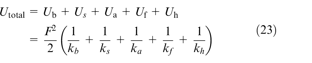
where Ua is the axial compressive energy, Ub is the bending energy, Us is the shear energy, Uf is the fillet foundation energy, Uh is Hertzian contact energy. The main target of this work is focused on the optimization of the general strength (stiffness) of the gear tooth due to the modification of the tooth transaction curve, which has no effects on the Hertzian contact energy (deformation of the contact point on the involute curve), and therefore it’s effect is neglected. The tooth stiffness of the rolling tool can be expressed as:
where F is contact force during the rolling process, and is assumed as tangent to the gear base circle, where
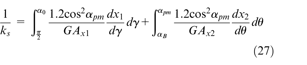
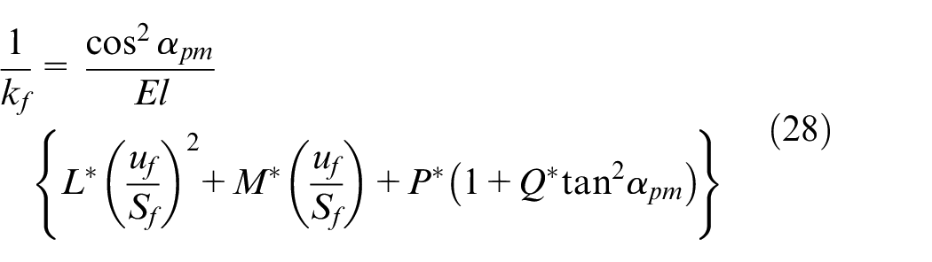
where
The stiffness of the gear tooth stiffness
The comparison of the maximum root stress
The maximum root stress is calculated with different coefficient of bottom clearances, contact ratio, modulus and type of the fillets for the selection of the proper parameters of rolling tools.
Different coefficients of bottom clearance
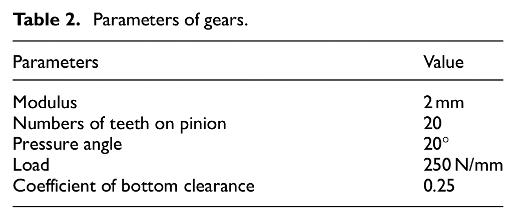
The maximum root equivalent stresses with different coefficients of bottom clearance are calculated. Other parameters are given in Table 2.
Parameters of gears.
The maximum root stresses of standard gear and optimized gear with different bottom clearances are shown in Figure 10. With the increasing of the bottom clearance, the maximum root equivalent stress with optimized transaction curve has a significant decrease. While the numbers of teeth on gear increasing from 10 to 100, the reduction ratio increases from 2.99% to 3.84% with ISO model while the coefficient of the bottom clearance is 0.25. The reduction ratio increases from 5.63% to 7.22% with ISO model while the coefficient of the bottom clearance is 0.2. The reduction ratio increases from 8.21% to 10.61% with ISO model while the coefficient of the bottom clearance is 0.15.
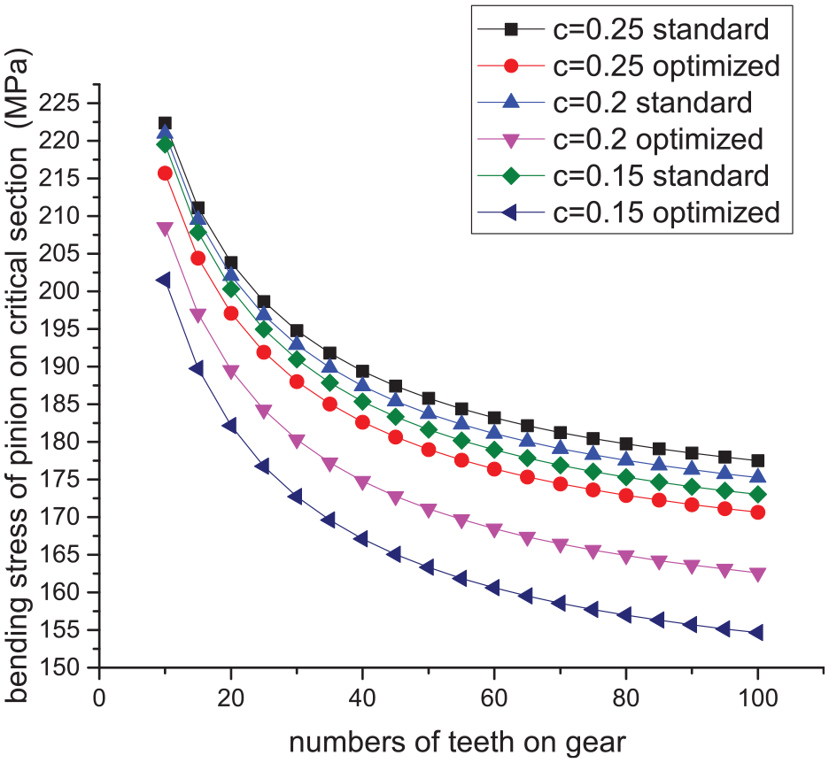
Maximum root equivalent stress for different coefficient of the bottom clearance.
Different pressure angles
The maximum root equivalent stresses with different pressure angles are calculated. Other parameters are given in Table 2. The maximum root stresses of standard gear and optimized gear with different pressure angles are shown in Figure 11. While the numbers of teeth on gear increasing from 10 to 100, the reduction ratio of maximum root stresses increases from 3.28% to 4.16% with ISO model while the pressure angle is 15°. The reduction ratio of maximum root stresses increases from 3.02% to 3.90% with ISO model while the pressure angle is 20°. The reduction ratio of maximum root stresses increases from 2.70% to 3.44% with ISO model while the pressure angle is 25°.
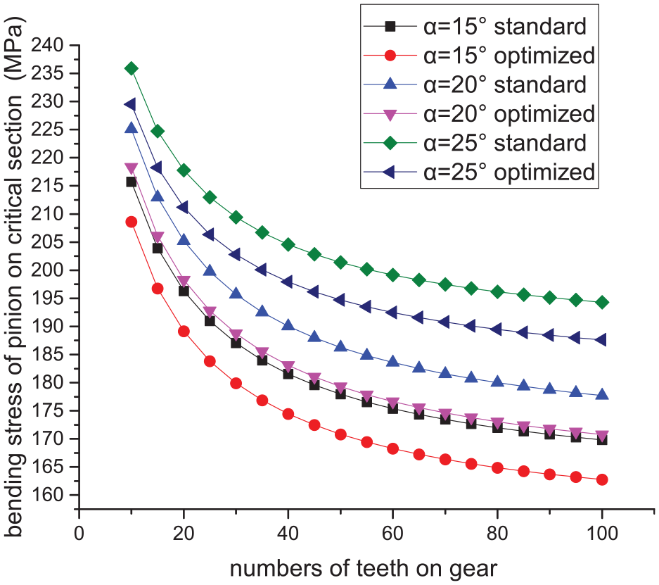
Maximum root equivalent stress for different numbers of teeth on gear.
Different modulus
The maximum root equivalent stresses with different modulus are calculated. Other parameters, for example, contact ratio, numbers of teeth on pinion, coefficient of bottom clearance, force, etc. are given in Table 2. The maximum root stresses of standard gear and optimized gear with different modulus are shown in Figure 12. The maximum root stress has a significant decrease with a larger modulus. While the numbers of teeth on gear increasing from 10 to 100, the reduction ratio of maximum root stresses increases from 2.99% to 3.84% with ISO model, but reduction ratio remains the same the modulus is 2, 4 or 6.
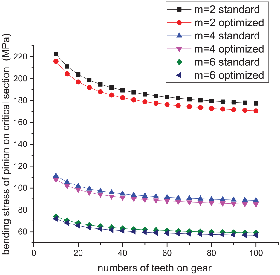
Maximum root equivalent stress for different numbers of teeth on gear.
A FEM model is calculated to verification the validity of theoretical model. HPSTC is calculated with the numbers of teeth on gear are 30. Applied a fixed constraint on the pinion hole and load a normal linear force 250 N/mm on the HPSTC with different transaction curve. As is shown in Figure 13. There are 125,380 linear hexahedral elements of type C3D8R in Finite Element mesh division and a single tooth is refined for more reliable result.
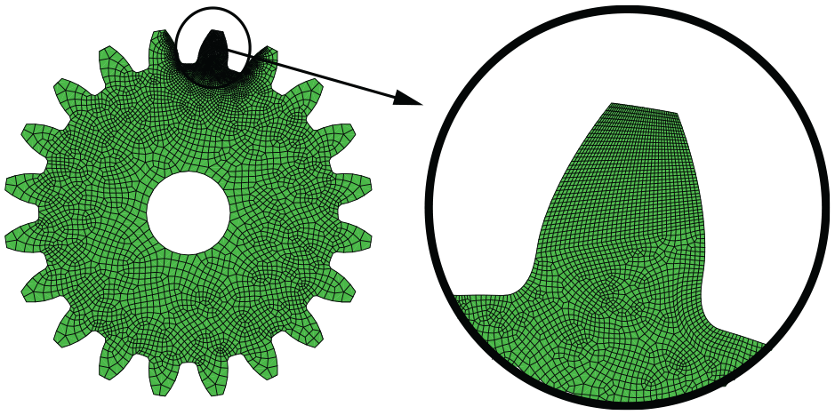
Finite element meshing model.
The results calculated by ABAQUS® is shown in Figure 14. The local stress concentration due to constraint was ignored. The maximum root stress are 283.9 MPa and 247 MPa calculated with optimized transaction curve and standard transaction curve. The maximum root stress of optimized transaction curve and standard transaction curve are 191.4 MPa and 172.8 MPa calculated by AGMA model or 191.0 MPa and 172.7 MPa calculated by ISO model. Although the FEM results are larger than the results calculated by AGMA or ISO model, the reduction percentage of maximum root stress are 15.0% calculated with FEM model, roughly equal to the reduction percentage calculated by AGMA model with its 11.0% or ISO model with its 11.1%.
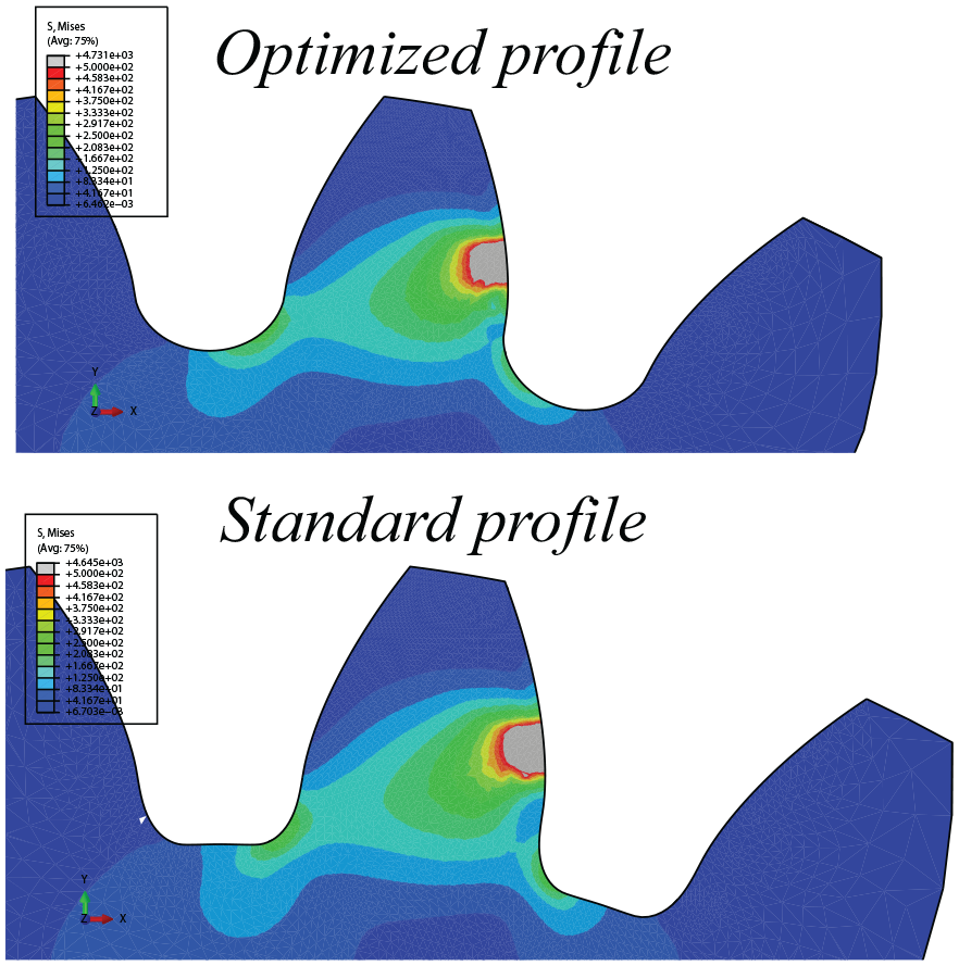
Stress distribution with optimized transaction curve and standard transaction curve.
The impact factors on the stiffness of rolling tool
Different coefficients of bottom clearance
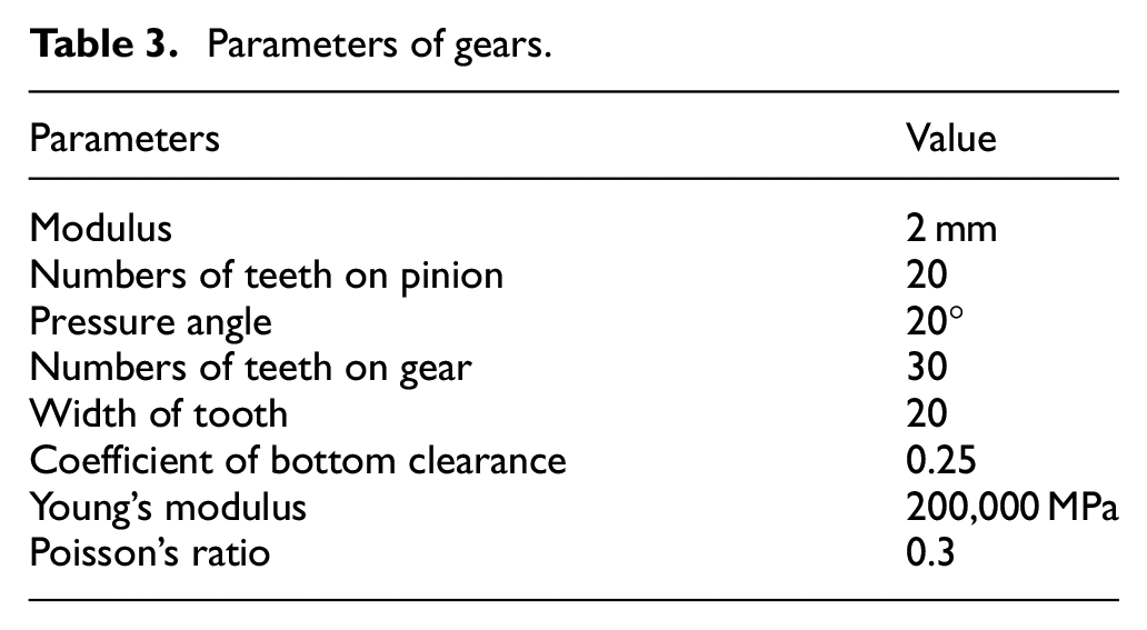
There are minor researches of forming force on the rolling tools during the rolling process so that the direction of the forming force was simplified to the same direction as the meshing force. Stiffness of rolling tools with different coefficients of bottom clearance are calculated. Other parameters are given in Table 3.
Parameters of gears.
Stiffness of standard and optimized rolling tools with different coefficients of bottom clearances are shown in Figure 15. With the increasing of the rotational angles of workpiece, stiffness of rolling tools has a significant increase. While coefficients of bottom clearances increasing from 0.15 to 0.25, stiffness of rolling tools has a slightly decrease. The maximum stiffness of optimized profile increased by 11.37%, 12.50%, and 12.53% while the coefficients of bottom clearances are 0.15, 0.20, and 0.25, respectively. The minimum stiffness of optimized profile increased by 6.82%, 7.83%, and 8.76% while the coefficients of bottom clearances are 0.15, 0.20, and 0.25, respectively.
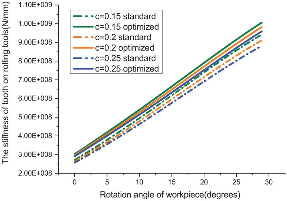
Stiffness of standard gear and optimized rolling tools with different coefficient of the bottom clearance.
Different pressure angles
Stiffness of standard and optimized rolling tools with different pressure angles are calculated. Other parameters are given in Table 3. Stiffness of standard and optimized rolling tools with different pressure angles are shown in Figure 16. With the increasing of the rotational angles of workpiece, stiffness of rolling tools has a significant increase. While coefficients of pressure angles increasing from 20° to 30°, stiffness of rolling tools has a slightly increase. The maximum stiffness of optimized profile increased by 8.76%, 6.38%, and 6.24% while the pressure angles are 20°, 25°, and 30°, respectively. The minimum stiffness of optimized profile increased by 13.53%, 8.10%, and 5.51% while the pressure angles are 20°, 25°, and 30°, respectively.
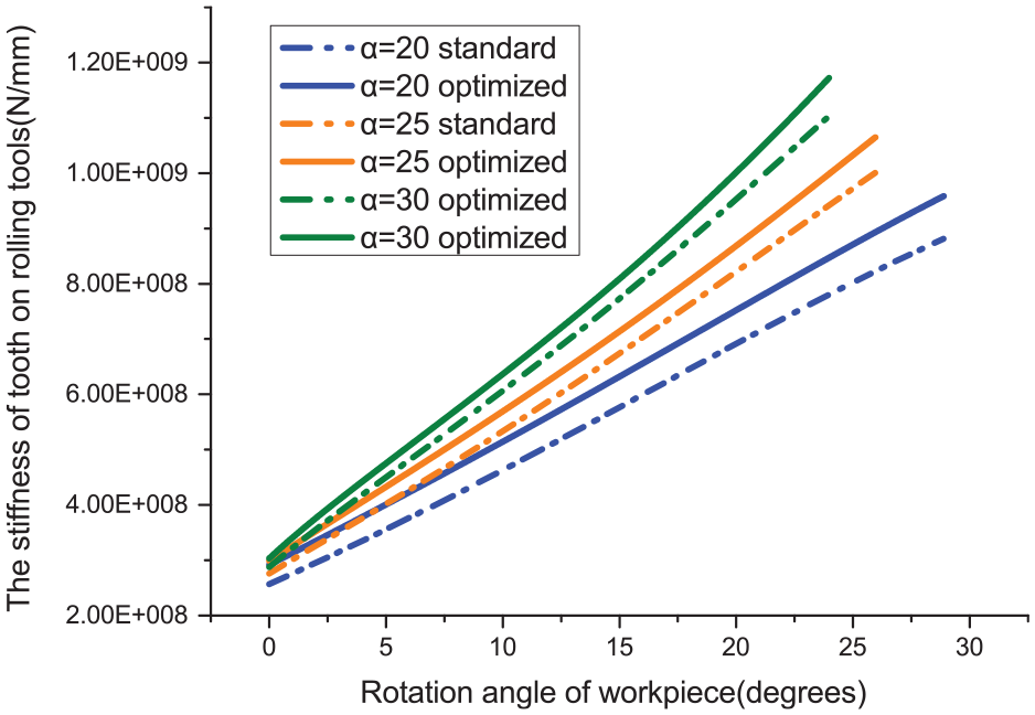
Stiffness of standard gear and optimized rolling tools with different pressure angles.
Different modulus
Stiffness of standard and optimized rolling tools with different modulus are calculated. Contact ratio, numbers of teeth on pinion, coefficient of bottom clearance, force, etc. are given in Table 3. Stiffness of standard and optimized rolling tools with different modulus are shown in Figure 17. With the increasing of the rotational angles of workpiece, stiffness of rolling tools has a significant increase. While modulus increasing from 2 to 4, stiffness of rolling tools has a slightly increase. The maximum stiffness of optimized profile increased by 13.53%, 12.27%, and 10.97% for the modulus of 2, 3, and 4, respectively. The minimum stiffness of optimized profile increased by 8.76%, 6.42%, and 4.75% for the modulus of 2°, 3°, and 4°, respectively.
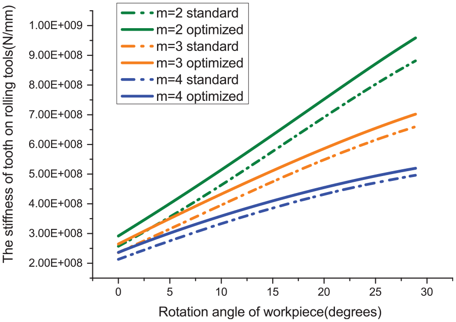
Stiffness of standard gear and optimized rolling tools with different modulus.
Conclusion
In this paper, the concept of elliptical fillet of the gear was proposed for gear rolling tool to reduce the maximum root stress and strengthen stiffness. The maximum root equivalent stress and the meshing stiffness ware calculated with mathematical models with different clearance coefficients, modulus, pressure angle considered. The following conclusions can be summarized:
The optimization of the TRT are proved to be effective under the same other design parameters such as modulus, numbers of tooth, pressure angles, and the coefficient of bottom clearance. A smaller coefficient of bottom clearance can maximize the optimization of proposed tooth profile while the root stress decreased by about 10% with changing the coefficient from 0.25 to 0.15.
The stiffness of gear rolling tool during the rolling process are investigated. It can be seen that the selection of smaller modulus, coefficients of bottom clearance, and larger pressure angles can significantly increase the stiffness of rolling tool. Also, the effectiveness of the proposed transaction curve is validated by comparison to normal transaction curve. The optimization of tooth profile has about 8.76% to 13.53% increase on the maximum stiffness of the rolling tool based on the given parameters.
The calculation model of stiffness of rolling tool will lead to precise prediction of deflection. In further research, the model can be used for further optimization of TRT or the compensation of rolling tool deflection for achieving high profile accuracy product in the gear forming process.
Footnotes
Declaration of conflicting interests
The author(s) declared no potential conflicts of interest with respect to the research, authorship, and/or publication of this article.
Funding
The author(s) disclosed receipt of the following financial support for the research, authorship, and/or publication of this article: This project was supported by the National Natural Science Foundation of China (no. 51775062 and no. 51905052).