
Abstract
Microstrutured surfaces can be manufactured by roll-to-roll process with roller mold in a high precision and high efficient way. The roller mold machined by drum roll lathe has a large cutting area and takes long time, and thus, the machining precision of roller mold is very sensitive to the thermal error of machine tool. This study analyzes the influence of thermal error on the machining horizontal grooves array on roller mold and proposed a processing method to improve the machining precision. First, the thermal error of hydrostatic guideways system in drum roll lathe was analyzed by simulation and measured through experiments, respectively. Given the diamond tool position offset caused by thermal error, the pitch error of horizontal grooves array with sequential cutting method was discussed. And then, multi-divisions cutting method is proposed to average the pitch error to multiple horizontal grooves instead of cumulative error in the seam position of horizontal grooves array, compared with sequential cutting method. Finally, the experiments with Four Divisions Method were carried out to verify the validity of multi-divisions cutting method. The experimental results demonstrate that multi-divisions cutting method can considerably improve the machining precision of horizontal grooves array.
Introduction
Due to the microstructured surfaces possessing additional freedom to create novel functions or combinations, 1 large numbers of functional surface products have emerged in the innovative applications, such as energy transfer, microfluidics, micro-optics 2 and self-cleaning fields. 3 Currently, with requirements of mass production of large area functional surfaces, roll-to-roll (RTR) process is considered to be an advanced manufacturing technology. 4 As the critical component in the RTR process, roller mold with microstructured surfaces is used to imprint the high-precision surface microstructures onto the plastic substrate. 5 Many researchers have started related studies about machining microstructures on roller mold. Zhang and colleagues6,7 experimentally investigated the complete manufacturing cycle of linear Fresnel lens polymer film and radial Fresnel lens on roller mold in terms of the machining of roller mold, RTR embossing and measurement test on film profile and functionality. Liu et al. 8 studied the diamond turning machinability of high-precision RTR roller molds used for subwavelength gratings; the results show that cutting speed was the most critical factor causing irregular grating periods. Duong et al. 9 researched the relationships among cutting conditions, cutting force and deformation by means of theory and experiments for the rectangular micro-pattern machining on roller mold. Qiao et al. 10 investigated the influences of cutting parameters on the burr height for micro V-grooves ultraprecision machining on roll die, such as cutting depth, the included angle of V-shaped diamond tool and the multi-step cutting depth. Tae-Jin et al. 11 established the machining mechanism of multiple threads for the complex prism patterns on the large-size electroplated roller mold.
The literature review shows that a substantial amount of research has been focused on the effect of cutting parameters on machining quality and innovative cutting methods for sorts of complex microstructured surfaces. However, relatively few investigations have been found on the effect of thermal error on the machining precision of roller mold. Although many researchers12–16 have made great efforts on the studies about thermal error of machine tools, which mainly include the measurement of temperature and displacement, the simulation and compensation of thermal error of machine tool, machining process was seldom used to reduce the machining error of microstructures caused by thermal error of machine tool. Thus, motivated by this deficiency, this study develops a multi-divisions cutting method (MCM) method for horizontal grooves array (HGA) ultraprecision machining to reduce the pitch error induced by thermal error of machine tools.
Thermal error of hydrostatic guideways system in drum roll lathe
Configuration of drum roll lathe
The drum roll lathe (DRL) is a home-made ultraprecision machine tool which consists of dual aerostatic spindles denoted as a spindle or C axis and two closed hydrostatic guideways denoted as X- and Z-axes, respectively, as shown in Figure 1(a). In addition, dual aerostatic spindles are headstock spindle and tailstock spindle, respectively, which are employed to support the large-size and heavy roller mold, and thus, the spindles are mounted on the bed. X- and Z-axes are designed as hydrostatic guideways system (HGS) with cross slide layout, in which X axis is fixed on the Z-axis carriage and carries the diamond tool and tool holder. X- and Z-axes are directly driven by linear motor, which have advantages of high accuracy and rapid response.
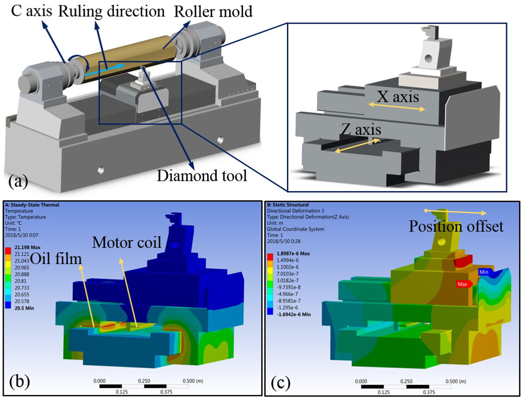
The thermal analysis of HGS: (a) simplified model of DRL and HGS, (b) temperature contour of HGS, and (c) thermal deformation of HGS.
For the ultraprecision machining of HGA, the spindle is set as C axis mode to control the high resolution motion of roller mold, and Z axis drives X axis and diamond tool to complete the cutting of horizontal grooves with high-speed reciprocating motion. In the cutting process, the thermal issues produced by ambient temperature and power consumption of machine tool are inevitable. Thermal deformation of roller mold mainly occurred in axial direction,12,17 which will not affect the pitch precision of HGA in circumferential direction. However, the pitch error of HGA may be generated due to the thermal deformation of HGS.
The steady state thermal-structural simulation for HGS
Before thermal simulation, the heat sources acting on HGS should be clear, which can be divided into the inner and outer heat sources according to the machine tool working conditions. The inner heat sources contain the heat consumption of linear motor coil, the heat induced by oil film shear and the heat induced by power loss when the high pressure oil flows to the ambient via oil pads and orifices. The outer heat source mainly depends on the ambient temperature variation.
To study the influences of thermal error on the diamond tool position, steady state thermal simulation of HGS was carried out by using ANSYS Workbench 2017. The simulation parameters were set according to Table 1 after entering the HGS finite element model (FEM) model. Figure 1(b) shows the temperature contour of HGS, and it can be observed that high temperature areas are mainly located in the oil pads and the linear motor coil of Z axis. The temperature of X axis rises by 0.5 °C mainly due to the ambient temperature variation. After thermal simulation, the temperature field data of HGS were imported into mechanical model to analyze the static deformation of HGS caused by temperature variation. As can be seen in Figure 1(c), the diamond tool moves away from roller mold surface up to 1.2 μm under the influence of HGS thermal deformation. As a result, the pitch precision of HGA on roller mold can be affected by the position offset of diamond tool.
The steady state thermal simulation parameters.
The measurement of tool position offset and temperature variation
According to steady state thermal-structural simulation results of HGS, the measurement of tool position offset as well as ambient and oil temperature variation were achieved by capacitance micrometers and thermocouple thermometers, respectively, as is shown in Figure 2(a). The workpiece was first mirror finished by diamond tool turning. To measure the change of displacement between the workpiece and diamond tool, the capacitance probe was fixed in the diamond tool position and the clearance between probe and workpiece was adjusted accurately within effective measurement range of capacitance micrometer. The thermocouple thermometers were placed around the tool holder and in the oil tank, respectively. The data acquisition software in PC recorded the displacement and temperature data with the same sampling frequency. Figure 2(b) exhibits the diamond tool position offset and temperature variation, the diamond tool position was offset to 0.7 μm as the ambient temperature rose to 23.2 °C. As there was a further increase in the ambient temperature from 23.2 °C to 23.6 °C, the diamond tool position was offset up to 1.6 μm. The oil temperature rose very slowly, only 0.2 °C rise happened during the measurement process, and the main reason is that the measuring position is the oil tank with cooling unit instead of oil pad position, subjected to the Z-axis rapid motion. The measurement results indicate that the large clearance is put between diamond tool and workpiece as the rise of ambient and oil temperature, which changes the cutting depth and also leads to machining error for HGA.
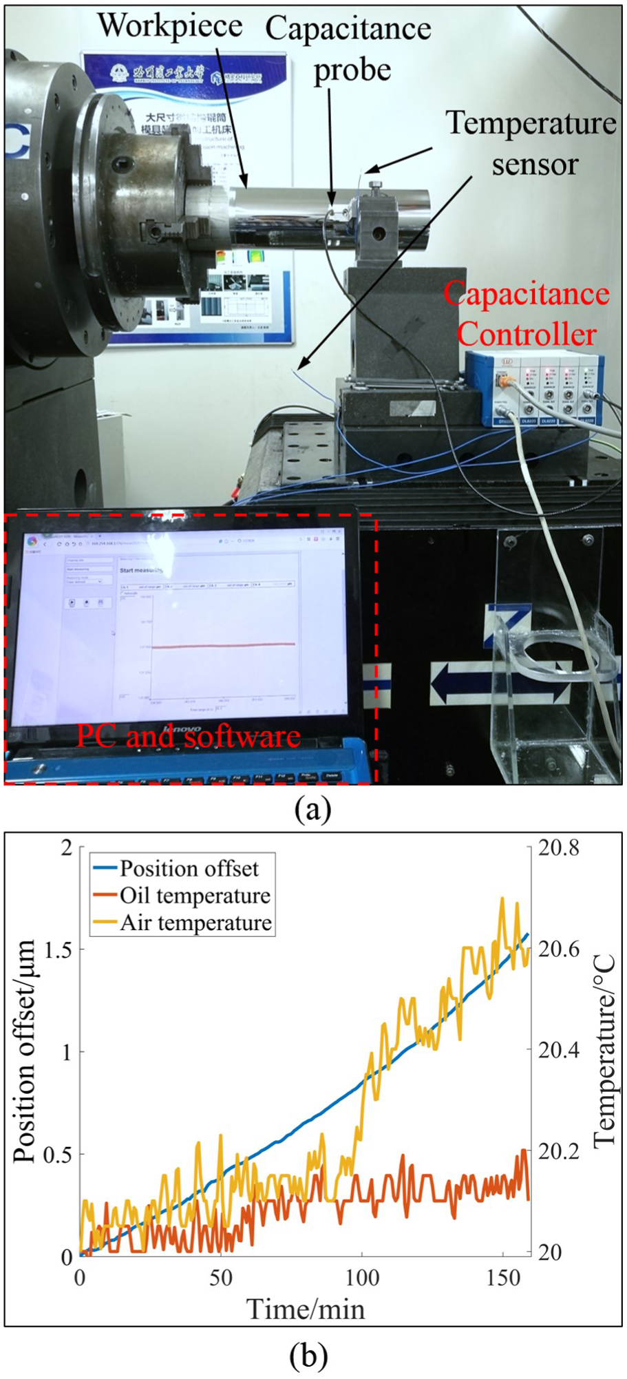
Measurement results of temperature and diamond tool position offset: (a) the setup of measurement and (b) position offset and temperature variation.
Average effect of MCM on thermal error
In this study, the roller mold diameter is 270 mm, and the overall horizontal grooves number and the designed groove pitch are set to be 4240 and 200 μm, respectively. In addition, each groove pitch is generated by cutting interference with neighboring grooves, 10 that is to say, pitch precision of each groove is affected by the cutting depth of three adjacent grooves. Figure 3 shows the pitch error analysis of MCM for HGA. As can be seen in Figure 3(a), the diamond tool position offset is assumed to be 2 μm which is regarded as linear proportional relation with grooves number in the circumference of roller mold; the cutting depth is smaller as position offset of diamond tool gets larger.
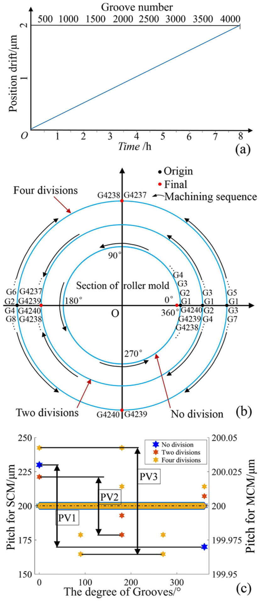
The pitch error analysis of MCM: (a) the assumed temperature variation, (b) three kind of cutting methods, and (c) the pitch error analysis of different cutting methods.
Figure 3(b) reveals the principle of different cutting methods, including sequential cutting method (SCM) (No division), Two Divisions Method and Four Divisions Method, both the origin and final positions belong to seams at which larger pitch error exist. The SCM means that the grooves are machined sequentially in the same direction of roller mold circumference; the first and last grooves meet at the seam where large pitch error occurs due to the large difference in cutting depth between G1 and G4240. Two Divisions Method divides the circumference of roller mold into two parts in which grooves are machined alternately, and the sequence numbers of adjacent grooves at the seam are successive; this leads to smaller pitch error at the origin and final position due to the slight differences in cutting depth of adjacent grooves. In addition, with the exception of grooves at seams, the difference between sequence numbers of other adjacent grooves are two, so the grooves keep smaller pitch error. For Four Divisions Method, there are two origin and final positions at which the sequence number difference of adjacent grooves are two and one, respectively, and the sequence number differences of other adjacent grooves except grooves at seams are four.
Following the illustration for different cutting methods, the pitch error is calculated as shown in Figure 3(c). The PV values of pitch error for SCM, Two Divisions Method and Four Divisions Method are 60 μm, 50 nm and 75 nm, respectively. Therefore, the MCM can apparently decrease the pitch error at the origin or final position compared with SCM. The Four Divisions Method has larger sequence number differences at the seams in comparison to Two Divisions Method; Hence, the pitch error of the seams is slightly bigger than that of Two Divisions Method, which suggests that the PV value of pitch error is bigger as the division number of roller mold circumference increases. As a result, Two Divisions Method is superior to other cutting methods to reduce the effect of thermal error on the pitch precision of HGA.
Experimental results and discussion
In this study, two groups of experiments were carried out. One is to exhibit the effect of thermal error on the pitch precision with SCM and the other is to find the average effect of MCM on the thermal error. The experiments employed electroplated copper roller mold with high cutting machinability, and the overall cutting length of roller mold was 1800 mm. Considering the length occupied by acceleration and deceleration of Z axis, the effective cutting length for horizontal grooves was about 1500 mm. The experimental parameters are listed in Table 2. The overcutting depth was set as 2 μm to make sure the actual cutting depth is greater than nominal cutting depth, considering the thermal error of HGS.
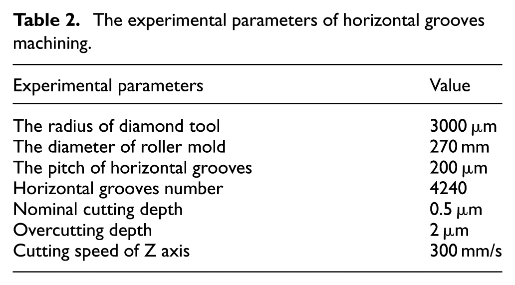
The experimental parameters of horizontal grooves machining.
The machining and measurement results of HGA with SCM are shown in Figure 4. For the convenience of measurement, horizontal grooves on roller mold were imprinted to the polyester (PET) film with ultraviolet (UV) cure equipment in RTR process, and then the high quality optical film with HGA was obtained in Figure 4(b), which was measured by Olympus STM-6 optical microscope in Figure 4(c). The measurement results are shown in Figure 4(d); both G1 and G4240 have large pitch error at the seam due to the drastic change of cutting depth caused by HGS thermal error, and G4240 pitch is less than 200 μm, which results from the lesser cutting depth. The other grooves pitch except G1 and G4240 keep slightly larger than the designed value because of the optical film water swelling, and this kind of pitch error is acceptable.
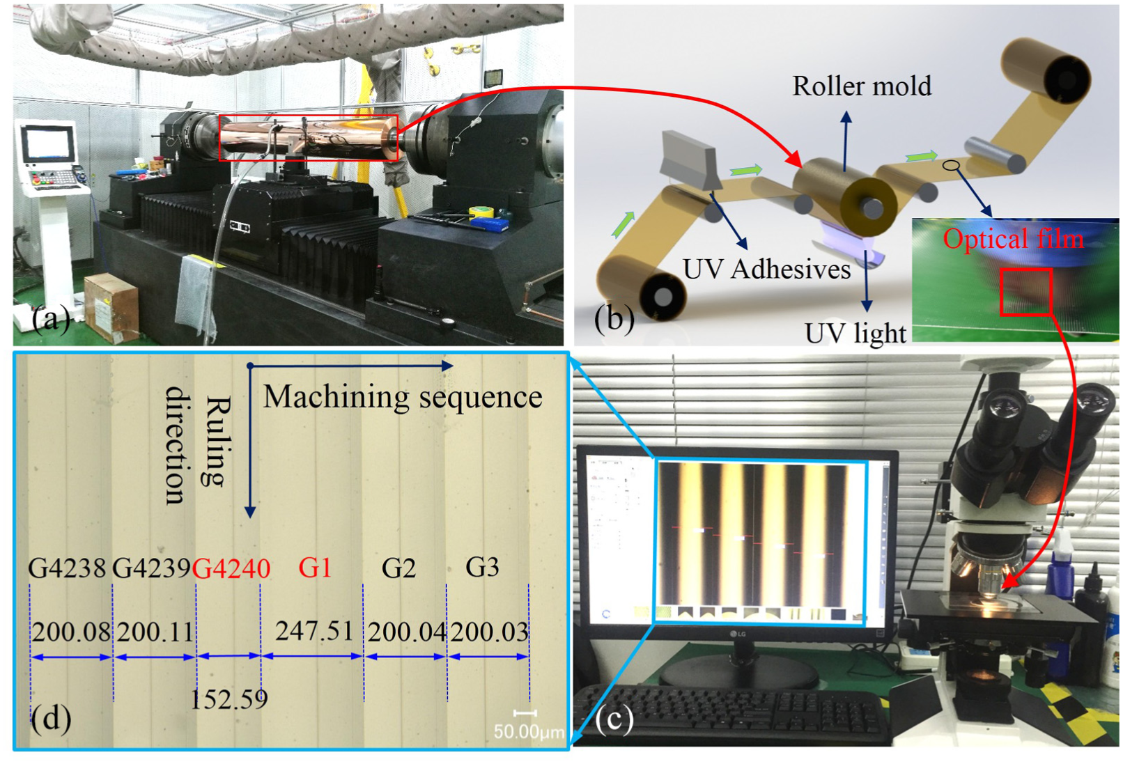
The machining and measurement of HGA with SCM: (a) the picture of DRL-1800, (b) RTR process, (c) the measurement setup of microstructured film, and (d) the pitch error at the seam.
As is shown in Figure 5, the horizontal grooves with Four Divisions Method were measured. To verify the average effect of MCM on thermal error, the HGA with Four Divisions Method were machined on roller mold, and the imprinted optical film at roll mold position 0°, 90°, 180° and 270° were measured. The pitch results are presented in Figure 5(a)–(d), respectively. No large pitch error takes place at four seams, and the range of pitch error is from10 nm to 60 nm so as to beyond the precision capability of microscope, only 0.005% to 0.03% of the designed pitch value. With the high pitch precision of horizontal grooves, it can be concluded that MCM can greatly average the pitch error, from one seam to four seams, caused by HGS thermal error.
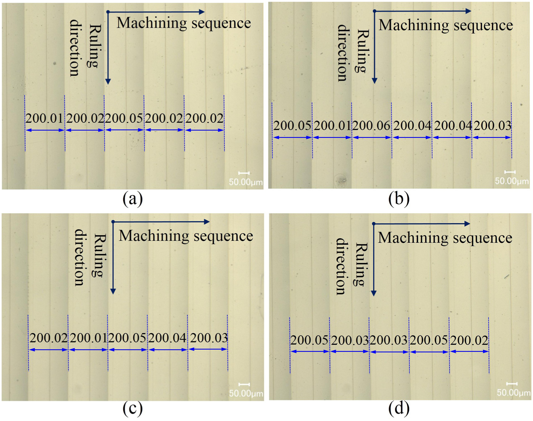
The measurement results of horizontal grooves pitch with Four Divisions Method: (a) the pitch results at position 0°, (b) the pitch results at position 90°, (c) the pitch results at position 180°, and (d) the pitch results at position 270°.
Conclusion
Compared with SCM, the average effect of MCM on the thermal error caused by HGS thermal deformation is verified by cutting experiments. Based on the results of experiments, some conclusions can be drawn:
The HGS thermal-structural simulation shows that the diamond tool moves away from roller mold surface up to 1.2 μm.
The position offset of diamond tool as well as ambient and oil temperature variation are measured respectively. The relationships between position offset and temperature are basically accordant with HGS thermal-structural simulation results.
With the pitch error analysis of MCM, Two and Four Divisions Methods are recommended due to the smaller machining sequence difference between adjacent grooves on roller mold.
The HGA with Four Divisions Method is machined on roller mold; the pitch measurement results indicate that MCM can greatly decrease the pitch error caused by HGS thermal error.
Footnotes
Declaration of conflicting interests
The author(s) declared no potential conflicts of interest with respect to the research, authorship, and/or publication of this article.
Funding
The author(s) disclosed receipt of the following financial support for the research, authorship, and/or publication of this article: This work was supported by Chinese National Natural Science Foundation (Grant No. 51605119).