
Abstract
Selective laser heat treatment is a well-known process for its ability to produce tailor heat treated blanks (THTB). Specifically, ultra high strength boron steels with tailored material properties can be produced. However, this process generates unwanted distortion and influences geometrical variation. This in turn can affect functionality, aesthetics, and performance of the final product. Understanding the effects on geometrical variation in the final product or the assembly will enable in designing and producing geometry assured products. In this paper, boron steel blanks were selectively laser heat treated with a specific heat treatment pattern and laser heating direction sequence. These heat treated blanks were then cold formed. Further on, spot welding simulation of the cold formed parts was performed to assess the effect on geometrical variation at the assembly level. The results show that the effect of selective laser heat treatment on geometrical variation at part level propagates further to the assembly level. It implies that the effect on geometrical variation should be minimized at part level, when the blanks are laser heat treated. Hence, the sources that influence geometrical variation at part level when employing selective laser heat treatment are presented and discussed. The motivation and possibilities to minimize the effects in the early design concept stages is provided.
Keywords
Introduction
The automotive industry is continuously working toward the objective of curbing the vehicle CO2 emissions. Controlling the vehicle weight is one common approach adopted by the industry to do so. Ultra high strength steels (UHSS) such as boron steels are used in the vehicle body to fulfill this objective while maintaining the safety requirements as it offers high strength to weight ratio. Hardened boron steels were first used in vehicles in 1984 1 and their usage has increased ever since. However, formability issues of UHSS restrict their usage to their full potential. Additionally, wide range of customer requirements demand for flexible processes with shorter processing time. Selective laser heat treatment is an innovative process that could be employed to overcome such issues.
Selective laser heat treatment process involves locally modifying material properties by heating the pre-determined local areas of the metal blank. The local areas can be pre-determined based on the forming requirements or functional requirements of the component to be manufactured. If there are multiple areas that require local modification, a heat treatment layout in the form of a pattern can be considered.2,3 Such locally modified blanks through heat treatment are commonly addressed as tailor heat treated blanks (THTB). 4 Laser as a heat source offers tremendous flexibility which allows local heat treatment to produce complex shaped parts as well. In comparison to conventional furnace heating, this process utilizes lesser energy as only desired areas are to be heated. The overall processing time can hence be reduced. These advantages make selective laser heat treatment a promising and an attractive manufacturing process.
Performing local laser heat treatment to enhance formability has been widely shown in case of aluminum alloys in various studies.5–8 In case of high strength steels, the prospects to enhance formability as well as reinforce strength locally have been investigated thus far. Dual phase steels such as DP 600, DP 1000, and Martensitic steel MS-W 1200 were successfully tested to enhance formability using local laser heat treatment by Neugebauer et al. 9 A homogenized zoom-optics was developed to heat treat high strength martensitic steels and complex phase steels by Baumann et al. 10 Improvement in formability of the steels using this setup was verified too. Reinforcing strength by local heat treatment in dual phase steel DP 600 was shown by Asadi et al. 11 by examining the microstructural changes.
To explore possibilities of augmenting strength and formability a step further, different production routes for the selective laser heat treatment process were tested for boron steels by Asnafi et al. 12 By using a heat treatment layout in the form of a square grid pattern, outcome in terms of high hardness as well as reduced springback for boron steels were successfully shown. This concept was further investigated for square grid pattern of different sizes by Ramesh Sagar et al. 13 and their influence on formability was presented. Conrads et al. 14 demonstrated the application of local laser heat treatment to control crash behavior by imparting strength in case of advanced high strength steels. The study also demonstrated the influence of grid pattern size on crashworthiness of the locally laser heat treated components. Further on, an FE simulation approach based on the crash behavior requirements was developed by Conrads et al. 15 to identify the selective areas for laser heat treatment.
All the studies carried out using selective laser heat treatment thus far have shown promising outcomes for locally enhancing formability and strength. However, a common point of concern highlighted among all the above mentioned scientific works is the unwanted distortion and undesirable residual stresses arising from this process. It affects functionality, aesthetics and performance of the end product.16,17 Very limited information is available on the effect of selective laser heat treatment on geometrical variation, both at part level and at assembly level. Also, given the novelty of the selective laser heat treatment process, using the data from traditional manufacturing processes for geometrical variation simulation can be misleading because different laser process parameter settings will influence the nature of geometrical variation. Therefore, understanding the effects at different levels will aid in minimizing the effects on geometrical variation. It will enable in using this manufacturing technique to its fullest potential to produce geometry assured products with consistent quality.
Paper scope
This work aims to investigate the effect of selective laser heat treatment (SLHT) process on geometrical variation at part level as well as assembly level, a domain which requires further exploration. This is done so by first performing SLHT on boron steel blanks and then subsequently cold forming to a semi industrial flex-rail part. Geometrical variation of the distorted heat treated blanks is analyzed and its effect on the springback of flex-rail parts is shown to demonstrate the effect at part level. To demonstrate the effect at the assembly level, spot welding simulation on the flex-rail parts is performed. The assembly springback is then analyzed as the final step.
This paper is structured in the following manner. Section “Theory” provides background on selective laser heat treatment process, geometrical variation, and the concept of geometry assurance. The experimental investigation is described step by step in “Experimental method” section. The outcome of this investigation is shown in section 4 “Results.” In section 5, results are discussed and different possible sources from the laser heat treatment process contributing to geometrical variation are mapped and discussed. Section 6 concludes the paper.
Theory
The SLHT process and its mechanism with respect to boron steels is explained in detail in this section. Effect of the process mechanism on geometrical variation is presented. The concept of robust design and geometry assurance is explained. The activities involved in geometry assurance such as allocation of locating schemes, variation simulation of spot welding process are described.
Selective laser heat treatment process
The process setup for SLHT is shown in Figure 1. The setup usually consists of a laser source mounted on a robot. Solid state laser such as Nd: YAG, gas laser such as CO2 laser, semiconductor diode laser such as AlGaAs laser are some of the commonly used commercially available laser types. 18 The metal blank is fixated in its position using fixtures and clamps. The local heat treatment areas are selected based on functional or forming requirements of the product being manufactured. The areas in the sheet metal blank which are critical for the forming process or for the required crash behavior can be identified either through simulations or through experience from designing similar products. The heat treatment areas can be applied in the form of a pattern or a layout (stripe pattern) if there are multiple local areas that require modification as shown in Figure 1. As the forming behavior and crash behavior is dependent on the choice of material as well as sheet material thickness of the desired component, the pattern specifications can vary from product to product. The robot controls laser scanning speed and laser heating direction sequence to produce the pre-defined heat treatment pattern. SLHT can be carried out in ambient room temperature conditions.
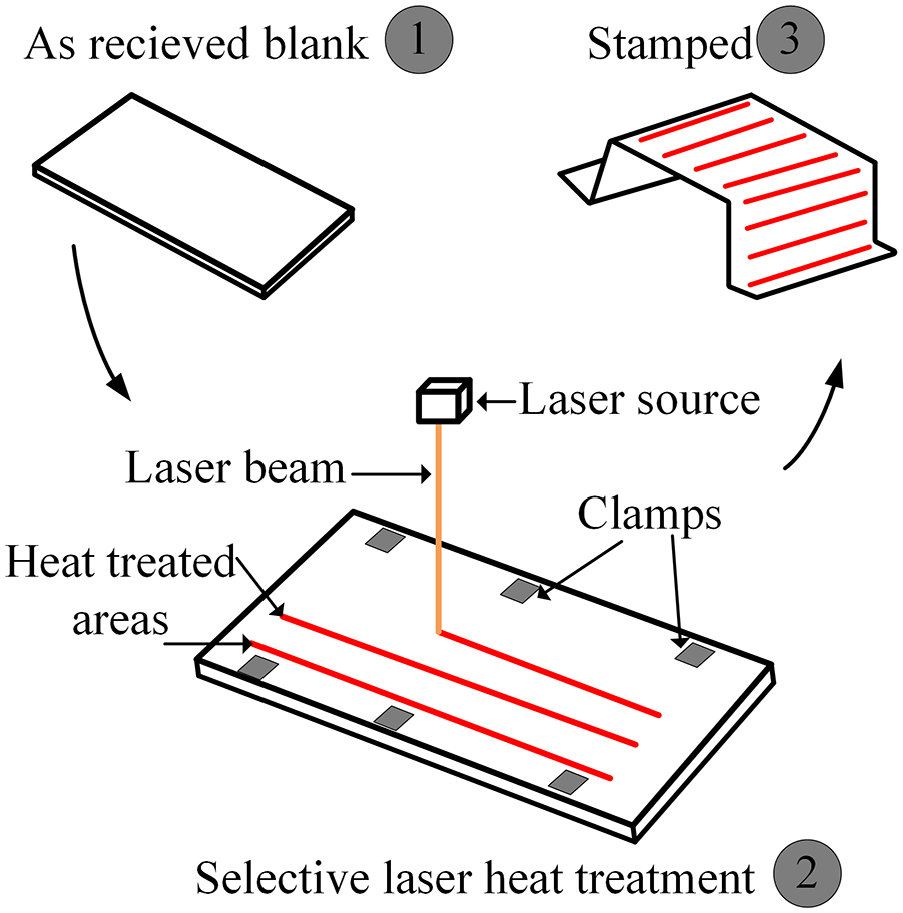
Selective laser heat treatment process setup.
When the laser beam is incident on the metal surface, the temperature starts to increase as the interaction continues. In case of boron steels, the microstructure starts to transform to austenite when temperature reaches around 750°C (Ac1). The transformation is complete to austenite when the temperature reaches around 880°C (Ac3). The Ac1 and Ac3 temperatures can vary based on the material composition. 19 As the laser moves on the surface as per the heat treatment pattern, the already heated areas begin to rapidly quench due to ambient conditions as well as presence of surrounding untreated areas of the metal blank. This rapid quenching causes the microstructure to undergo martensitic transformation and results in formation of the hardened area. 20
Thermal gradient and the microstructural transformation as a result of the SLHT process are the two main factors that affect the geometrical accuracy and distort the metal blank. 13 Initially, thermal gradient across the metal blank causes the heated area to expand which on transformation to austenite contracts in volume. Later, the transformation from austenite to martensite causes volumetric expansion. 21 Plastic deformation occurs when the stress due to thermal gradient as well as the microstructure transformation exceeds the yield stress of the material. This undesired distortion can further get affected as the metal blank is locked in its position using clamps. This mechanism involving the effect of thermal gradient and the microstructural transformation in case of boron steels is similar to martensitic expansion mechanism (MEM) referred to in laser forming techniques. 22 However, the purpose of SLHT is entirely different from that of laser forming technique. In laser forming, the purpose is to bend and form the metal as desired.23,24 While in SLHT, the main objective is to alter the local material properties without bending or distortion. Hence, distortion can be said to be an undesired by-product in this case.
Geometrical variation and geometry assurance
In every manufacturing process, the geometry of the parts being manufactured varies from the nominal geometry. Geometrical variation of the final assembled product stems from part variation, assembly variation, or from design concept variation. 25 Part variation is caused either due to variation in the manufacturing process or due to machine imprecision. They cause shape and size variation of the part. Assembly variation is caused by fixture variation or variation in the assembly process. The application of external forces through clamps or improper positioning of the part in the fixtures can further aggravate the geometrical variation and are considered as assembly variation sources.26,27 Most important source considered is the design concept of the product because a sensitive design will only amplify the part and assembly variation. However, a robust design concept can suppress the effect from other sources. 28
Robust design concept could be achieved through the geometry assurance process. Geometry assurance process consists of set of activities that guides in making early design changes in a product development process. Robust locating schemes, variation simulation and tolerance allocation are some of the activities performed in the geometry assurance process.
Locating scheme
The purpose of locating scheme is to lock the part during manufacturing, assembly or inspection. By having a robust locating scheme, the effect of variation can be minimized. A locating scheme is chosen to lock the parts with required degrees of freedom (DoF). Typically for rigid parts, a 3-2-1 locating scheme (Figure 2) is employed to lock the position. 29 Three locating points A1, A2, A3 lock three DoF, locating points B1 and B2 lock two DoF, while the locating point C1 locks the remaining one DoF. In case of non-rigid parts such as the sheet metal parts or assemblies, extra support points could be used wherever necessary.
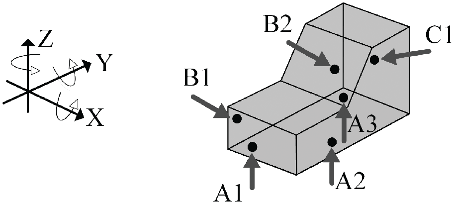
A 3-2-1 locating scheme.
In case of SLHT process, understanding effect on geometrical variation at part level is necessary, as it can impact subsequent assembly process. Apt locating schemes for different design concepts can then be chosen to minimize variation effects.
Simulation of the spot welding process
Various structural members are assembled together using Resistance Spot Welding process (RSW) in the automotive industry. The process consists of electrodes which hold the metal sheets together using the electrode force. As current is passed, a molten pool is generated at the interface of the metal sheets due to the resistance generated. This molten pool on cooling solidifies and results in a spot weld joining the metal sheets.
In the spot welding assembly process, the adjoining parts are first required to be positioned in a fixture and clamped such that all degrees of freedom are locked. Spot welding can then be performed in the preferred sequence to join the parts together. Once the joining process is complete, the assembly is unclamped. Unclamping causes the assembly to springback (Figure 3), the extent of which is influenced by springback of the formed part.
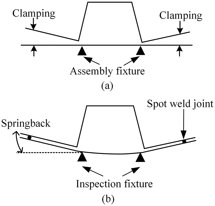
Spot welding assembly setup (a) Clamping prior to spot welding, (b) Springback after clamp release.
To perform the above mentioned steps in the variation simulation environment, several aspects such as establishing contacts to avoid part penetration, choice of spot weld gun (balanced or position) are vital. The fundamentals of contact modeling and variation simulation of the spot welding process has been widely discussed in,30–32 hence the details are not covered in this paper.
Experimental method
This section provides the specification of the material, the experimental setup and the tests performed. The sequence of steps in this study is depicted in Figure 4.
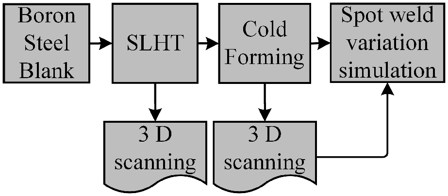
Sequence of steps followed in the experimental study.
In the first step, boron steel blanks were trimmed to the required dimensions. These trimmed blanks were laser heat treated according to a specific heat treatment pattern and a laser heating direction sequence, whose details will be explained in the later sub-section. Next, 3D laser scanning was performed to capture the geometry data of the distorted blanks. These laser heat treated blanks were then subjected to cold forming. A semi-industrial experimental forming tool, a flex-rail was used. 33 This flex-rail tool produces parts that replicates complex springback behavior of vehicle body parts. The formed flex-rail parts were then 3D laser scanned and the geometry data was used for springback analysis as well as for spot welding simulation.
A high speed non-contact 3D laser scanner (HP-L-8.9 laser scanner) with six-axis robot arm and accuracy of ±0.04 mm was used in the 3D scanning process to capture the data. 34 The 3D scanned data of laser heat treated blanks were used to assess geometrical variation in comparison with nominal geometry that is, computer aided design (CAD) geometry of the blank with no distortion. Geometrical variation analysis of heat treated blanks and the spot welding simulation process were carried out using Robust Design & Tolerance (RD&T) analysis software. 35 The software is equipped with multiple functions for analysis at different stages of design process.
Test setup
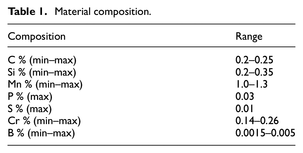
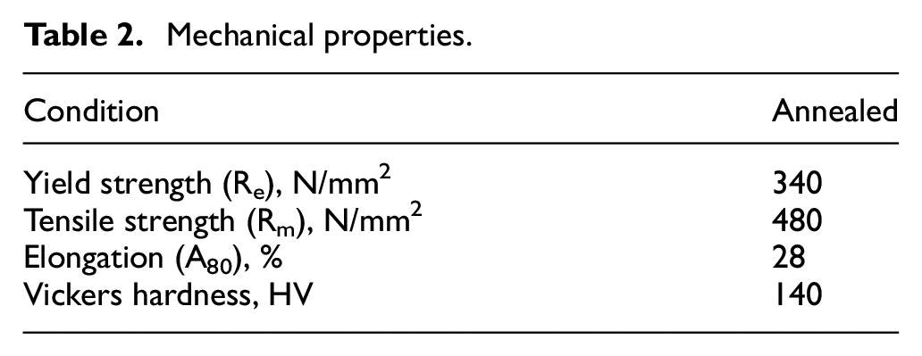
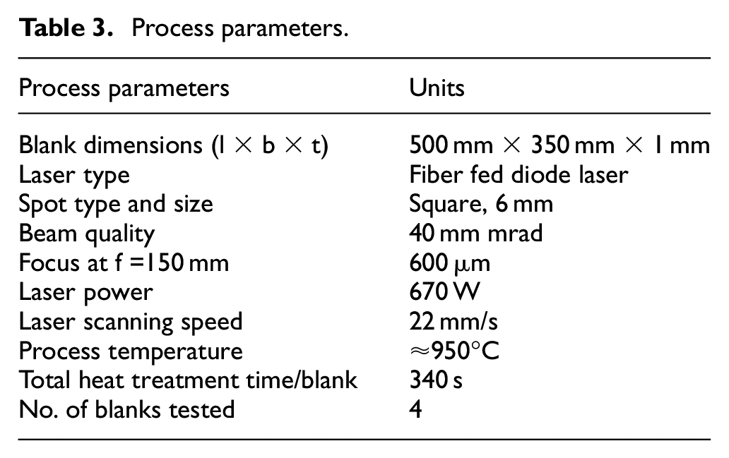
Boron steel grade named Boloc 02 was selectively laser heat treated. A fiber fed diode laser was the heat source. The material composition, mechanical properties, and the process parameters are listed in the below Tables 1–3. 36 The laser process parameters are based on the initial pilot study presented in Ramesh Sagar et al. 13
Material composition.
Mechanical properties.
Process parameters.
Heat treatment pattern
A square grid pattern with grid size of 50 mm was chosen for SLHT of the blank. The square grid heat treatment pattern was chosen based on the results from experimental pilot studies. 12 The grid size of 50 mm was chosen based on the influence of grid size on formability as investigated in. 13 Also, grid pattern forms an interesting case for influencing crashworthiness of vehicle body parts as highlighted in.14,15
The pattern was spread across the blank (Figure 5). The pattern was center positioned, equidistant from all the edges of the blank. The grid pattern dimensions provide sufficient spacing between alternating harder and soft zones. The harder zones are a result of SLHT while the soft zones are the untreated areas of the blank.
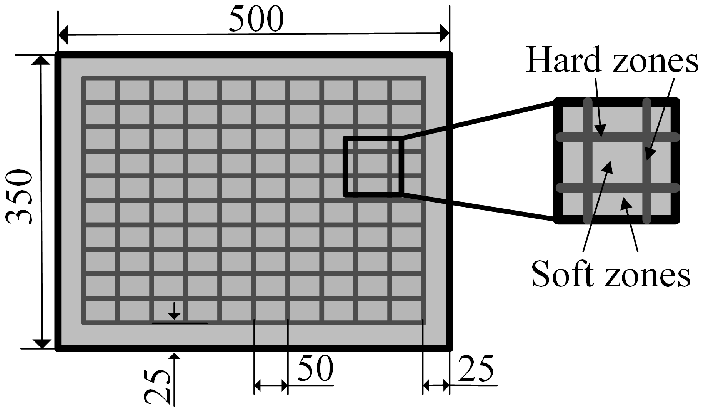
Heat treatment pattern. All units in mm.
Laser heating direction sequence strategy
The laser source was input with a laser heating direction sequence for applying the required heat treatment pattern. A sequence was chosen where the blank was heated along the rolling direction first (Figure 6(a)), followed by heating across to the rolling direction (Figure 6(b)).
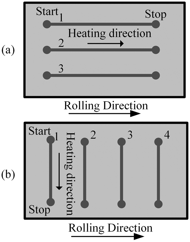
Heat treatment sequence (a) Heating along the longitudinal direction, (b) Heating along the transverse direction.
Forming
Initial tryouts during the pilot studies 12 to form a flex-rail with binder pressure of 100 bar led to cracks as shown in Figure 7(a). As a solution, the blanks were trimmed, formed with reduced binder pressure of 90 bar as well as shimmed with respect to sheet thickness of 1 mm to prevent cracks. The laser heat treatment pattern was then adjusted accordingly along the trimmed area (Figure 7(b)). The required press force to form an untreated blank was 100 kN while for the laser heat treated blanks it was 110 kN.
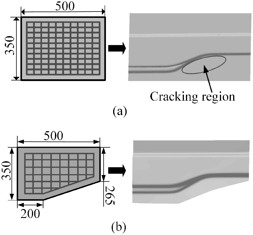
Modifications based on try-outs (a) Initial blank dimensions leading to cracks, (b) Crack-free formed flex-rail after modifications. All units in mm.
Positioning system
The boron steel blanks were fixated on the work table using a 3-2-1 locating scheme before performing SLHT. The clamps C1, C2, C3 assisted in fixing three translation and three rotation movements along X, Y, Z directions. An extra support clamp C4 was also used to fix the blank due to their compliant nature (Figure 8).
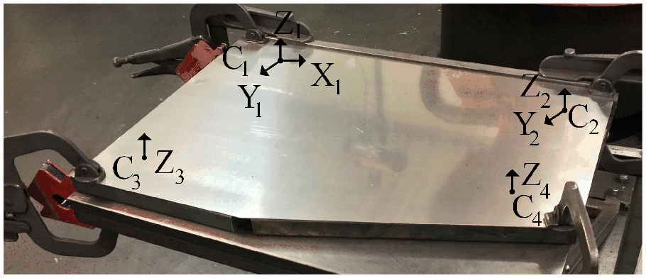
Positioning system used in selective laser heat treatment.
A 3-2-1 positioning system fixture was used for 3D scanning the laser heat treated blanks as well the formed parts (Figure 9). Total of four blanks underwent laser heat treatment and were inspected to check for repeatability of results and geometrical variation. The scanned data from the 3D laser scanner consisted of point cloud data.
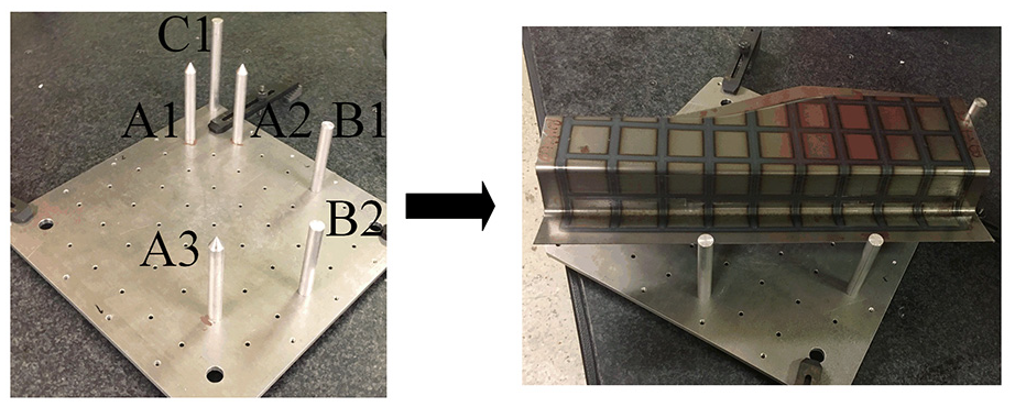
3-2-1 positioning fixture for 3D-laser scanning inspection.
Spot welding simulation setup
The 3D scanned data of the flex-rail parts were used for the spot welding variation simulation process as per the procedure explained in the theory section. The virtual setup consists of a sub assembly of flex-rail part positioned on a blank as shown in Figure 10. The 3-2-1 positioning system with extra support points were used to lock the parts together as per step 2 in Figure 10. Total of 28 spot weld points (WP) were used to join the parts together. The distance between each spot weld point was 35 mm. Simultaneous welding was opted to avoid the effect of welding sequence. The clamps were released after joining process was complete. The displacement of the spot welding points from their nominal position due to assembly springback was measured. The numbering of weld points and the inspection fixture positioning is shown in step 3 in Figure 10.
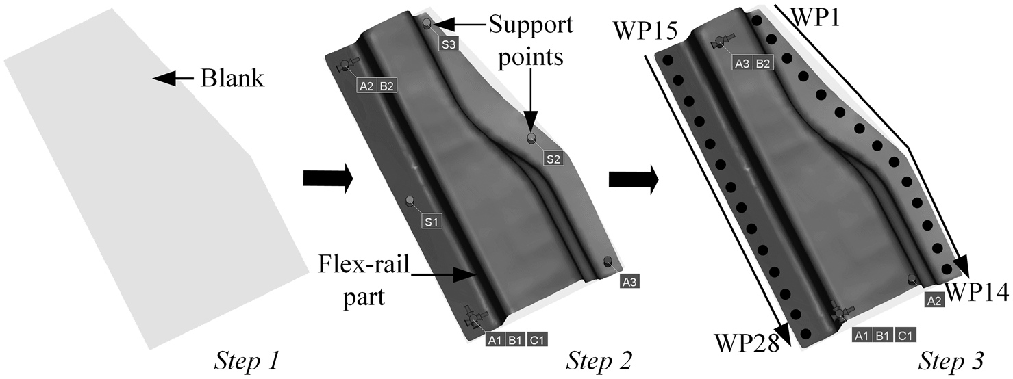
Spot welding variation simulation setup.
Results
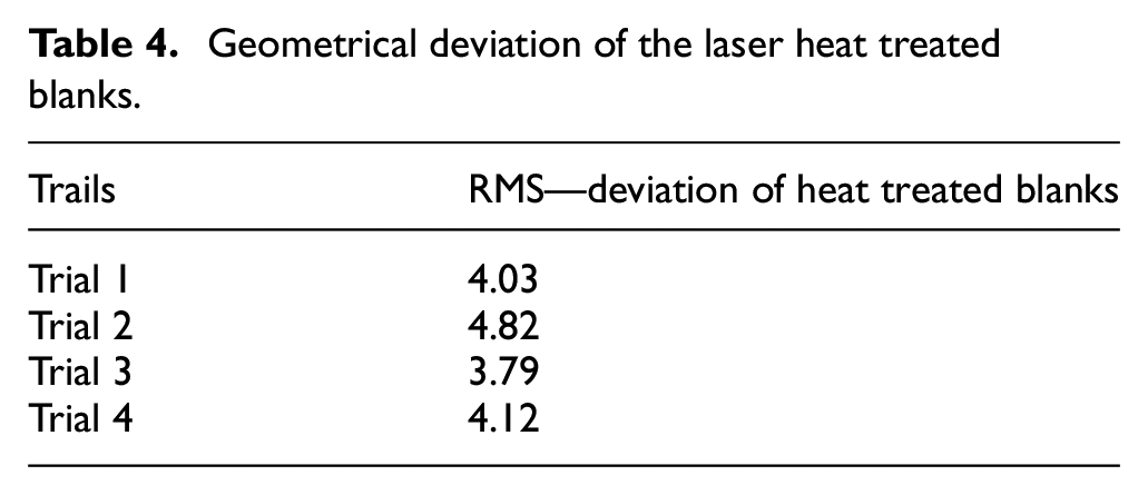
In this section, the results from the experimental study is discussed. The results are presented as per the sequence of steps explained in Figure 4. The first step was to analyze the scanned data of selectively laser heat treated blanks. The root mean square (RMS) deviation of each laser heat treated blank trial in comparison to the nominal CAD geometry of the blank is tabulated in Table 4. The RMS values listed in Table 4 represent the geometrical deviation (distortion) for each trial, obtained from RD&T simulations. Figure 11 provides the visual representation of the geometrical deviation for each trial listed in Table 4. The color coded images of each trial in Figure 11 depict the nature of geometrical deviation. The scale on the right side of each trial shows the deviation along the normal direction.
Geometrical deviation of the laser heat treated blanks.
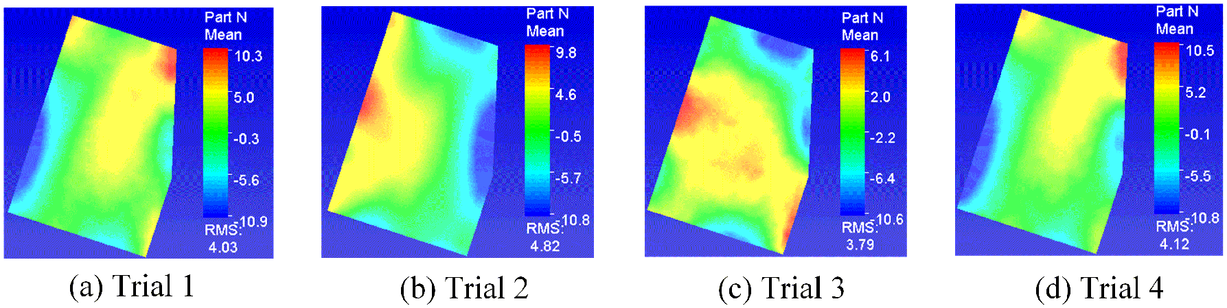
Geometrical deviation analysis of laser heat treated blanks using RD&T.
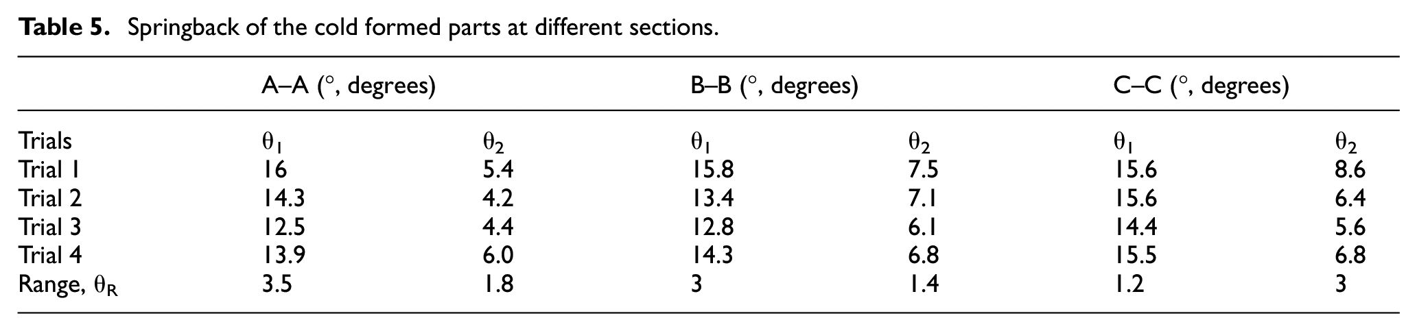
In the second step, springback of the formed flex-rail parts were assessed at three different sections as shown in Figure 12. The springback of all the trials at the defined sections are tabulated in Table 5. In the final step, spot weld variation simulation results were analyzed. Specifically, the displacement of each weld point due to springback after unclamping was assessed and is plotted in Figure 13.
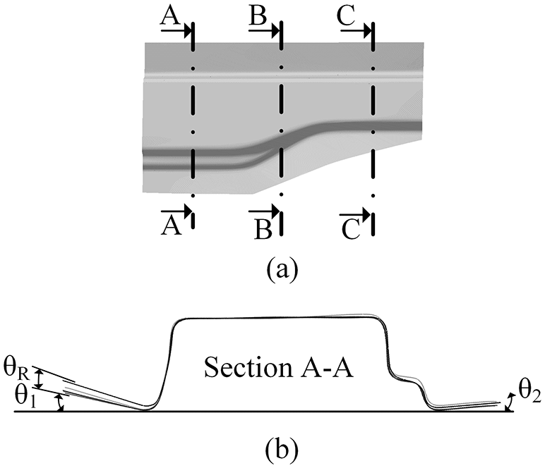
(a) Springback of the cold formed parts examined along three sections, (b) An example of Section A–A.
Springback of the cold formed parts at different sections.
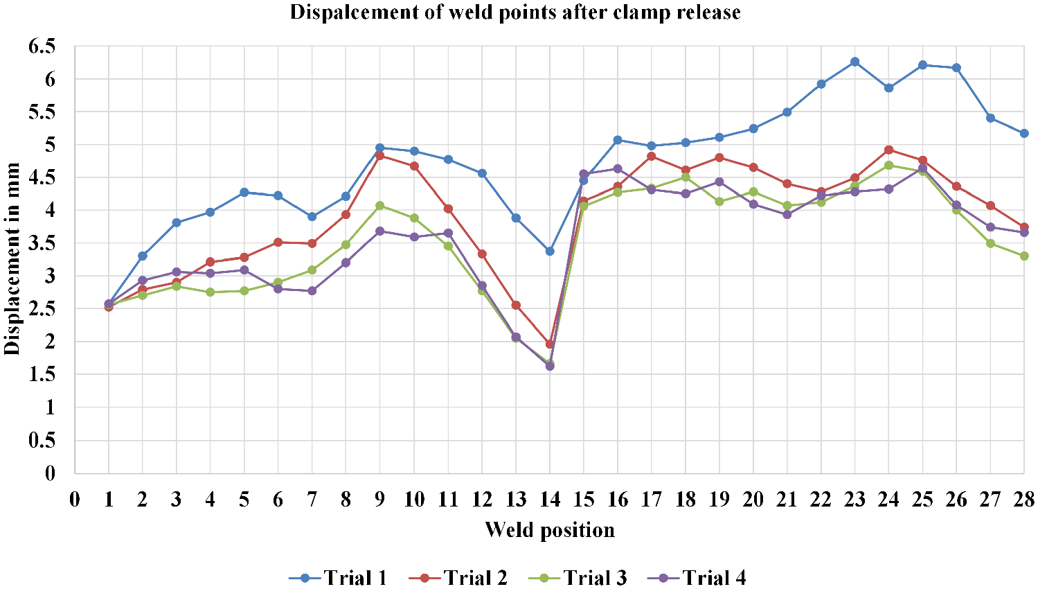
Displacement of the spot weld points after clamp release.
Discussion
In this section, the results from the previous section are discussed and the learning outcomes are presented. The RMS of geometrical deviation of heat treated blanks (Table 4) shows that there is variation in the geometry among the four trials. From the color coded images in Figure 11, it can be seen that Trial 1 and Trial 4 display similar distortion behavior in terms of shape. However, not all the heat treated blank trials reproduce similar distortion behavior as is the case with Trial 2 and Trial 3. The inconsistency in the distortion shape also prevents stackability of these laser heat treated blanks. When these distorted heat treated blanks are formed to produce flex-rail parts, the springback across the cross-sections in all the trials vary (Figure 12) as per the Table 5 data. Uneven springback along the flanges of the formed parts remain (Figure 14(a)). It is due to the carryover of distortion effect from the heat treated blank stage to the formed part stage. This highlights the effect of positioning of the heat treatment pattern or the heat treated areas closer to the edges of the blank.
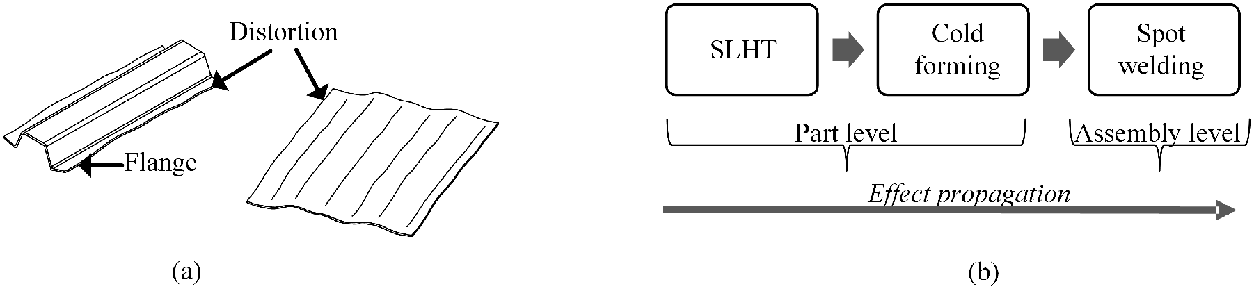
(a) Propagation of distortion from blank to cold formed part (b) SLHT process effect propagation from part level to assembly level.
This variation in springback among the flex-rail parts affects the variation at assembly level. Figure 13 summarizes the displacement of each spot weld as a result of assembly springback. In every trial, the displacement among WP 1-14 is lower than the displacement among WP 15-28. This is because the springback is much higher on θ1 side. Trial 1 which produced higher springback after forming, also produces highest assembly springback. Trial 3 which produced lower RMS deviation after laser heat treatment and lower springback after forming, produces lowest assembly springback in most of the weld points. Therefore, it can be summarized that the effect of SLHT on variation at blank level affects the subsequent processes (Figure 14(b)) as seen in flex rail parts as well as after spot weld assembly. The effect should hence be minimized at the blank level.
Based on the results, the possible sources from SLHT that should be considered to minimize the effect on geometrical variation is mapped in detail (Figure 15). They are discussed in terms of part variation, assembly variation, and design concept variation.
Since the laser process parameters such as laser power, laser scanning speed are chosen as per the required formability or strength, they are fixed and have to be adhered to. Hence, the design concept factors such as the part geometry, the corresponding locating scheme, heat treatment scan pattern, pattern positioning, heat treatment scan path sequence could be adjusted accordingly to minimize the effect on geometrical variation at blank level.
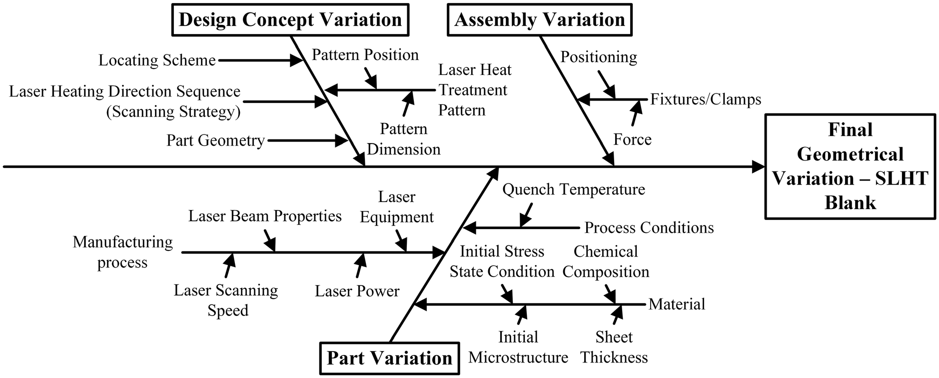
Sources of geometrical variation breakdown.
Conclusion
Selective laser heat treatment is a novel process that allows local modification of the sheet material properties to enhance formability or strength. Specifically, the method of combining selective laser heat treatment and cold forming exhibits immense potential for producing light weight-high strength components. This can aid in decreasing emissions, increase safety and provide more design freedom. While the required material modification is achieved from the selective laser heat treatment process, distortion arising is a concern as it influences the geometrical variation. It affects the functional, aesthetical aspects of the product and product’s experience for the customers.
In this work, boron steel blanks were selectively laser heat treated to investigate the effect on geometrical variation at part level as well as assembly level. A specific heat treatment pattern and laser heating direction sequence was applied. The laser heat treated blanks were then cold formed and spot welding variation simulation was performed on its 3D scanned data.
The results showed that the nature and magnitude of geometrical distortion varies among the laser heat treated blanks. Due to the dissimilarity, it prevents stackability of laser heat treated blanks. The effect propagates into the subsequent cold forming process as it influences the springback in cold formed parts. Such geometrical variation at part level leads to positioning errors when the parts are assembled to subassemblies or products. Hence, every assembled product’s quality will be dissimilar due to geometrical variation. It will affect the functional and aesthetical aspects of the product.
The effect on geometrical variation while employing selective laser heat treatment should be hence controlled at the blank level. Minimizing the effect on geometrical variation should be considered during the design phase when the concepts are being developed as the cost associated with a design change is low. It is possible to compare different concepts, and to optimize design parameters in order to increase the quality of the product. Different design concepts could be tested for sensitivity toward variation by adjusting the heat treatment patterns, pattern dimensions and their positioning, laser heating direction sequence in order to make the design more robust. Further experimental and numerical analyses are necessary to establish guidelines for robust design of selective laser heat treated sheet metal components.
Footnotes
Acknowledgements
The work was carried out at Wingquist Laboratory within the Area of Advance - Production at Chalmers University of Technology, in collaboration with VA Automotive and Swerea IVF. The support is gratefully acknowledged.
Declaration of conflicting interests
The author(s) declared no potential conflicts of interest with respect to the research, authorship, and/or publication of this article.
Funding
The author(s) disclosed receipt of the following financial support for the research, authorship, and/or publication of this article: This work was supported by the Swedish Governmental Agency for Innovation Systems (VINNOVA). The support is gratefully acknowledged.