
Abstract
This study focuses on the application of friction stir welding (FSW) process for joining of pipes. It addresses key issues associated with fusion welding techniques, such as lack of fusion, over penetration, slag inclusions, root crack, undercut root gap, and thermal distortion. The influence of process parameters on the physical properties during FSW of aluminum pipes has been studied, which allows selecting an optimum combination of parameters for achieving superior welds. Physical responses such as variation in axial force, torque, temperature, and power have been analyzed. Tensile test of the joints fabricated shows a maximum of ∼90% joint strength efficiency with respect to the base material. The peak temperature or heat input is found to be increasing during FSW, which creates a larger grain size in the stir zone of the joints, resulting in the higher hardness of the joints.
Introduction
The use of circular conduits to transport fluids is ubiquitous in the modern industrial world, for example, the transportation of crude oil from offshore oil platforms to onshore refineries, supply of domestic water from purification plant to household tap, in the delivery of coolant to heat exchangers, etc. For all these applications, different types of pipe are used based on the applications. For instance, the raw water is transported through carbon steel pipes, chemicals through stainless steel pipes, aluminum pipes for compressed air, galvanized steel pipes for drinking water, etc.1–3 These examples highlight that there is an emerging need for establishing proper installation methodology and working of these pipes.
The mechanical joining techniques for circular sections involve usage of nut, bolt, screw, thread, rivets, couplings. The use of these components for joining adds extra weight and also generates residual stresses. Majority of the pipe fabrication jobs are performed using the fusion welding techniques, which includes melting and subsequent solidification with or without the use of filler material. Defects such as lack of fusion, over penetration, slag inclusion, root crack, undercut root gap, distortions are associated with fusion welding. Further, with an increase in the thickness of the pipes to be welded, several passes are required to fill the joint, increasing the fabrication time. Friction stir welding (FSW) is a potential alternative to the fusion welding methods, as it joins the materials in their solid-state only. Several challenges, such as reduced contact area between the pipes and tool, proper alignment and fixation of the workpieces, are needed to be considered. A brief literature review on FSW of circular pipes is given in the following paragraph. These studies considered the effects of different tool rotational speed (ω) and welding speed (v) primarily.
A study varied ω from 500 to 800 rpm and v from 30 to 180 mm/min to join AA6061-T6 pipes. 4 A joint strength efficiency of 62% with respect to the base material was achieved for ω = 630 rpm and v = 60 mm/min. However, a parametric combination of ω = 800 rpm and v = 180 mm/min resulted in minimum joint strength efficiency of 13%. This is due to insufficient heat generation in the weld region. The weld with the highest tensile strength was found defect-free, while the other welds had tunnel defects. However, they did not correlate the temperature with the obtained results. Another study reported the welding of AA6063 pipes with ω ranging from 900 to 1500 rpm and v from 72 to 144 mm/min.5–7 The welded sample was characterized by joint strength and hardness. The maximum and minimum joint strength efficiency were observed to be 54% and 45% with 1500 rpm and 108 mm/min, and 900 rpm and 72 mm/min, respectively. However, the effect of process parameter on physical responses such as axial force, torque, and power has not been considered. Similarly, another group of researchers performed FSW on aluminum alloys tubes with the ω ranging from 500 to 2000 rpm and v from 100 to 400 mm/min.8,9 The maximum joint strength efficiency of 59% was achieved by employing ω = 1000 rpm and v = 200 mm/min, and the minimum of 32% with ω = 500 rpm and v = 300 mm/min. In one case, that is, at 500 rpm and 400 mm/min, the materials could not be welded due to high v and low ω. On the other hand, the maximum joint strength efficiency of 70% was achieved at ω and v of 1600 rpm and 355 mm/min, respectively. The minimum joint strength efficiency has been reported as 18% at 1400 rpm and 330 mm/min. In the above mentioned literature, the authors have covered a wide range of process parameters (ω from 500 to 2000 rpm and v from 30 to 400 mm/min).
Another challenge in the case of pipe welding is the elimination of the keyhole. This has been dealt with by using a retractable pin tool. 10 A maximum joint strength efficiency of 55% was found at 800 rpm and 50 mm/min. In another work, the researchers have utilized FSW to join dissimilar pipes 11 such as aluminum and copper. The highest joint strength achieved was 89% as compared to base aluminum. This research area was further enhanced to develop a 3D thermo-mechanical model of FSW of pipes for detailed study on temperature, strain, and material flow behavior. 12 The model has been validated with the experimental results. They have also reported that plunge depth (PD) of 0.3 mm and above provided sufficient contact between pipe and tool shoulder (25 mm of shoulder diameter) for FSW of pipe.
Prior to the welding of pipes, the FSW had been used extensively for joining plates and sheets. Few of these studies for plates welding have been discussed here. The axial force has been reported to be inversely proportional to the rotational speed of the tool, while it is directly proportional to the welding speed.13,14 The force dropped by 35% to 40% from the plunging to the welding phase. With insufficient force, wormhole or tunnel defect has been found.15,16 In another work, a series of experiments have been performed considering different ω, v, and shoulder diameter to develop a process parameter window for achieving defect-free weld. 17 They observed that the ratio of change in output responses (force, torque) to the process parameters (speed, PD) was always higher for defective weld as compared to the defect-free weld. The research was further enhanced to study the generation of residual stresses distribution in the FSW of aluminum plates by using ultrasonic waves and finite-element method.18,19 They have observed that the longitudinal residual stress occurred in the advancing side (AS). The PD played a vital role in obtaining adequate joint strength of FSW plates. Several works have reported the effect of PD on the mechanical properties of welded samples. The joint strength has been seen to be increasing with an increase in the PD.20,21 An optimum value of PD of 0.3 mm was found to produce maximum joint strength and having defect-free welds.22,23 Along with these parameters, the tool profile also plays a significant role in FSW of plates and sheets. The effect of tool pin profile on thermal cycle, material flow, mechanical and metallurgical properties of FSW samples has also been studied.24–28 The defect-free joints can be achieved using a taper and screw-threaded cylindrical pins, where the simple cylindrical pin causes kissing bonds defect. Also, the taper pin results in finest grains in the SZ, and hence the highest mechanical properties such as ultimate tensile strength, elongation, and hardness can be achieved.
It can be observed from the literature that the existing studies on pipe welding by FSW varied only the ω and v. From all these studies, the obtained joint strength efficiency lies in the range of 13% to 70%. One of the challenges in pipe welding by FSW is to ensure the proper contact between the tool and the workpiece. PD value is the indicator of the proper contact. The present study aims to widen the parametric study by considering the variation in PD along with ω, keeping v constant. A detailed analysis dealing with the evolution of axial force, torque, temperature, and power during welding has been considered. This will be helpful for a proper selection of the parameters. The importance of these aforementioned physical parameters has been reported in several research articles and thus, are necessary to be studied and explored in case of tubular structures.
Experimental procedure
Materials and methodology
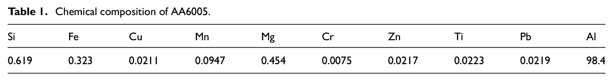
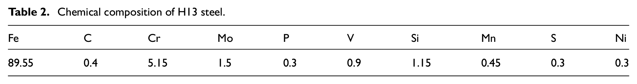
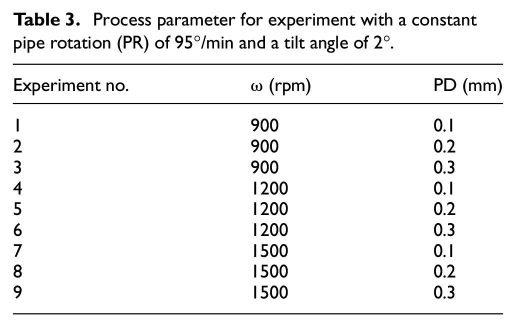
AA6005 pipes of length 145 mm, outer diameter of 60 mm, and 5 mm nominal thickness have been chosen as shown in Figure 1(a). H13 tool steel has been used to fabricate the tool with 16 mm shoulder diameter and 4.5 mm pin length. A picture of the tool is shown in Figure 1(b). The pin shape is considered as conical with 5 mm and 4 mm of upper and bottom diameter, respectively. The chemical composition of AA6005 pipes and H13 steel tool was acquired by energy-dispersive X-ray spectroscopy (EDS), and the values are listed in Tables 1 and 2, respectively. The parameters for weld fabrication are shown in Table 3. The PD refers to the penetration of the tool shoulder into the workpiece. The workpieces were cleaned by using acetone to remove the oxides and dust before experimentation.
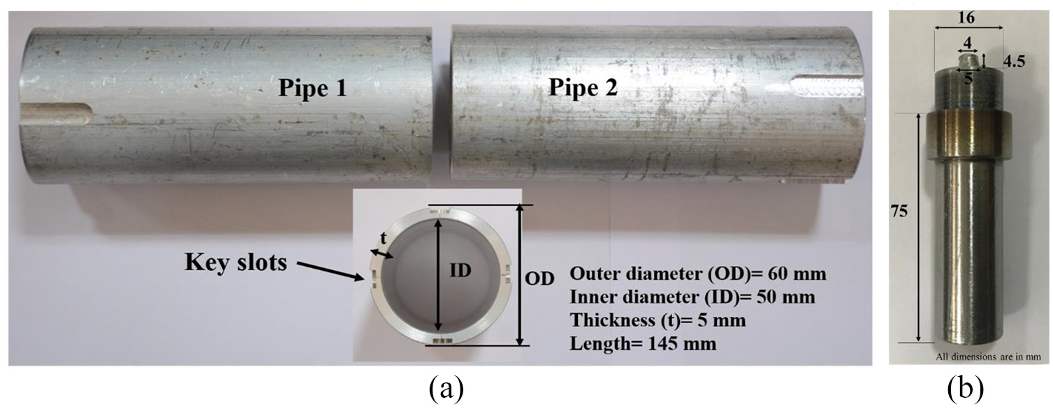
(a) AA6005 aluminum pipes (b) tool with dimension.
Chemical composition of AA6005.
Chemical composition of H13 steel.
Process parameter for experiment with a constant pipe rotation (PR) of 95°/min and a tilt angle of 2°.
Experimental procedure
The friction stir pipe welding was performed on the set of two AA6005 pipes on a six-axis FSW machine (BISS-ITW) as shown in Figure 2(a). This machine is a position-controlled one and can produce welding in a straight path, 2D planer (circular and non-circular), 3D profile, and cylindrical pipe. In the case of FSW of plates, fixing and clamping are quite easy as compared to pipes. Because of this, a fixture was used to hold the pipes accurately and rotate them uniformly at a constant speed. Figure 2 depicts the complete experimental set up along with its essential accessories.
The procedure for experimentation and the functions of the fixture are listed below:
i. Each pipe consisted of four grooves, as shown in Figure 1(a) for tightening them in the fixture.
ii. A split mandrel is passed through the pipe to avoid distortion and bending of workpieces during the welding. A schematic view of the split mandrel setup is shown in Figure 3.
iii. To support the pipes against the axial load during welding, two sets of roller bearings have been used at the bottom portion of each pipe.
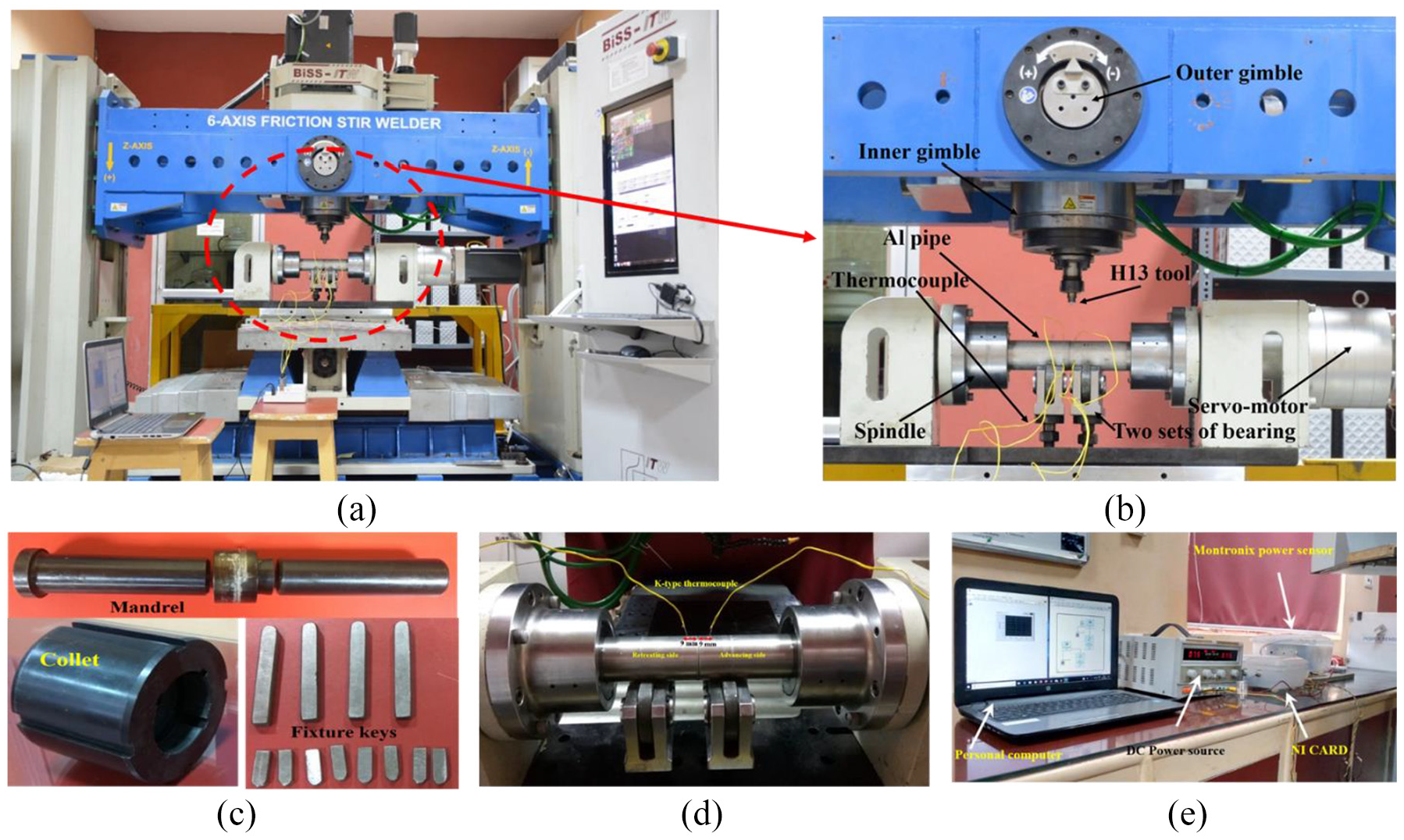
(a) Six-axis FSW machine (b) pipe welding setup (c) accessories (d) thermocouple setup (e) power sensor.
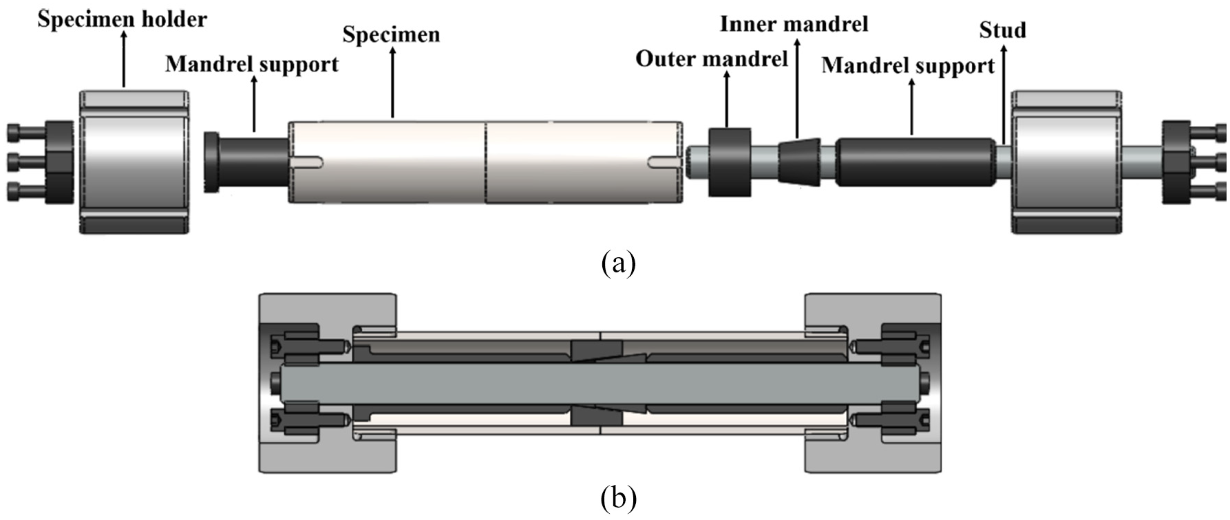
(a) Schematic view of split mandrel setup (b) cross-sectional view.
While the machine is attached with a strain gage type load cell to acquire the forces and torque, temperature, and power have been acquired externally. For temperature measurement, K-type thermocouples of wire size 0.5 mm have been used. The two thermocouples were embedded in 2 mm blind holes drilled at a distance 9 mm away from the centerline in both the sides and at 90° circumferential distance from the starting position to avoid the damage of thermocouple, as shown in Figure 2(d). A data acquisition system (NI cDAQ-9172) was used in conjunction with a data acquisition card NI-9211 and software NI-DAQ 7.3 to obtain the temperature data. Power consumption of the machine during welding was recorded by using power sensor (Montronix PS 100 AC) with DC power amplifier, as shown in Figure 2(e). For determining the tensile strength of the joints, the samples were prepared as per ASTM E8 standard. 29 The samples (as shown in Figure 8) for tensile strength were cut along the cross-section direction of the weld by Wire-cut EDM (Electra, Maxicut 523). A universal testing machine (Instron, 1344) of capacity 100 kN was used to performed tensile test at a constant cross-head speed of 1 mm/min. The defects were investigated by using macrographs and scanning electron microscope (SEM) images. To determine the hardness, Vickers micro-hardness was used.
Results and discussion
Visual inspection
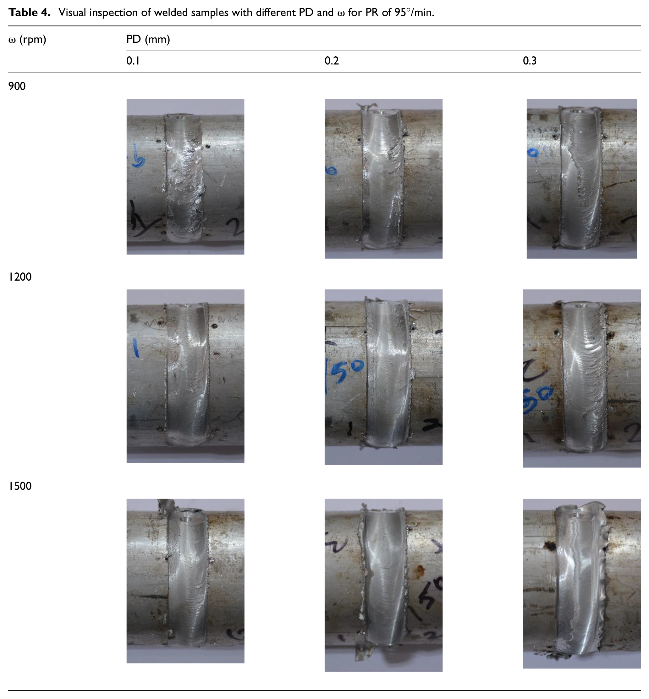
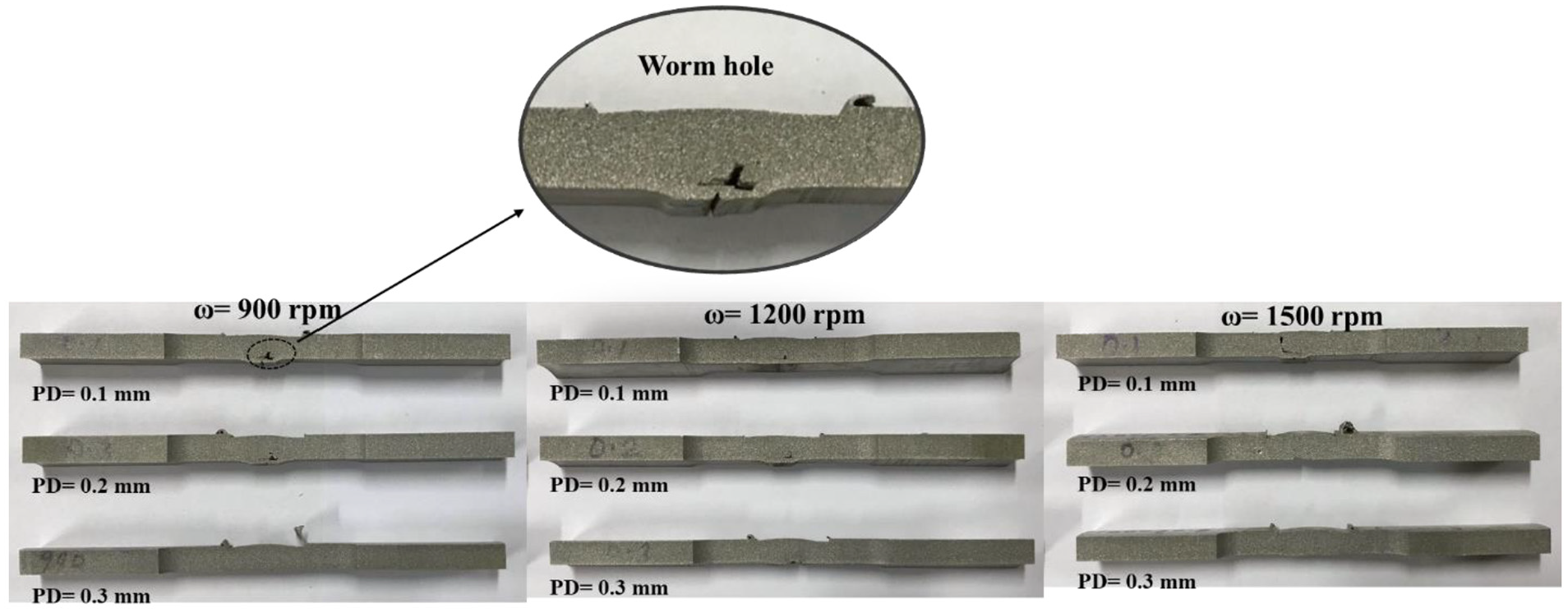
The images of welded samples with the respective process parameters are shown in Table 4. It can be observed that a smooth surface finish has been obtained with increasing ω which is due to uniform and proper stirring of material. With an increase in PD and ω, large amount of flash is also generated because of the higher amount of heat.
Visual inspection of welded samples with different PD and ω for PR of 95°/min.
Variation of axial force, torque, and power
Figure 4(a) shows the evolution of axial force (normal to the workpiece surface) during FSW. In the plot, the stages of the joining process have been depicted, where the plunging refers to the contact of the tool with workpieces to be welded. The dwelling follows the plunging stage which accounts for ensuring the plastic deformation of the workpieces to be welded. Next to this stage is the rotation of the job, that is, the pipes to be welded. 13 In this stage, the axial force represents a steady-state as compared to the other stages of the welding. Out of the three stages, the peak value is observed during initial contact of the tool, that is, at the plunging stage.
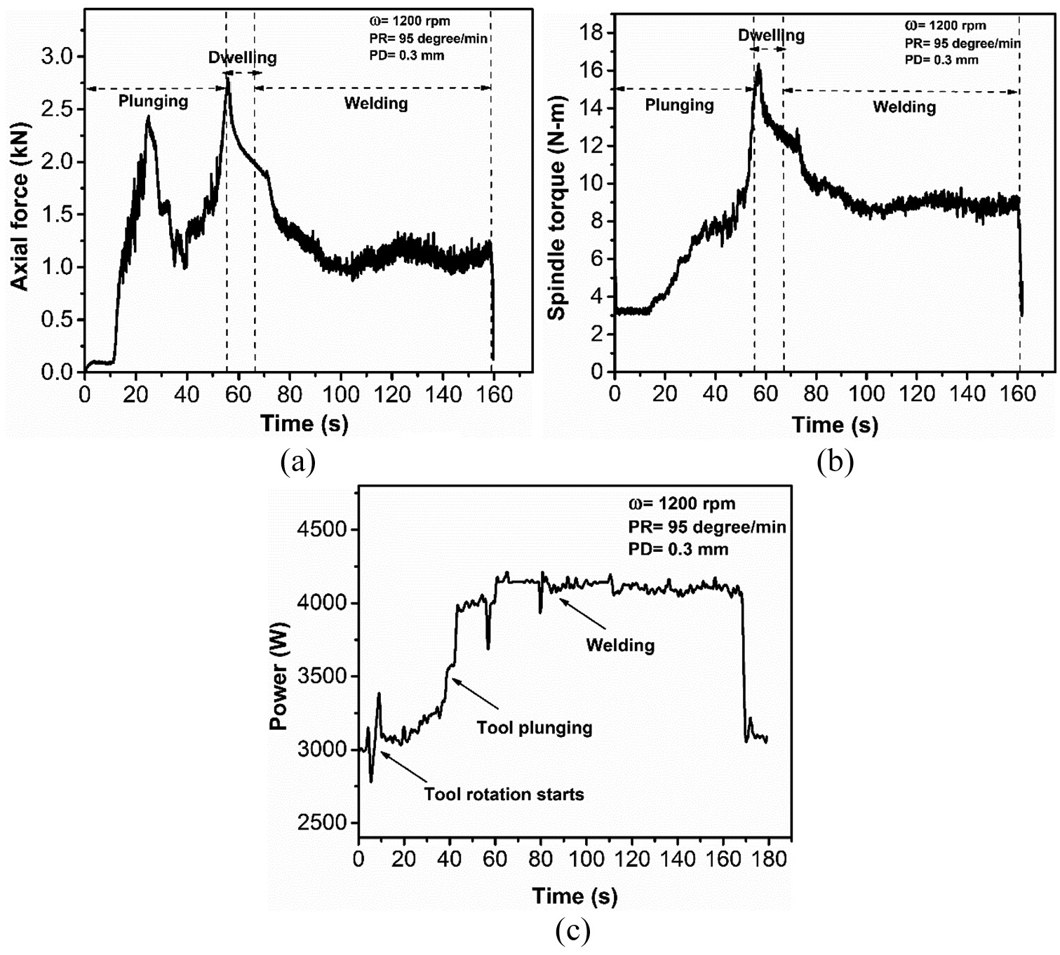
(a) Variation of axial force (b) spindle torque (c) power with time.
Similar to the above parameter, spindle torque has also been reported to be an essential physical parameter. However, unlike axial force, the spindle torque increases continuously during plunging. A gradual drop in spindle torque is seen during the dwelling phase, which is then followed by a steady value because of the start of the welding phase, as shown in Figure 4(b).
The variation of power consumption with time during welding is plotted in Figure 4(c). Here also, a steady-state region can be seen in the plot, which refers to the welding stage. The other stages have a significant variation in power consumption which accounts for the initial torque being induced in the electric motors. A comprehensive study detailing the variation of axial force, torque, and power during FSW of sheets has been presented in.30,31
Variation of temperature
The variation of temperature during welding is shown in Figure 5(a). FSW relies on plastic deformation and mechanical stirring. Here, the plastic deformation refers to the softening of the workpieces to be welded, which is achieved via a tool which is of higher strength than that of the workpieces. If the materials to be welded are not sufficiently plasticized, that is, they do not have the sufficient ductility, defective welds are formed. Thus, it is necessary to ensure that the heat available during welding is sufficient enough to soften the workpieces and take them to a stage where they can flow. The temperature generation in the process is due to the frictional heat arising from the contact between the tool and the workpieces.
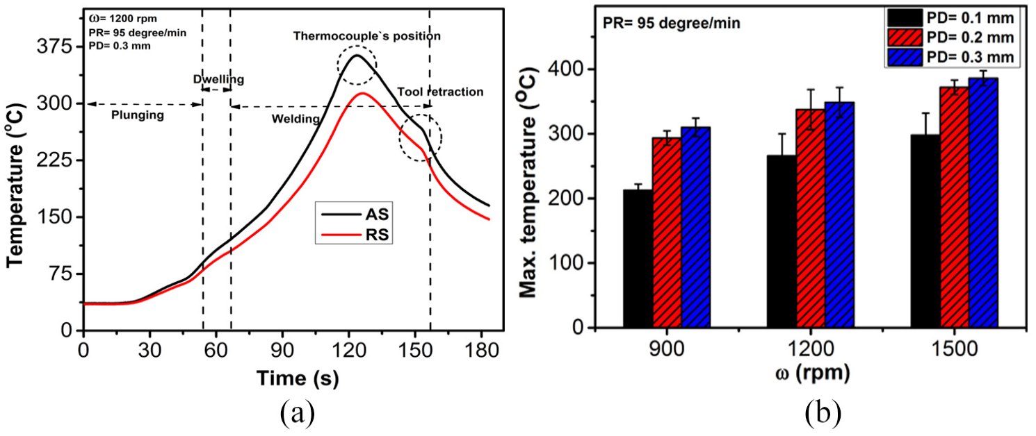
(a) Variation of temperature with time and (b) effect of PD and ω on maximum temperature during welding.
From Figure 5(a), it can be seen how the temperature rises to a peak value and then gradually decreases. The peak value of the temperature, identified by the thermocouples, corresponds to the time when the tool is closest to that point where thermocouples are engaged. Further, higher value of this peak can be seen for advancing side (AS), as compared to retreating side (RS). Figure 5(b) shows the value of maximum temperature recorded for each set of welding parameter. It can also be observed that with the increase in PD and ω, the temperature also increases. This is because of the larger area of contact, being formed with increasing PD and friction. Initially, with an increase in PD from 0.1 to 0.2 mm, the average percentage increase in maximum temperature was 30%, but afterwards, for the change of PD from 0.2 to 0.3 mm, it reduced to 4%. This is due to the thermal stabilization in the FSW process. The increase in temperature reduces the flow stress of the material, and in turn reduces the rate of heat generation due to friction and plastic deformation since both are the function of flow stress. Similar trends were observed for increasing ω from 900 to 1500 rpm (17%), and afterwards (1200 to 1500 rpm) it has reduced to 11%.
Effect of ω and PD on the average axial force, spindle torque, and power
Figure 6 shows the variation of the physical parameters (average axial force, torque, and power) with varying process parameters. It shows the decrease in average axial force with increasing ω, and an increase in the same with increasing PD. The former is because of the higher friction, which increases the deformation of the materials to be welded. On the other hand, the latter, increment in the PD, ensures larger contact surface and thus makes the average force higher. It was observed that with increase in ω from 900 to 1200 rpm, the drop in average axial force was 14%, which was due to rise in temperature. However, for the increase of ω from 1200 to 1500 rpm, it reduced to 7%, due to thermal softening. Similarly, in case of PD from 0.1 to 0.2 mm, the average percentage increase in axial force was 28%, which occurred due to larger contact area amounting high force requirement to stir the material. However, it reduced to 6.5% from 0.2 to 0.3 mm of PD because of the large amount of heat generated which led to softening of the materials.
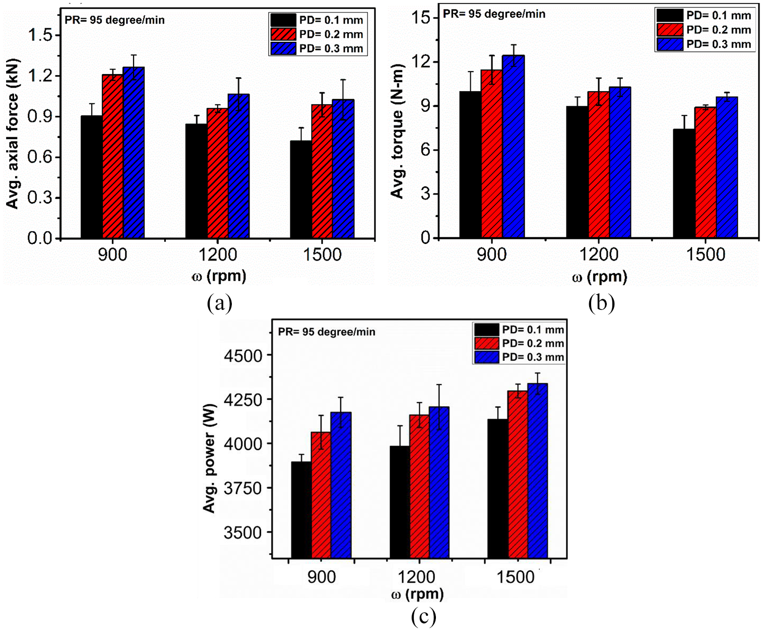
Variation of average: (a) axial force, (b) torque and (c) power plot with ω and PD.
As noted above, the frictional heat generation is more as ω increases, resulting in higher temperature and ease of material transportation during stirring. This leads to decrease in the spindle torque, as shown in Figure 6(b). In contrast, as the PD increases, the torque also increases because of the increase in axial force. The average percentage increase in torque was 15% and 6.5% for increase in PD from 0.1 to 0.2 mm and 0.2 to 0.3 mm, respectively. Also with increment in ω, the drop in average torque was 13% and 12%, respectively due to decrease in axial force, for the same increase in PD.
The consumption of power by the machine to fabricate a welded joint depends on the process parameters, tool, and type of base material. The power consumption increases with the increase in PD, due to increase in force. Also, with an increase in ω, the consumption of power increases due to the increasing rate of spindle rotation, as shown in Figure 6(c).
Defect analysis
Various welding defects have been observed in the case of FSW, which is due to the improper selection of process parameters. 32 These defects, such as lack of fill, tunnel defect, kissing bond were observed due to insufficient heat generation during the welding. 33 Moreover, due to excessive heat, some other defects were also seen, such as collapse of nugget, surface galling, etc. These defects can be largely eliminated by appropriate selection of process parameters and using real time sensor-based monitoring. 30
In the present work, defect in the weld, if any, was investigated by using macrographs and SEM images as shown in Figure 7. Tunnel defect and lack of fusion have been found due to the insufficient heat generation during welding. Weld defects were found in the welds fabricated with a PD of 0.1 and 0.2 mm. This indicates that the PD values of 0.1 and 0.2 mm lack in ensuring sufficient contact between the pipes and tool shoulder. This effect has also been seen in the joint strength of the welds. Qasim et al. 4 have also reported similar observations.
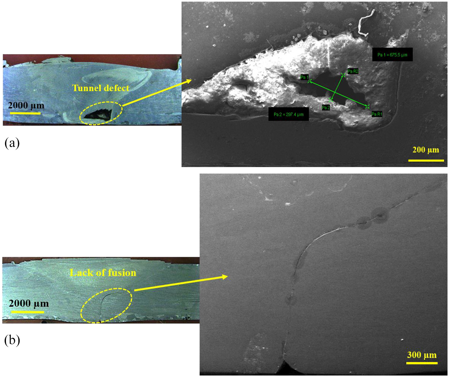
Defects occurs in FSW of pipes: (a) tunnel defect (b) lack of fusion.
Tensile test
None of the welded samples exhibited any surface defect, as shown in Table 4. Only after extracting the tensile samples from these welds, the defects could be seen. A cross-sectional view of the tensile sample of (PD of 0.1 mm and ω of 900 rpm) indicates the presence of wormhole defect, as shown in Figure 8. The variation of tensile test results for all the nine samples is shown in Figure 9. In case of samples welded with PD of 0.1 and 0.2 mm defects occurred, which lowered the joint strength. It is observed that the sample welded with PD of 0.3 mm had the highest joint strength due to the proper contact between workpiece and tool, which generated sufficient heat for welding. The maximum joint strength efficiency has been observed to be ∼90% at a ω of 1500 rpm with PD of 0.3 mm, as shown in Figure 9(d).
Cross-sectional view of tensile samples with different process parameters.
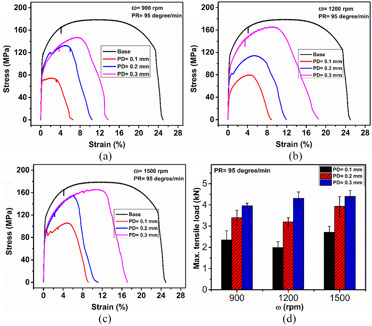
Variation of tensile load with the position at different ω (a) 900 (b) 1200 (c) 1500 rpm and (d) effect of ω and PD on maximum tensile load.
Variation of hardness
The presence of heat and deformation of the material occurring at the same time in the FSW process may be assumed as a hot deformation technique. Thus, the restoration mechanisms of discontinuous dynamic recrystallization (DDRX) and continuous dynamic recrystallization (CDRX) are common during the FSW of different metals and alloys. 34 The amount of heat input has a considerable effect on the microstructure evolution and the mechanical properties of the material during FSW. At low heat input condition, DDRX and CDRX result in the formation of fine grains, but at high heat input condition CDRX causes large grains.35,36
Four zones have been observed in FSW samples such as Stir Zone (SZ), Heat Affected Zone (HAZ), Thermo-Mechanically Affected Zone (TMAZ) and Base Material (BM).37,38 The SZ is influenced by plastic deformation, and fine grains were achieved due to dynamic recrystallization (DRX) caused by frictional heat. The region adjacent to SZ is known as TMAZ, where the grains have been elongated due to shear stresses induced by the ω. The insufficient heat and deformation in TMAZs did not create the DRX, and the grains are just deformed in these areas. 39 HAZ is present next to TMAZ; there is no plastic deformation but some variation in microstructure can be observed due to the process heat.
Figure 10(a) shows the hardness variation in the FSW sample along the weld cross-section. The profile shows “W” geometry along the plane perpendicular to the weld.12,37 The minimum value of the hardness was found at the interface between HAZ and TMAZ due to the softened region caused by the coarsening of grain during thermal cycle of the process. The maximum hardness was observed in the SZ as compared to TMAZ and HAZ due to the presence of fine grains. Figure 10(b) shows the effect of ω and PD on the average value of SZ hardness. It was observed that with an increase in ω and PD at constant PR, the peak temperature or heat input increases during FSW, which causes the formation of larger grains in the SZ. This results in the higher hardness of the joints. Similar trend had been observed in the case of plate welding.39,40
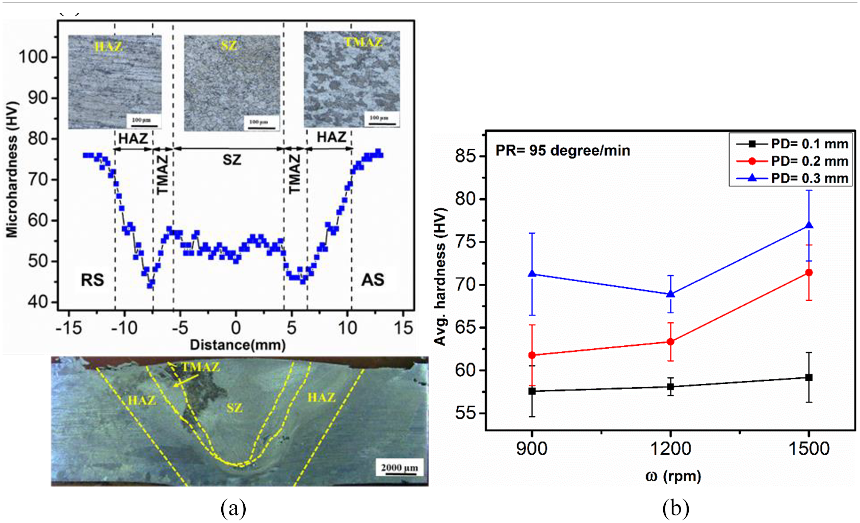
(a) Variation of hardness with different zones of the weld (b) effect of ω and PD on average SZ hardness.
Conclusion
The present article demonstrates the feasibility of using FSW as a potential technique to weld pipes. The physical responses such as axial force, torque, power, and temperature during the friction stir pipe welding have been studied for different ω and PD. Following are the conclusions from the present work:
The PD has been found to be one of the crucial parameters for achieving sound welds in case of FSW of pipes because of the tubular geometry.
The maximum joint strength efficiency has been observed to be ∼90% at a ω of 1500 rpm with PD of 0.3 mm and PR of 95°/min.
The importance of physical responses such as axial force, torque, power, and temperature have been studied for evaluating the quality of a set of parameters. Thus, they can be utilized for real-time monitoring of the quality of a welded pipe.
Footnotes
Declaration of conflicting interests
The author(s) declared no potential conflicts of interest with respect to the research, authorship, and/or publication of this article.
Funding
The author(s) received no financial support for the research, authorship, and/or publication of this article.