
Abstract
Machined components deviate in size, form, and orientation in comparison to actual features realized by the designer. The deviations originate from several process-related factors and can be specified as per the Geometric Dimensioning and Tolerancing standards (ASME Y14.5-2009 or ISO 1101:2017). According to these standards, the deviation of planar or flat components is expressed in the form of flatness error. This article presents an overall framework to estimate static deflection–induced flatness errors during end milling of thin-walled planar components. The framework incorporates the Mechanistic force model, finite element analysis–based workpiece deflection model, and particle swarm optimization–based algorithm to estimate flatness-related parameters. The individual elements of the proposed framework are implemented in the form of computational tools, and a set of experiments are conducted on thin-walled parts. It has been observed that the static deflections of the thin-walled component have considerable influence on flatness error, and the same can be captured effectively using the proposed framework. The study also investigates the effect of inevitable aspects of the thin-walled machining, such as workpiece rigidity and thinning on the flatness error. The findings of the present study aid process planners in devising appropriate machining strategies to manufacture thin-walled components within tolerances specified by the designer.
Introduction
High precision manufacturing of thin-walled components such as avionics trays and racks, jet engine impellers, turbine blades, monolithic spar-ribs, and so on is essential in aeronautical and automobile industries due to complex functional and aesthetic requirements. In recent years, computer numerical control (CNC) milling replaced metal-working and assembly operations to fabricate thin-walled components as monolithic structures. CNC milling is preferred due to its versatility to generate complex shapes in a variety of materials with high quality and productivity. Thin-walled parts are inherently flexible and prone to severe deflections under periodically varying cutting forces of the milling operation. The static deflections of components leave uncut material on the machined surface and result in the violation of tolerance.
In recent years, the designers have been employing Geometric Dimensioning and Tolerancing (GD&T) principles defined as per ASME Y14.5-2009 1 or ISO 1101:2017 2 standards to quantify the deviation of manufactured components from the desired level. GD&T offers multiple advantages to designers and manufacturers such as means for the accurate information exchange, reduction of guesswork to ensure consistent information, adaptability to digital design platforms, ensuring dimensional and tolerance requirements, increased cost-effectiveness, and so on. Geometric tolerances for components are classified as size, form, and orientation. For straight or planar elements, the size represents the fundamental dimension (length, width, or depth), while form represents flatness of the feature, and orientation signifies the inclination of a normal to the plane. The geometric tolerances are essential for manufacturers in ensuring assembly or interchangeability of components and imparting other functionality, for example, clearance for lubrication between mating parts. Based on tolerance specifications, the manufacturer is required to estimate process parameters (e.g. radial depth of cut (RDOC), axial depth of cut (ADOC), feed rate, etc.) and optimize manufacturing-related goals meeting geometric and functional aspects. Therefore, it is necessary to develop a framework that estimates the effect of process faults such as static deflections of thin-walled components, which is the primary source of flatness error.
The development of predictive models for end milling of thin-walled components has been an active research area for several years, and multiple attempts are reported in the literature. The research attempts can be divided into three categories: development of cutting force models; prediction of process faults, for example, tool-workpiece deflections, vibrations, surface error, and so on; and compensation or error control models. The cutting force models are essential for the analysis of end milling operation without conducting rigorous experimentation. The cutting force models presented in the literature can be categorized into four broad groups: experimental models, 3 mechanics-based analytical models, 4 data-driven models, 5 and Mechanistic model. 6 Among these, the Mechanistic model is popular as it does not require analytical formulations related to the complex milling mechanics. The approach correlates cutting forces with uncut chip area determined geometrically using Mechanistic constants. 6 The model has matured over the years by incorporating effects of various process characteristics such as size effects, 7 cutting edges, 8 cutter run-out, 9 and so on. It can be inferred that the Mechanistic model can predict cutting forces with reasonable accuracy over a wide range of cutting conditions. The present study implements the Mechanistic force model to predict cutting forces during milling of thin-walled components.
The literature also reports different models for the prediction of surface error due to static and dynamic deflection of thin-walled components. The majority of research attempts involve the application of finite element analysis (FEA)-based algorithms for estimating workpiece deflections. These models differ based on the type of elements used, methods of meshing,10,11 state of clamping, the nature of cutting force application, 12 and so on. The methodology to estimate workpiece deflection–induced surface error evolved with systematic approaches such as enabling direct transfer of cutting forces from Mechanistic model to FEA 13 and incorporation of workpiece rigidity change with the progress of machining14,15 were presented in the literature. Obeidat and Raman 16 estimated workpiece deflections during end milling of flat plates to determine the location of the maximum error, thereby optimizing the number of inspection points required to determine the flatness. Bera et al. 17 estimated tool-workpiece deflections to analyze the variation of surface error during milling of thin-walled tubular geometries. Arora et al. 18 used FEA-based methodology to link axial surface error profiles with cutting depths during end milling of thin-walled components. The FEA-based approach was extended to analyze the effect of component thickness, cutting temperature, 19 tool inclination angle, 20 and other process parameters on workpiece deflections during milling of thin-walled components. The studies inferred that the three-dimensional (3D) FEA model is critical to analyze cutter workpiece interactions during end milling of thin-walled parts. The present study devices FEA-based methodology integrated with Mechanistic force model to estimate coordinates representing the deformed machined surface due to workpiece deflections.
The flatness error of the planar component is defined as the normal distance between two parallel planes enclosing deformed coordinates representing the machined surface. The previous studies estimated flatness error with a focus on the development of efficient and reliable algorithms. Shunmugam 21 proposed the concept of deriving the median plane as a reference from the point-cloud data to estimate crest and valley points. Traband et al. 22 developed a convex hull technique to enclose the point-cloud data and determined the minimum zone for flatness. Samuel and Shunmugam 23 proposed divide-conquer and merger technique to construct two-dimensional (2D) and 3D convex hull for evaluation of the flatness. Murthy and Abdin 24 summarized numerical methods such as least-square fitting, Monte-Carlo approach, simplex search, spiral search, and so on in the determination of flatness error. Among these, least-square fitting is commonly employed for the evaluation of flatness error due to lesser computational complexity. It was observed that the method accords the unique solution for flatness, but it does not conform to the minimum zone deviation. 25 An algorithm based on Chebyshev approximation was subsequently presented to estimate the minimum normal distance between two parallel planes. Liu et al. 26 developed a hybrid approach comprising genetic algorithm and geometric characterization to evaluate straightness and flatness. Kovvur et al. 27 used the genetic algorithm–based methodology in the form of particle swarm optimization (PSO) to evaluate flatness error. It was highlighted that the PSO algorithm could estimate flatness error efficiently, offering ease of computational implementation in comparison to other techniques presented in the literature. Pathak et al. 28 presented a modified version of PSO to overcome inefficiencies, such as computation time and iterations required to obtain the optimum solution. Recently, some studies have been done to examine the effect of machining attributes on the flatness error. Sheth and George 29 used statistical techniques to evaluate the significance of process parameters on surface roughness and flatness during the face milling operation. Mikó and Rácz 30 studied the effect of surface roughness on flatness and angularity during the ball-end milling operation.
The review of the literature presented above indicated that the studies related to static deflections of thin-walled components primarily focus on the estimation and influence of process parameters on the surface error. The quality of the machined surface is not only expressed using surface error or roughness parameters but also dictated using dimensional and geometric tolerances. It is demonstrated in the previous studies that the evaluation of surface or form error is entirely different from flatness values. 30 The research attempts considering the assessment of flatness are limited to algorithm development based on the point-cloud data acquired using coordinate measuring machine (CMM) with no relation to process faults such as workpiece deflections in the case of thin-walled geometries. The prediction of flatness error is crucial for process planners in selecting appropriate cutting conditions to limit it within an acceptable range with components meeting functional requirements in an assembly. However, there has been no attempt reported in the literature that correlates process faults, for example, static workpiece deflections with flatness error. The present article attempts to bridge this gap by developing a framework that correlates static workpiece deflections with the flatness error during end milling of thin-walled components. The study further investigates the importance of inherent attributes such as thinning of the component and workpiece rigidity on the flatness error. Henceforth, the article is organized as follows: sections “Modeling of deflected machined surface” and “Flatness error evaluation” present the overall framework to estimate distorted coordinates representing machined surface and flatness error with its associated parameters. Section “Computational and experimental results” summarizes computational and experimental results to examine the efficacy of the proposed framework. The article concludes with a summary of conclusions drawn from the present work in section “Conclusion.”
Modeling of deflected machined surface
The determination of flatness error during end milling of thin-walled components requires the computation of deflected coordinates representing the machined feature. The overall framework necessitates systematic computational procedure incorporating end milling process physics through cutting force model, workpiece deflection model, and mechanism to transform deflections into deformed coordinates representing the machined surface. The Mechanistic cutting force model is employed in this study to estimate cutting forces during end milling operation. 8 The static deflections of thin-walled components due to machining forces are estimated using FEA-based workpiece deflection model. The deflection data are transformed subsequently into deformed coordinates representing the machined surface.
Mechanistic force model
The Mechanistic model estimates cutting forces for end milling operation by discretizing an end mill into a finite number of disk elements having an equal thickness
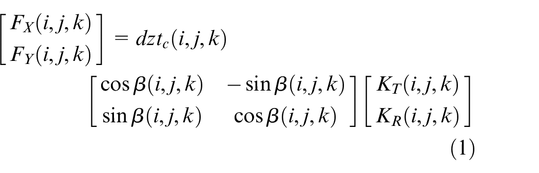

The terms

Workpiece deflection model
The instantaneous cutting force components predicted using the Mechanistic model outlined in the previous section are input to the 3D FEA model to estimate static deflections of thin-walled components. A 3D FEA model is necessary to predict static deflections of thin-walled components as workpiece rigidity diminishes significantly with the progress of machining due to component thickness reduction. The component geometry is modeled using ANSYS Parametric Design Language (APDL) environment to predict deflected coordinates representing the machined surface. The meshed model of the component is shown in Figure 1(a). A 3D 8-node solid-shell element (SOLSH 190) has been used to ensure the advantages of using solid elements and its ability to avoid shear locking. 31
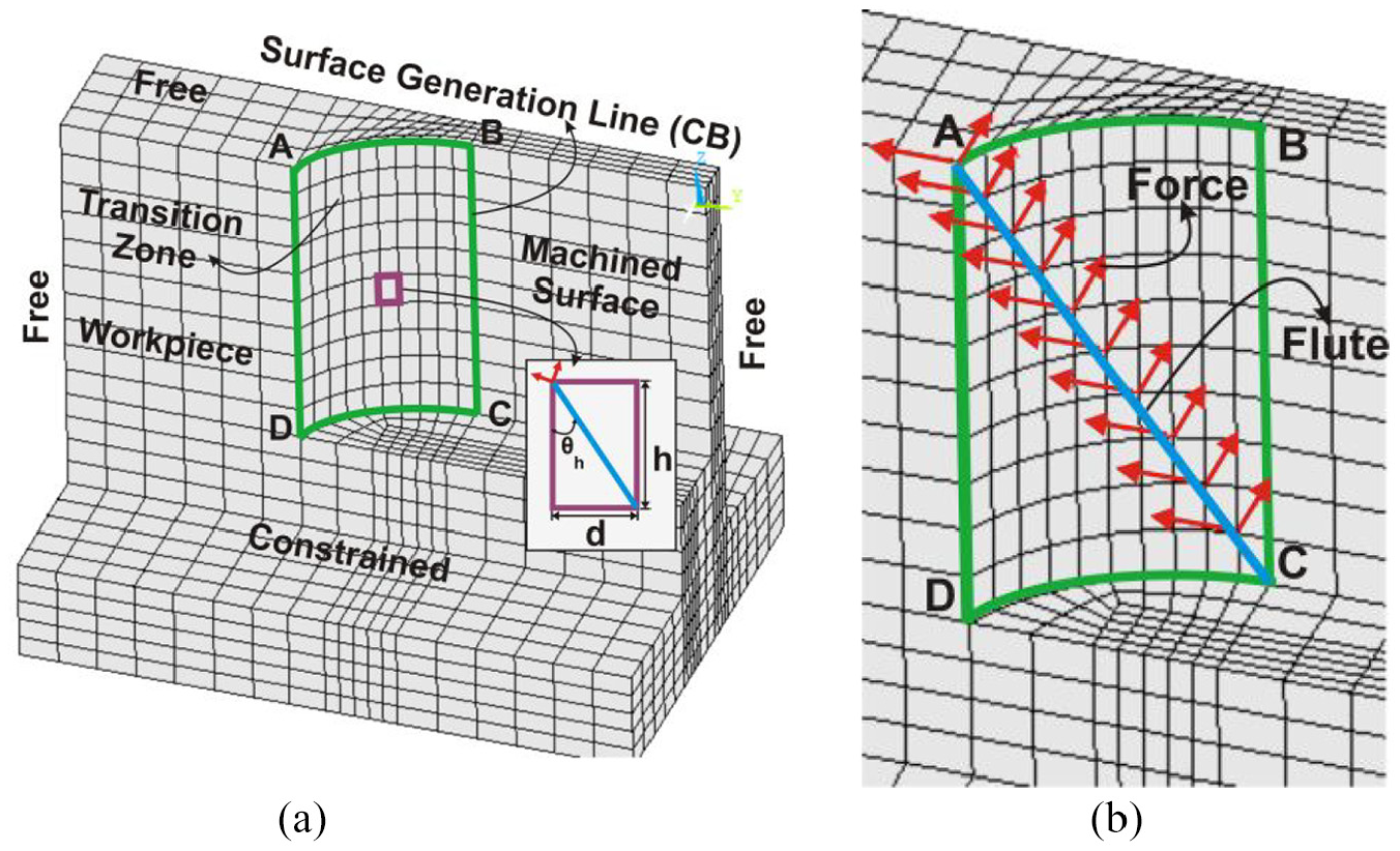
FEA model of thin-walled component: (a) meshed component; (b) application of cutting force.
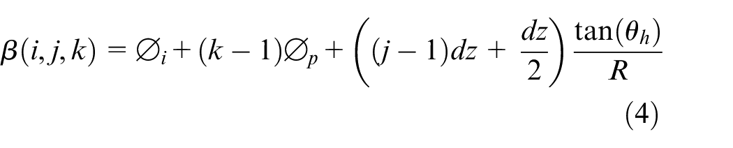
The thin-walled component is modeled and analyzed considering the free–free–free–clamped condition (Figure 1(a)), that is, it is free to deflect along the top, right, and left ends, but it is constrained from the bottom end. The tool-workpiece interaction area at any instant is termed as the transition zone, which is shown as ABCD in Figure 1(a). The flute enters the transition zone through vertex D along edge DA while it exits through edge CB with vertex B traversed last. The cutting force components act along the flank edge of the tool inclined at the helix angle. Three-dimensional 8-node solid-shell elements with height
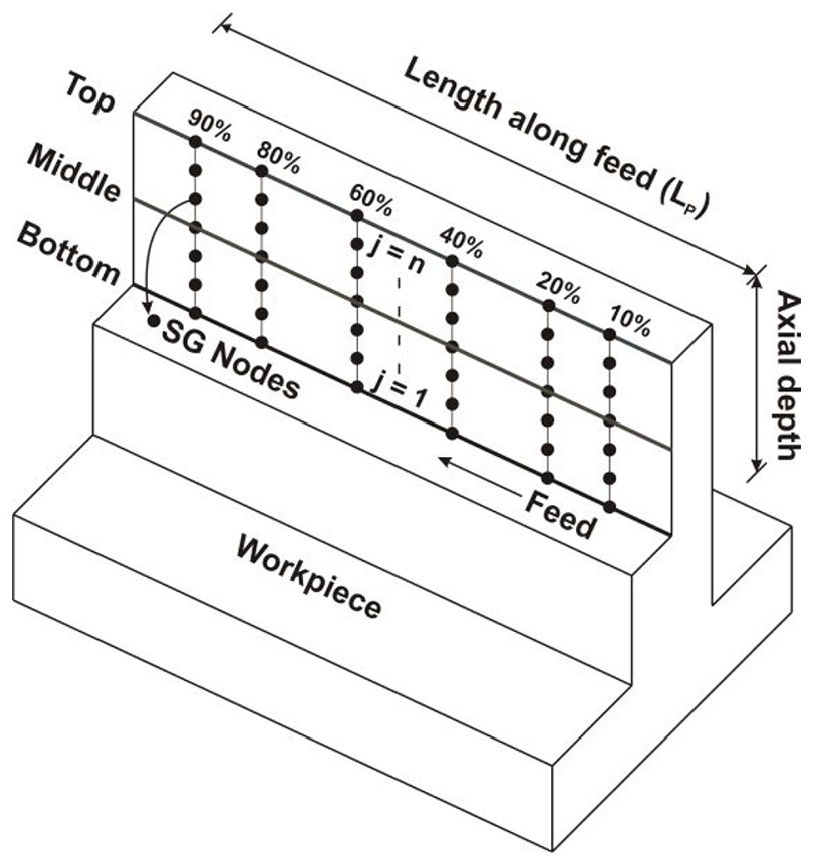
The recording of deflection at each node in the transition zone is not essential as surface generation (SG) occurs only when a flute passes through the exit edge CB. The exit edge CB is termed as SG line, and corresponding nodes lying on the edge CB are termed as SG nodes. The deflection of SG nodes needs to be recorded to estimate distorted coordinates representing the machined surface. It is required to evaluate cutting forces and apply them to the revised FEA model of the component to estimate workpiece deflections at each incremental rotation of the cutter. These steps are repeated at each SG instant until deflection is computed for each node on edge CB. Once deflection values are computed, it has to be transformed in the form of coordinates representing the distorted machined surface. The subsequent section summarizes the methodology to accomplish the task of obtaining deflected coordinates.
Estimation of deflected coordinates
The thin-walled components are inherently flexible and deflect easily under the application of cutting forces. The material removal during end milling operation reduces component rigidity further and increases the flexibility as well as static deflections along the feed direction. It necessitates estimation of static deflections at different locations
Locations for assessment of workpiece rigidity effects.
The deflection data estimated using programmed RDOC can be used to estimate corrected RDOC

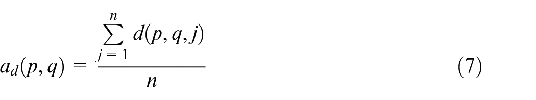

It is necessary to transform static deflections of thin-walled components in the form of the point-cloud data representing distorted coordinates to estimate flatness error. The transformation necessitates synchronization of the Cartesian coordinate system before machining and coordinate system in which deflections are computed using the FEA model. After synchronization, the deflection value

Computational framework for determination of deflected machined surface.
Flatness error evaluation
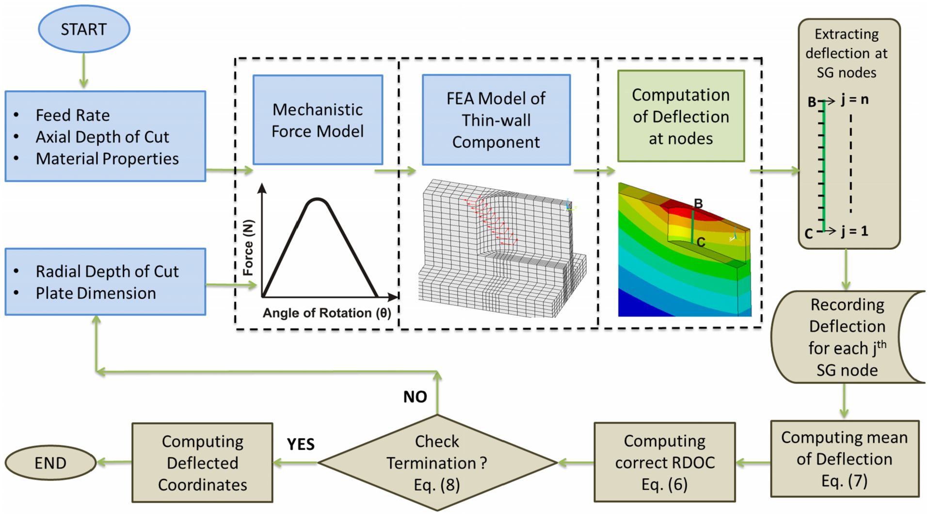
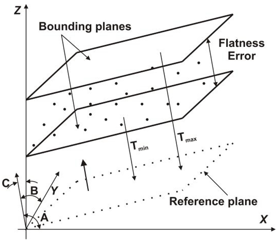
Flatness error is defined as the orthogonal distance between the two parallel bounding planes encompassing distorted point-cloud representing the machined feature. Figure 4 shows a simplified diagram highlighting features used in the estimation of the flatness error. The present study employs a PSO-based numerical technique for the estimation of flatness. Eberhart and Kennedy 32 developed the PSO technique, which has been employed in multiple applications owing to ease of computational implementation with the requirement of conditioning fewer parameters compared to the other algorithms. It provides an accurate solution with faster convergence in many cases, and it is preferred for the non-linear optimization problems. 33
Representation of flatness error.
Formulation of objective function
The derivation of objective function depends on the feature reference parameters from which the minimum normal distance between the nearest and farthest point is optimized. The reference for determination of flatness is a planar feature which can be mathematically expressed using equation (10). The coordinates representing the distorted thin-walled machined surface
The algorithm requires evaluation of independent parameters, namely, direction angles


Algorithm implementation
This section summarizes the implementation of PSO algorithm in determining flatness parameters for distorted coordinate data obtained using computational models outlined in the previous section. The particles

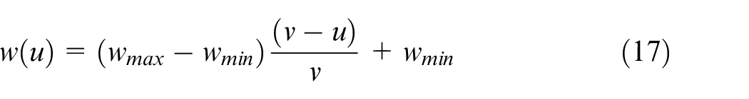
The effectiveness of the PSO algorithm in determining global minima depends on specific attributes such as the number of particles in a swarm, their initial position, inertia weight, and acceleration coefficients. If the particles are too less, the algorithm may not investigate solutions space
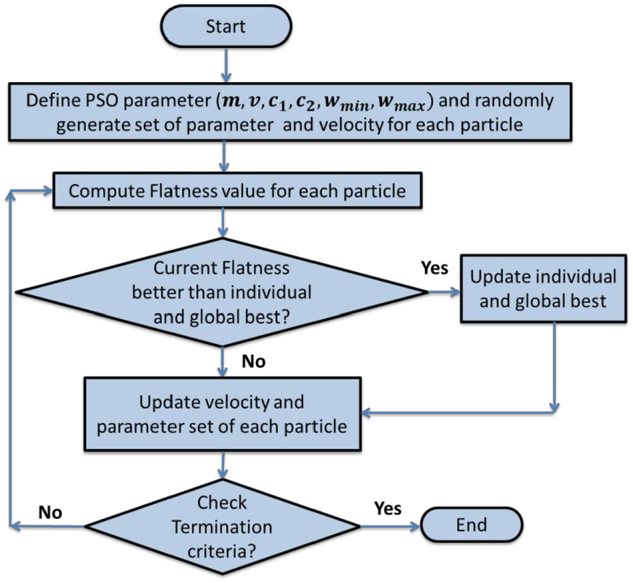
Computational framework for determination of geometric error using PSO.
Computational and experimental results
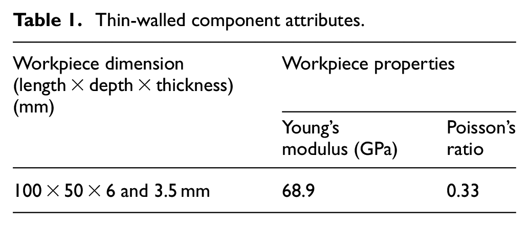
A set of mathematical models discussed in the previous sections are implemented in the form of computational programs to estimate deflected machined surface coordinates and flatness parameters using MATLAB® and APDL platform. The machining experiments were conducted using a three-axis CNC vertical milling machine for different cutting conditions of thin-walled components, as depicted in Figure 6(a). The workpiece material is Aluminum 6061-T6, with Table 1 summarizing attributes related to the down-milling of the thin-walled component. A solid carbide flat end mill of relatively larger diameter was clamped in a rigid tool holder with short overhang to minimize the effect of tool deflections on results. Table 2 summarizes process parameters and other cutting conditions used during machining experiments to substantiate the proposed methodology. A spindle mounted inspection probe (Renishaw OMP-400) is used to obtain distorted coordinates representing the machined surface, as shown in Figure 6(b).
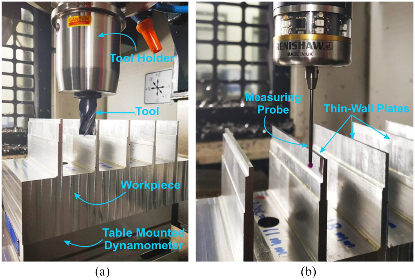
Experimental setups for machining of thin-walled components: (a) machining setup; (b) measurement setup.
Thin-walled component attributes.
Machining conditions.
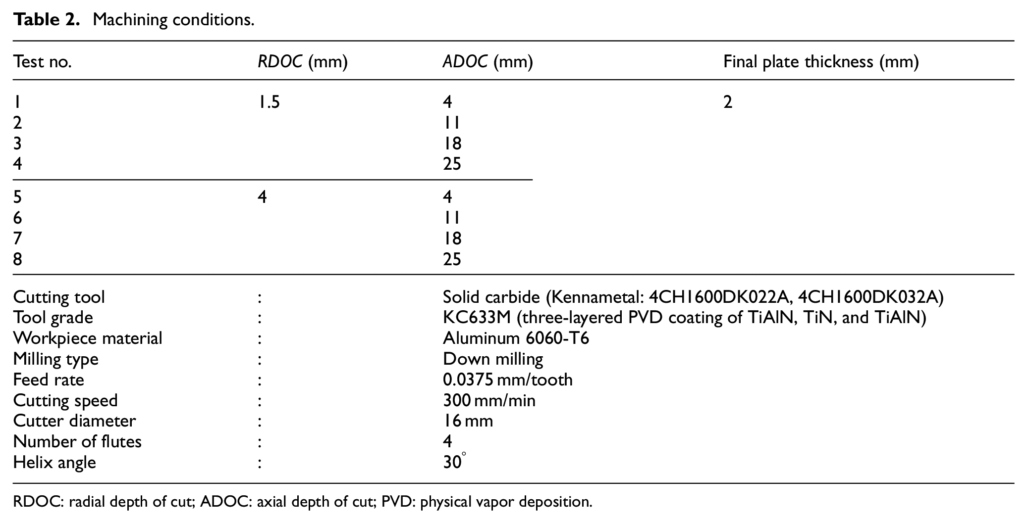
RDOC: radial depth of cut; ADOC: axial depth of cut; PVD: physical vapor deposition.
Assessment of flatness error
A series of computational studies and machining experiments are performed over a wide range of conditions to examine the effectiveness of the proposed framework in estimating flatness error during milling of thin-walled components. The final thickness of thin-walled components is kept identical during each experiment for the consistency and comparison of the results. The RDOC, ADOC, and starting plate thickness were varied to examine the effect of component rigidity on flatness error. The coordinates representing deformed surface are obtained computationally and experimentally at 10- and 1-mm interval along the length of the component and ADOC, respectively. The coordinates are input to the PSO-based flatness error determination algorithm.
Figure 7 shows a comparison of flatness error and associated parameters obtained computationally along with experimental results for cutting conditions corresponding to Test 1. It can be seen that the experimentally measured flatness values are slightly higher than the computational values. The same can be attributed to the higher contribution of tool deflection in comparison to other Tests 2–4 at similar RDOC. The computational model presented in this article considers end mill as a rigid body mounted in the tool holder and does not incorporate the effect of tool deflection. However, the tool is prone to deflections under the application of cutting force during the machining of thin-walled geometries. The higher contribution of tool deflection can be attributed to better rigidity of the thin-walled components at lower ADOC and lesser material being removed. It can be concluded that the contribution of tool deflection is significant at lower values of ADOC. The observation can be substantiated further using results corresponding to Test 5 (Table 3), where the deviation is considerably higher due to elevated cutting parameters, thereby increased cutting forces.
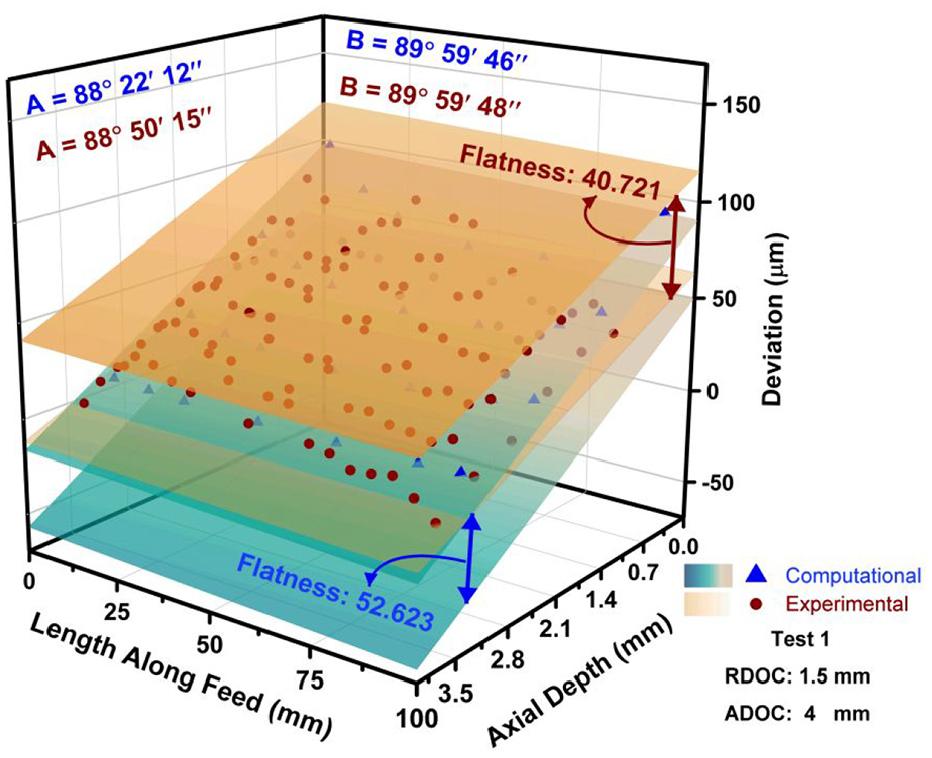
Assessment of flatness error (Test 1).
Computational and experimental flatness values.
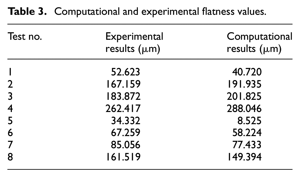
Figure 8 shows the comparison of flatness error and associated parameters obtained using computational models and machining experiments for conditions corresponding to Test 3. These test conditions represent process parameters at elevated levels, thereby significantly higher cutting forces than Test 1. The workpiece rigidity reduces significantly in this case due to the higher amount of material being removed with the progress of machining, resulting in considerable workpiece deflections in comparison to the other cases. It can be seen that the computational values of flatness error agree well with the experimental measurements. Table 3 summarizes the comparison of flatness error determined through computational approach and machining experiments for all cases. It is evident from the results that the flatness values estimated using the computational model are in good agreement with experimentally measured values for most cases.
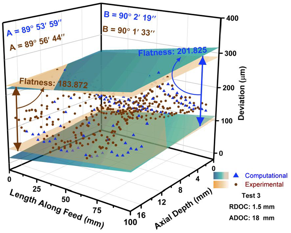
Assessment of flatness error (Test 3).
Effect of workpiece thinning
The rigidity of the thin-walled components reduces considerably with the progress of machining, resulting in increased deflections toward the end of the cut. The rigidity reduction of the component with the progress of cut is termed as thinning in the literature. The distorted machined coordinates are estimated computationally and experimentally at different locations along the feed direction
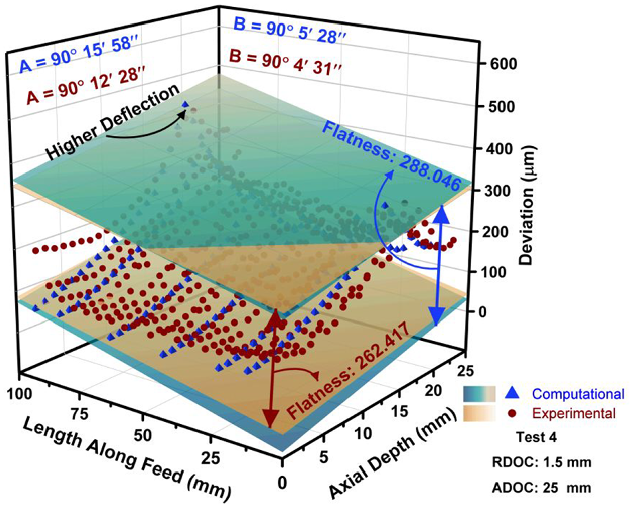
Effect of thinning on flatness error (Test 4).
Effect of initial workpiece thickness
The initial thickness of the workpiece is a decisive factor governing rigidity and thereby static deflections for thin-walled components. The components having identical final thickness but different rigidity under unmachined state are analyzed further to investigate the effect of this aspect on flatness error. It resulted in different values of RDOC during the cut as the final thickness to be achieved after the single-pass finishing is identical. Figure 10 depicts the variation in the flatness error with an increase in the unmachined thickness of the component. The unmachined thickness is varied from 3.5 to 6 mm, followed by a change of RDOC from 1.5 to 4 mm to achieve the identical thickness after machining for each case. The increase in unmachined thickness enhances workpiece rigidity, but larger RDOC leads to elevated cutting forces during the machining operation. It can be seen that the combination of the large initial thickness of the component and higher RDOC can reduce flatness error considerably. It has been reported in the literature that the higher RDOC increases cutting forces considerably due to elevated metal removal rates. The increased cutting forces contribute to static deflections of the component, but the same is not reported for the flatness error. It can be seen from Figure 10 that the flatness error is smaller at higher RDOC, which can be attributed to enhanced rigidity of the initial component. This aspect was substantiated further by conducting machining experiments at two conditions Tests 2 and 6 (Table 2). Figure 11 shows the comparison of flatness error determined using computational models and machining experiments. It can be concluded that the rigidity of the unmachined thin-walled component can be a critical parameter in controlling flatness error for the process planners.
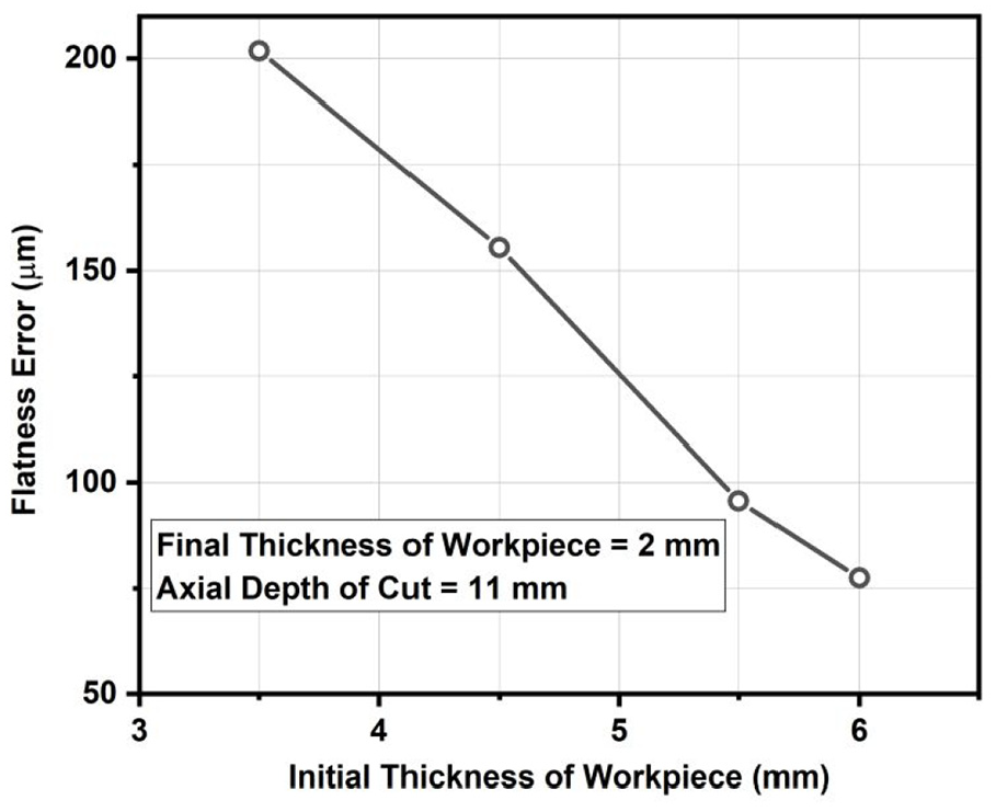
Variation of flatness error with initial thickness of the workpiece.
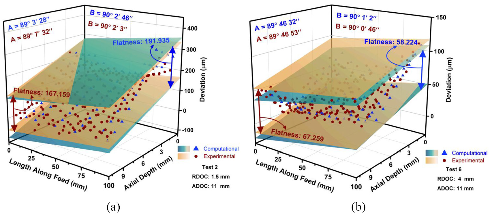
Effect of initial thickness on flatness error: (a) Test 2; (b) Test 6.
Conclusion
This article presented a comprehensive framework to estimate flatness error resulting due to process faults such as static deflections of thin-walled components during the end milling operation. The major conclusions drawn from the present work can be summarized as follows:
The computational framework presented in this study can estimate flatness parameters, that is, flatness error and angle of inclination of bounding planes accurately and effectively during milling of thin-walled components. The computational results obtained using the proposed framework are in good agreement with end milling experiments.
The thinning of the component with the progress of milling operation has a marked effect on static deflections and flatness error. The increased static deflections result in widely spread distorted coordinates and increased flatness error. But, there is a negligible change in the angle of inclination. The information related to flatness error parameters can be useful for process planners in devising an appropriate strategy to minimize flatness error.
It is also realized that the flatness error is dependent on the unmachined state of the thin-walled component. The larger thickness of the unmachined component enhances the rigidity remarkably, thereby reducing workpiece deflections, although cutting forces are higher. An optimum combination of unmachined thickness and cutting forces can be used effectively by process planners in controlling flatness error during end milling of thin-walled components.
Footnotes
Declaration of conflicting interests
The author(s) declared no potential conflicts of interest with respect to the research, authorship, and/or publication of this article.
Funding
The author(s) disclosed receipt of the following financial support for the research, authorship, and/or publication of this article: The authors thank the Department of Science and Technology-Science and Engineering Research Board (DST-SERB) (Project No: YSS/2015/000495) and Ministry of Human Resource Development (MHRD), India, to provide financial support to carry out this research work.