
Abstract
In this study, a rapid manufacturing process based on the combination of polymer three-dimensional printing and pressureless loose sintering was explored for the fabrication of complex shape electric discharge machining pure copper electrodes with the cryogenic cooling channel. The fabricated electrodes were used to perform electric discharge machining on D2 steel workpiece. The comparative study was performed on material removal and electrode wear rates between the solid copper electrode, rapid manufactured electrode without cryogenic cooling and with cryogenic cooling. Also, the surface characteristics of the worn electrode and the machined workpiece were studied with and without cryogenic cooling. The significant effect of the cryogenic cooling on the electrode wear rate and the surface roughness was observed. Better surface finish, small cracks and less debris were notified on the workpiece surface machined with rapid manufactured electrode with cryogenic cooling due to rapid dissipation of the heat from the surface of the electrode after machining. Similarly, few cracks and low carbon deposition was observed on the rapid manufactured electrode with cryogenic cooling surface after machining as compared to rapid manufactured electrode without cryogenic cooling. The sharp corner edges of the complex shape tool in rapid manufactured electrode with cryogenic cooling were retained after machining due to low melting and vaporization of the electrode material. The dimensional deviation of the machined surface with respect to computer-aided design model was compared. The rapid manufactured electrode with cryogenic cooling was found to machine the more accurate complex shape features in terms of dimensions on the workpiece as compared to rapid manufactured electrode without cryogenic cooling.
Keywords
Introduction
In the current era, non-conventional machining processes have been utilized for manufacturing precise dimensions, smooth surfaces and controlled metallurgical conditions. 1 Among various non-conventional machining processes, electrical discharge machining (EDM) is the most practised and experimented process that can satisfy a broad range of engineering applications. 2 The significant performance responses in EDM process are material removal rate (MRR), and electrode wear rates (EWRs) and surface roughness (SR). Despite all the advantages of EDM, attempts have been made on improving the MRR with improved surface finish and low EWR. Noticeably, EWR is the most important problems in the EDM process that influences the re-predictability of desirable geometrical characteristics of the electrode on the workpiece. 3 Different variants or assistance such as ultrasonic vibration, cryogenic cooling, magnetic field, air/gas and so on have been explored by several researchers for the improvement in EWR in EDM.4–7
The cryogenic cooling method has shown in its ability to improve the machining characteristic from many years. The liquid nitrogen (LN2) is the most commonly used cryogenics owing to its widespread availability worldwide. Cryogenic machining aids in altering the material properties of the tools and workpiece materials and significantly contributes to the dissipation of the heat generated at the cutting zone. 8 Therefore, the cryogenic cooling during machining gives advantage such as high productivity, better surface finish, longer tool life, environmentally safer, healthier for the workers and so on. 9 Two different methods have explored cryogenic cooling assistance in EDM. In first, the electrode and workpiece were treated with the cryogenic liquid for the different time before EDM. On the other side, channels were fabricated directly in the electrode, and the cryogenic liquid was passed through the channel during EDM. Rahul et al. 10 analysed the surface integrity and metallurgical characteristics of the machined Inconel 825 workpiece utilizing cryogenically treated electrode in contrast to the non-treated electrode. The treatment of the tool material with cryogenic not only helps in controlling the wear of the electrode, but also improves shape retention capabilities, fatigue life, thermal properties and limits coefficient of friction. Kumar et al. 5 investigated the effect of cryogenic treatment on the wear rate of the copper–tungsten electrode for the EDM of Ti-5Al-2.5Sn alloy. The quick removal of the heat from the surface due to cryogenic treatment reduced the EWR by 15.86% and resulted in a few cracks on the cryogenically treated electrode after machining. Kumar and Kumar 11 investigated the machining of aluminium-based metal matrix composite with conventional EDM process as well as cryogenic cooled EDM process with cooling channels. The electrode wear was found to drop by 18%, and improvement in the SR was observed from range 17%–29% after cryogenic cooling. Indeed, it must be due to the uniform distribution of the temperature in case of the cryogenically treated tool. 12 Hui et al. 13 examined the discharge characteristics employing cryogenically cooled electrode EDM in distilled water as dielectric and revealed that the discharge gap was smaller than conventional EDM. Kumar and Kumar 14 investigated the EDM machining of ANSI D2 steel with an electrode having cryogenic cooling channels. The results depicted reduction in EWR by 20%.
Furthermore, the percentage of carbon was efficiently reduced with cryogenic cooling of the electrode. Srivastava and Pandey 15 performed machining of M2 grade high-speed steel with EDM process with cryogenically cooling channels copper electrode. The comparison between EWR, MRR and SR was acquired with and without cryogenically cooled electrode. SR and EWR were determined to be lower with the cryogenic process as compared to conventional EDM through MRR were better with conventional EDM process. The shape of the electrode and surface integrity of workpiece machined with the cryogenic process has been observed to be better as compared to conventional EDM process. Goyal et al. 16 evaluated the outcome of cryogenically assisted electrode discharge machining (CEDM) process using cryogenically treated and cryogenically untreated AISI D2 tool steel workpiece. A reduction in tool wear rate (TWR) and SR by 26% and 11% was observed using cryogenic treatment.
Complex shape electrodes are required to machine hard materials by EDM to obtain complex shape cavity, which has shown a significant requirement for the complex shape die design industry. In recent times, rapid manufacturing (RM) has been taken into consideration for the fabrication of complex shape EDM electrodes. Various metal RM techniques, for instance, selective laser sintering/melting (SLS/M), direct metal laser sintering (DMLS), laser engineering net shaping (LENS) and so on can be used for fabrication of complex shapes.17–19
Tang et al. 20 utilized LENS machine for the fabrication of the EDM electrodes. Different composites were fabricated by mixing copper with nickel, tungsten and boron carbide to increase the feasibility of the copper electrode fabrications. The developed electrodes resulted in poor replication of electrode shape on the workpiece and also possessed low materials removal and high EWR as compared to pure copper. Dürr et al. 21 explored the fabrication of copper alloy electrode with SLS technology. The fabricated electrodes resulted in low accuracy of the machined surface as compared to the solid copper. Amorim et al. 22 fabricated four different types of electrodes like pure copper, bronze–nickel, copper–bronze–nickel and steel alloy using SLS. However, the EDM performance using fabricated electrodes was reduced as compared to the solid copper electrode. Czelusniak et al. 23 used copper nickel–titanium/zirconium boride composite electrodes fabricated by SLS for the EDM process. The electrodes resulted in low EWR as compared to solid copper. Also, the SR of the machined surface improved as compared to machined by solid copper. However, these direct RM processes are highly costly and are difficult to constitute the pure copper complex shape components. 24
On the contrary, indirect RM techniques including the combination of three-dimensional (3D) printing technique such as stereolithography (SLA) and fused deposition modelling (FDM) with other conventional methods such as casting, sintering, electroplating, spraying of metal as rapid tooling has been noted for the fabrication of complex shapes.25,26 The procedure implemented is economical and convenient for the manufacturing of complex shapes and a diverse range of materials. Dimla et al. 25 demonstrated the practicality of fabricating complex shape copper electrodes by electroplating copper on the SLA polymer model. The variability in the thickness of copper was observed to be a big concern, and electrodes failed to machine the workpiece efficiently. Yang and Leu 27 experienced similar results on the EDM of complex shapes using SLA, and electroforming fabricated electrodes. The large dimensional deviation from the computer-aided design (CAD) model was observed in the machined cavity. Rennie et al. 28 examined the EDM process using electroforming on the SLA printed complex shape to fabricate copper electrodes. The deposition of copper was found non-uniformly, and the electrode failed to machine on the corners and edges. Gillot et al. 29 explored the combination of 3D printing and electroplating for the fabrication of copper electrode for the EDM process. The shape of the fabricated electrode was found to be similar to the CAD model. However, the dimension deviations on the machined cavity were observed to be substantial, and electrodes wear rate was too high as compared to solid copper electrodes. Anil and Çoǧun 30 explored the EDM electrode fabrication coating copper using electrolysis on SLA printed part with and without cooling channels. The cooling water was used to cool down the electrode during EDM. The cooling during EDM increased the machining depth by 10%–15% as compared by without cooling during EDM. However, the copper coating ruptured easily, and the electrode was highly damaged after the EDM. Sometimes, due to low glass transition temperature of SLA polymer, fabricated electrodes also burn out after the EDM.
The other approaches of indirect methods applying 3D printing and pressureless sintering were also analysed for the fabrication of pure copper 3D complex shapes. Bai and Williams 31 revealed binder jetting and conventional sintering process to explore the fabrication of pure copper complex parts. However, the fabricated parts reported high volume shrinkage (greater than 23%) and high porosity due to void created by evaporation of binders. 32 The combination of polymer extrusion process and sintering was also identified for the formation of pure copper parts. 33 However, the involvement of oxidation and chlorides as impurities, high shrinkage and porosity was reported for the fabricated parts. The investigations were made using the assistance of ultrasonic vibration for decreasing the porosity and improving the density of the pure copper parts made by utilizing 3D printing and ultrasonic-assisted sintering.34–36 The fabricated part of pure copper complex shapes resulted in low porosity but challenging to fabricate large size parts as per the shape and size requirements of EDM electrodes. 37 Singh and Pandey 38 have recently investigated a rapid tooling method of fabricated pure copper electrodes with polymer 3D printing and pressureless loose sintering. The optimization of the sintering parameters was performed to achieve maximum density, electrical conductivity and minimum volumetric shrinkage. The proficiency of the approach was shown by fabricating multiple shape electrodes and EDM over the D2 steel. However, the process resulted in low MRR and high EWR. Singh et al. 39 also optimized the EDM parameters namely pulse duration, pulse current and duty cycle using rapid manufactured complex shape solid copper electrode by polymer 3D printing and pressureless sintering to minimize the EWR, dimensional deviation of the machined cavity as compared to CAD model of the electrode and to maximize the MRR.
From the literature review, cryogenic cooling assistance in the EDM has shown a significant effect to improve the life of the tool in terms of reduction in EWR and the surface characteristics of the machined workpiece. Also, the indirect RM process–based combination of polymer 3D printing and pressureless sintering has shown the ability to fabricate complex shape EDM pure copper electrode. However, high EWR was found during EDM. Therefore, the present study focused on to fabricate complex shape pure copper solid electrode with cryogenic cooling channels by the polymer 3D printing and pressureless sintering. The performance on the basis of EWR, MRR, worn electrode and machined surface characteristics and cavity’s dimensional deviation was performed and compared between the solid copper, rapid manufactured electrode without cryogenic cooling (RME) and with cryogenic cooling (RMECC).
Materials and method
Materials
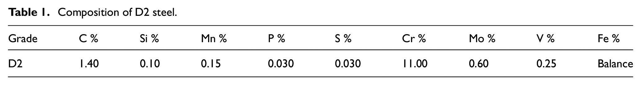
Spherical shape–based copper powder (procured from MEPCO, India) was used for the fabrication of copper electrode with the varying particle size of 3–55 µm. Investment powder from Bego-Bellasun, Germany, was procured for the mould preparation. D2 steel workpiece with dimensions 100 × 100 × 15 mm was used for the EDM, and the composition of the purchased steel is given in Table 1.
Composition of D2 steel.
RM of electrode with cooling channels and EDM setup
The procedure for the fabrication of the copper electrodes with cooling channels is given in Figure 1 (Patent application no. 201811019951). First, the CAD model of the EDM electrode with the required shape was designed in SolidWorks 2014. Later, the file was converted into STL (tessellation) file, and slicing was done with 0.1-mm layer thickness for the printing purpose. The sliced model was 3D printed using polymer material–based castable resin by SLA-based 3D printing machine (Formlabs, USA). The printed polymer model was cleaned using acetone and later used as a pattern for the mould preparation. The polymer pattern was fixed in an open plastic box, and investment powder mixed with hardener was poured on the pattern. The hardened mould was positioned in the furnace for heating and evaporation of the polymer pattern at 700 °C for 1 h. The copper pipe was bent in a particular shape (ref. Figure 1) according to the EDM tool size to ensure cooling uniformly. The emery paper was used for the surface finishing of the pipe and cleaned by acid pickling. Later, the pipe was placed inside the obtained mould cavity. The copper powder was poured in the cavity along with the copper pipe and settled using the mechanical vibrations. The filled cavity with copper powder and pipe was placed inside the tube furnace for the sintering. The sintering was performed at 335 °C/h heating rate with 782 °C sintering temperature and 62-min soaking time. The sintering cycle was optimized using multi-objective optimization for the maximum density, electrical conductivity and minimum volumetric shrinkage in the previous study by Singh and Pandey. 38 The sintered sample possessed 7.12-g/cm3 density, 40.98-MS/m electrical conductivity and 7.35% volumetric shrinkage. The post-processing procedure of shot blasting and acetone cleaning was performed on the sintered EDM tool. The in-depth discussion of the process was given elsewhere.38,39
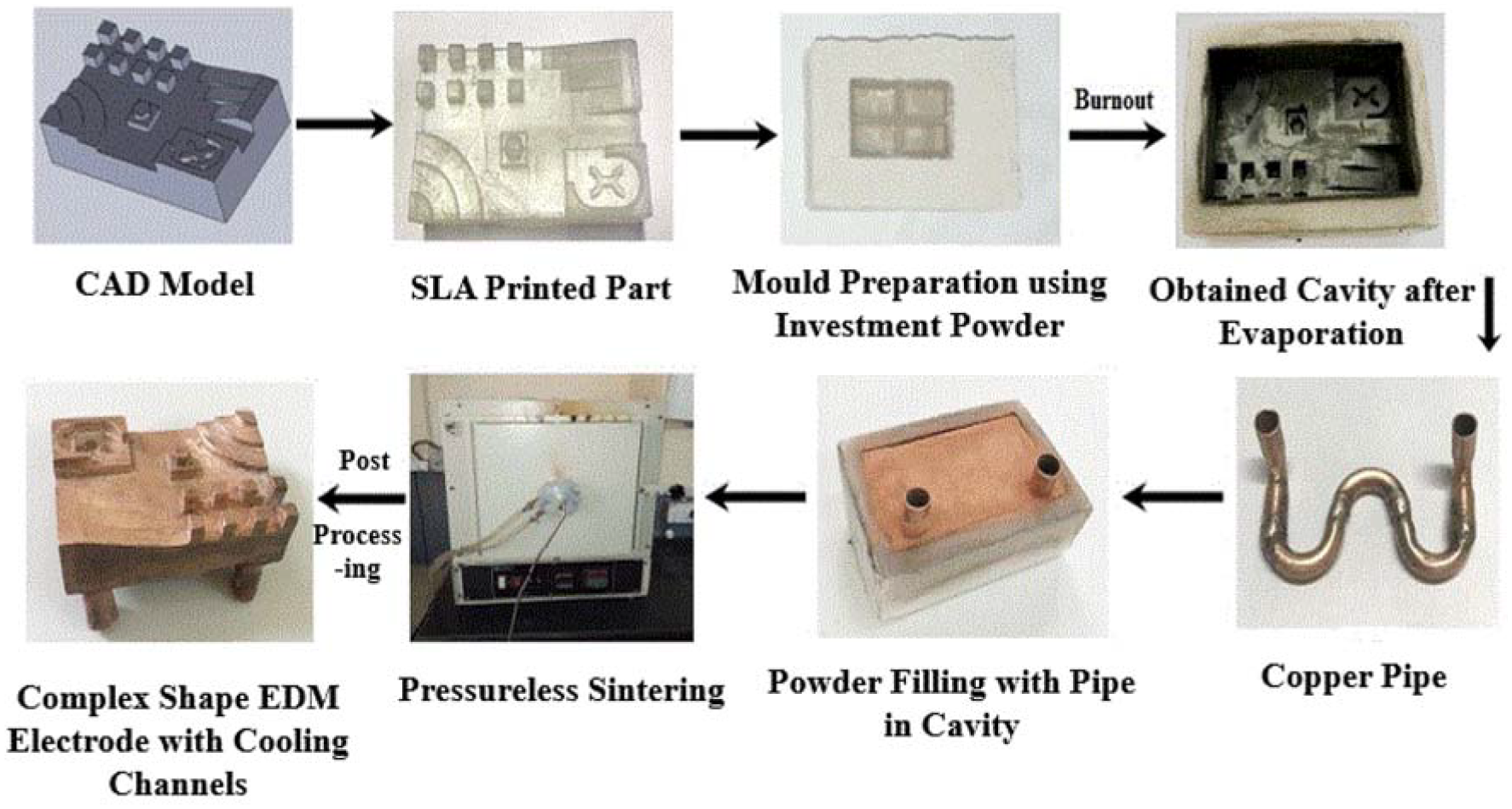
Flow chart for the rapid manufacturing of copper electrodes with the cooling channel.
For the present study, two different types of EDM electrode cross-section shapes with cooling channels were fabricated by the developed RM method. These are rectangular shape with 58 × 36 mm2 tool one with a flat face and other with complex shape tool having different features. The CAD models and dimensions of the shapes are shown in Figure 2.
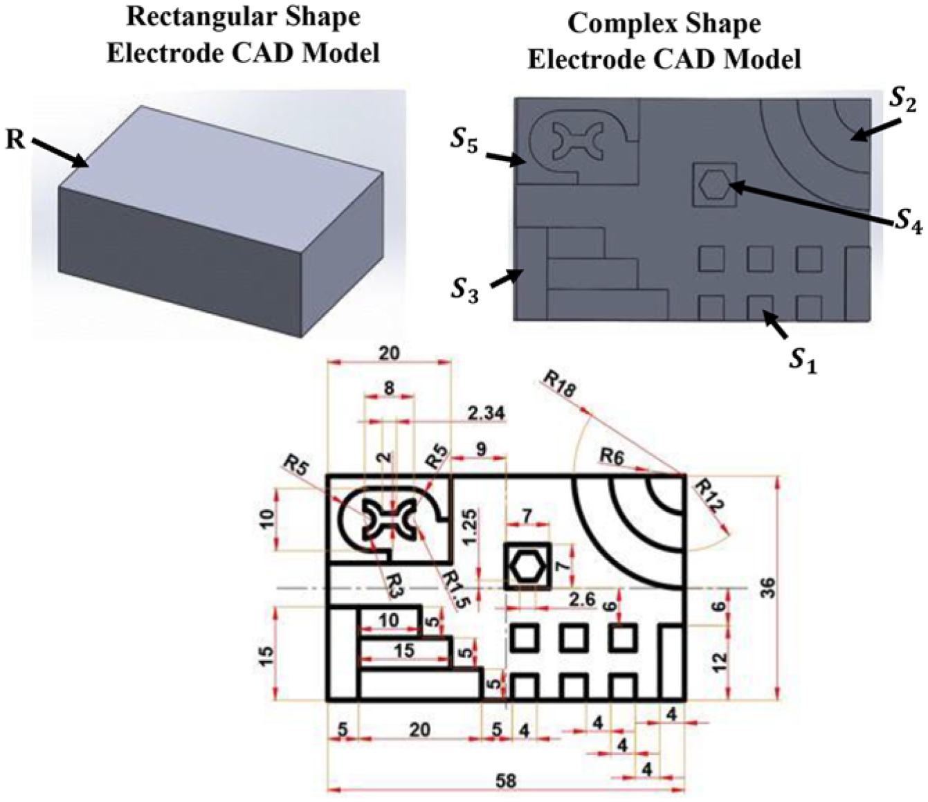
CAD model and drawing of the EDM tool.
Furthermore, the rapid manufactured electrodes with cryogenic channels were utilized for the EDM of the D2 steel workpiece. The machining was performed on the conventional EDM machine procured from Savita machine tools (model no. ZNC EDM-3250). The setup arrangement with the cryogenic cooling assistance EDM using RMECC is shown in Figure 3. The fabricated electrode was brazed with a copper rod and secured to the machine head. The workpiece was held in the jaws of the vice. The cryogenic liquid (LN2)-based Cryofab™ Dewar was used to store the liquid nitrogen. The flexible pipe–based arrangement was used for the flow of cryogenic liquid from the cylinder to the cooling channel in the electrode. The first end of the copper pipe channel was attached to the outflow of the cryogenic liquid Dewar. The other end of the pipe was open to release the liquid nitrogen in the air. A constant flow of the liquid was maintained for the cooling of the electrode. A k-type thermocouple (0.1 °C least count) was used for the measurement of the electrode temperature during EDM. The 5-mm depth hole was drilled on the edge of fabricated electrode opposite to inlet of pipe, and thermocouple was placed inside the hole. The EDM was performed at the optimized machining parameter (pulse duration = 391 µs, duty cycle = 75% and peak current = 6 A). The parameters were optimized using design of experiments approach and genetic multi-objective optimization algorithm for the maximization of MRR and minimization of EWR and dimension deviation of the EDM cavity from CAD model by rapid manufactured solid copper electrode in the previous study by Singh et al. 39
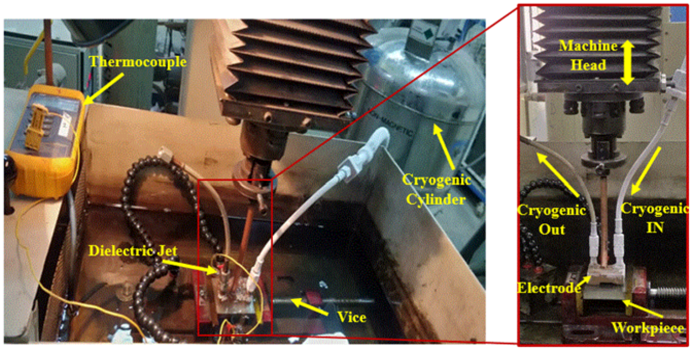
Cryogenic EDM setup.
Characterizations
The RMECC was cut from the wire EDM for the observations of the cross-section view. For the microscopic analysis of the sintered electrode, the sample was polished by silicon carbide polishing paper with up to 2000-grit size along with alumina and nano-diamond paste on a velvet cloth for the mirror-image surface. After polishing, samples were ultrasonicated and cleaned with distilled water. Finally, the mirror-polished samples were etched for 5 sec with using 25-g iron (III) chloride, 25-mL HCL and 100-mL distilled water solution as per ASTM E407-07. The etched sample was observed under the optical microscope.
The MRR and EWR were measured as the workpiece material removed and electrode material loss per unit time of the EDM. The weight of the fabricated electrode and workpiece was assessed before and after the EDM using the electronic balance to obtain MRR and EWR. The morphology of the machined workpiece and worn electrode was observed using the scanning emission microscopy (SEM) (Zeiss EVO 60) along with energy dispersive X-ray (EDX) analysis of the worn electrodes. The deviation in dimensions of the machined cavity from the CAD model of the electrode was calculated using the Dino lite microscope (AM4112TL) having 640 × 480 resolution and 20× to 90× magnification range. Therefore, the percentage deviation was calculated between the measured dimensions and dimensions of the CAD model. The X-ray diffraction (XRD, Rigaku Ultima-IV) technique was used to obtain the phase formation on the surface of the workpiece after EDM. The X’Pert HighScore Plus software was used to analyse the peaks for the phase formation validation.
Results and discussion
Fabricated electrode with cooling channel
Fabricated electrodes with rectangular and complex shape cross-sections with cooling channels are shown in Figure 4(a) and (b). It was observed that the developed RM methodology had shown efficient performance to fabricate complex shape EDM electrodes with cooling channels. Moreover, Figure 4(c) depicts the cross-section view of the fabricated electrode after sintering. The copper pipe acted as a cooling channel was found to be free from any blockage and has significant bonding with copper powder. The microscopic image of the sintered electrode after etching is shown in Figure 4(d). The micro isolated pores were depicted from the microscopic images, which were due to the pressureless sintering of the loose copper powder particles. Moreover, it depicts the strong diffusion between the particles and the final stage of the sintering. 40
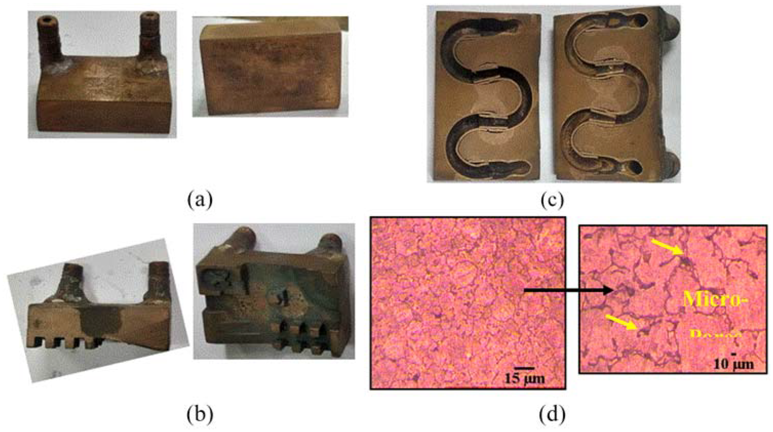
Fabricated (a) rectangular, (b) complex shape RMECC electrodes, (c) cross-section view of the electrode and (d) microscopic image of the sintering electrode at optimized sintering cycle.
Analysis of EWR
The ideal performance of an EDM electrode is not only to cut or remove the maximum material during machining of the workpiece, correspondingly, it should also sustain from the self-erosion. The comparison of the EWR using a solid copper electrode, RME and RMECC for rectangular and complex shape electrodes is shown in Figure 5. The EWR using RMECC was found to be 27.78% ± 1.24% lower as compared to the RME. Also, the RMECC found to have 42.85% ± 1.05% less EWR from the solid copper electrode. EWR in EDM depends upon the electrical erosion, which is generally determined by the combined effect of thermophysical and the mechanical performance. 41 The RME possessed low electrical conductivity as compared to solid copper due to involvement of the isolated pores. Therefore, low spark energy was generated using RME and resulted in low EWR as the solid copper electrode. The solid copper electrode possessed less damaged on the surface after the machining due to higher density (ref. Figure 6). The melted debris was observed on the surface of the solid copper electrode. The RME resulted in low MRR as compared to solid copper which is discussed in the next section. Low EWR in RME could also be due to the flow of dielectric from micro-pores. Due to pressureless sintering, the RME consisted of interconnected micro-pores of size 2–15 µm, as shown in Figure 4(d). The dielectric oil was regularly flowing from the electrode workpiece gap using jets. The micro-pores permitted the flow of dielectric cleaning liquid. 42 The dielectric cooled down the electrode from inside and reduced the EWR. Furthermore, the liquid cryogenic cooling effect enhanced the thermal conductivity of the RMECC electrode and minimized the trap of heat in the electrode. The high amount of melted material and correspondingly cracks were noticed on the surface of RME, and the few cracks and less damage were observed on the surface of RMECC electrode by SEM images (ref. Figure 6). The temperature was observed to be around −35 °C at the opposite surface of the machining face of the electrode for RMECC electrode and 42 °C for the RME. The sudden drop-in temperature decreased the movement in the electrons in metal due to decrement in the thermal vibrations of atoms. This resulted in the sudden increment in the electrical conductivity of the material, which significantly reduces the bulk electrical heating of the metal. The rise in electrical conductivity instantly increased the thermal conductivity of the electrode as per the Wiedemann–Franz–Lorenz law. 43 It quickly removed the heat from the surface of the electrode, as discussed above. It directly reduced the excessive melting and vaporization of the electrode material and improved the electrode life.
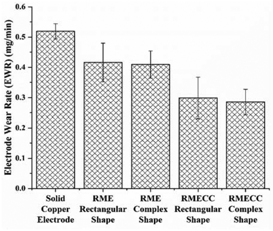
EWR using solid copper electrode, RME and RMECC with rectangular and complex shape for machining of D2 steel workpiece.
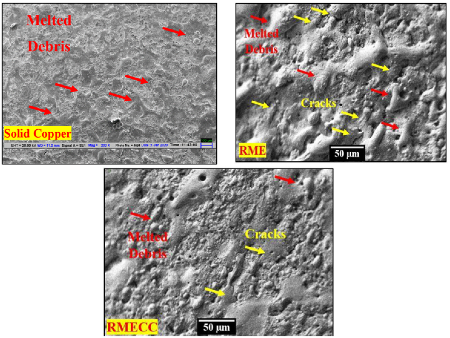
SEM images of the solid copper electrode, RME and RMECC after machining.
Generally, in EDM, the pyrolysis of dielectric takes place due to electrical discharge. The carbon atoms come out and directly deposit on the face of the worn electrode and the machined workpiece to form a blackish layer. The thick formation of carbon layers on the RME electrode was noticed as compared to RMECC electrode (ref. Figure 7(a)). The formation of thick carbon layer created a barrier to transfer the heat through electrodes. Therefore, the extra amount of current was required to execute the EDM operation. It directly provided the untoward effect on the electrode with extensive wear and also shortened the tool life. The cryogenic cooling in the electrode improved the electrical and thermal properties of the electrode as discussed above. The heat gets dissipated rapidly from the electrode, which suppresses the deposition tendency of carbon atom and formation of any carbides. Therefore, a thin blackish layer was observed on the RMECC.
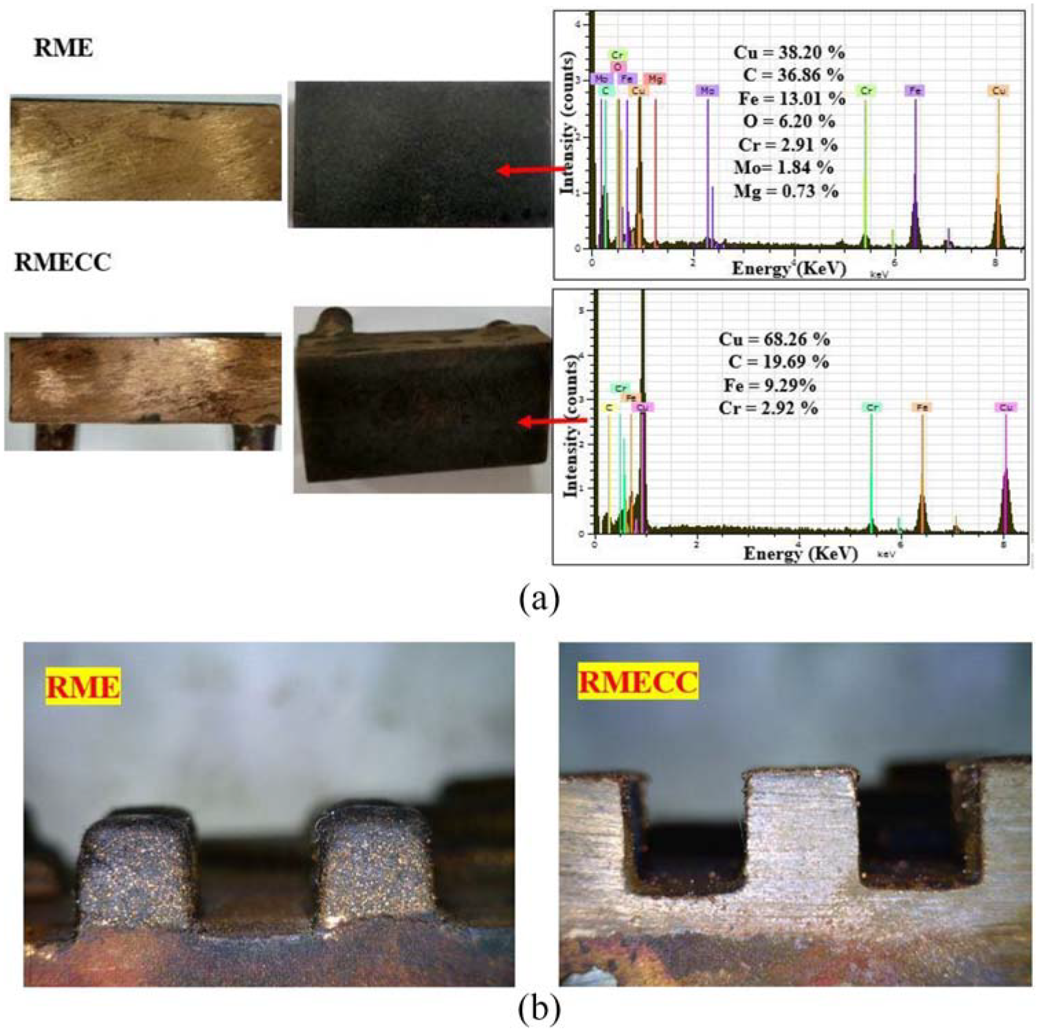
(a) Side view and EDX analysis and (b) worn edges of RME and RMECC after machining.
In addition, EDX analysis was performed on the electrode surface for the carbon percentage evaluation. The excess amount of carbon was noticed on the RME surface by EDX analysis in contrast to the RMECC surface (ref. Figure 7(a)). The low deposition of carbon also signified the less EWR for RMECC. The small percentage of iron and chromium was also observed in RMECC as compared to RME, which meant the less deposition of melted workpiece on the electrode face. The effect of reduction in EWR was also studied on the sharp electrode edges.
Damage to the sharp corners was observed by the microscope study for RME after EDM (ref. Figure 7(b)). Due to isolated pores on the rapid manufactured electrodes, the sharp corner resulted in low strength. The porosity resulted in the corner wear by the early melting of the electrode. The similar damage to the sharp edges was also observed by Rennie et al. 28 for the EDM electrode fabricated by 3D printing and electroforming. However, due to cryogenic cooling, the RMECC resulted in less melting and vaporization of the electrode material as discussed above. This resulted in less damage to the sharp corners of the RMECC (ref. Figure 7(b)), and the electrode could be used for multiple times. Moreover, Srivastava and Pandey 15 also noticed less out-of-roundness in electrodes after machining using cryogenic cooling assistance during EDM.
Analysis of MRR
Figure 8 depicts the MRR of workpiece machined by the solid copper, RME and RMECC electrodes. The MRR in RME electrode was less as compared to the solid copper electrode could be due the low electrical conductivity of the sintered RME electrode (40.98 MS/m) which provided less spark energy as compared to the solid copper and resulted in low MRR. The MRR was found to be less in RMECC electrode as compared to RME and solid electrode due to reduction in the temperature of dielectric between the vicinity of the electrode and workpiece by electrode cooling. 14 Therefore, some of the electric spark energy was employed to heat-up the dielectric to room temperature. The other portion was utilized in the form of a plasma channel for the melting of the workpiece. This resulted in the cause of smaller crater formation. 44 Similar observations were noted from the SEM images of the workpieces machined by the solid copper electrode, RME and RMECC (ref. Figure 9(a) and (b)). The high electrical conductive solid electrode possessed high electric spark during machining, and the workpiece melted faster due to high temperature. This resulted in formation of pores, cracks and debris on the workpiece surface. On the other side, RME possessed less spark energy and resulted in low quantity evaporation of workpiece which resulted in formation of small cracks and low recast layer on the workpiece. The fewer debris globules, pin-holes, volume of craters and pock-marks were obtained on the workpiece machined using RMECC as compared to the RME and solid copper electrode.
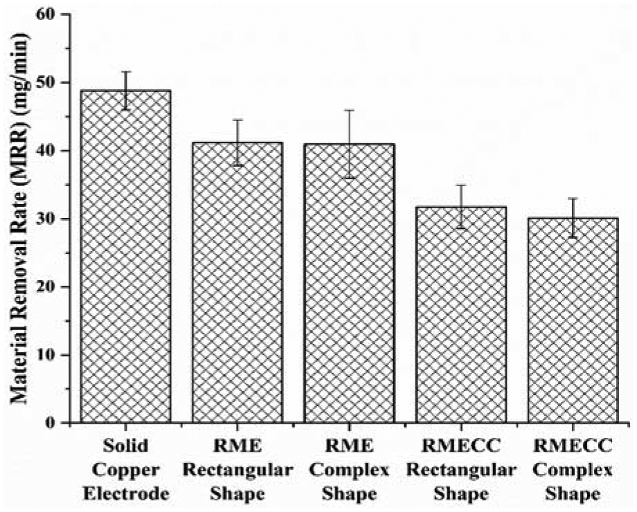
MRR using solid copper electrode, RME and RMECC with rectangular and complex shape for machining of D2 steel workpiece.
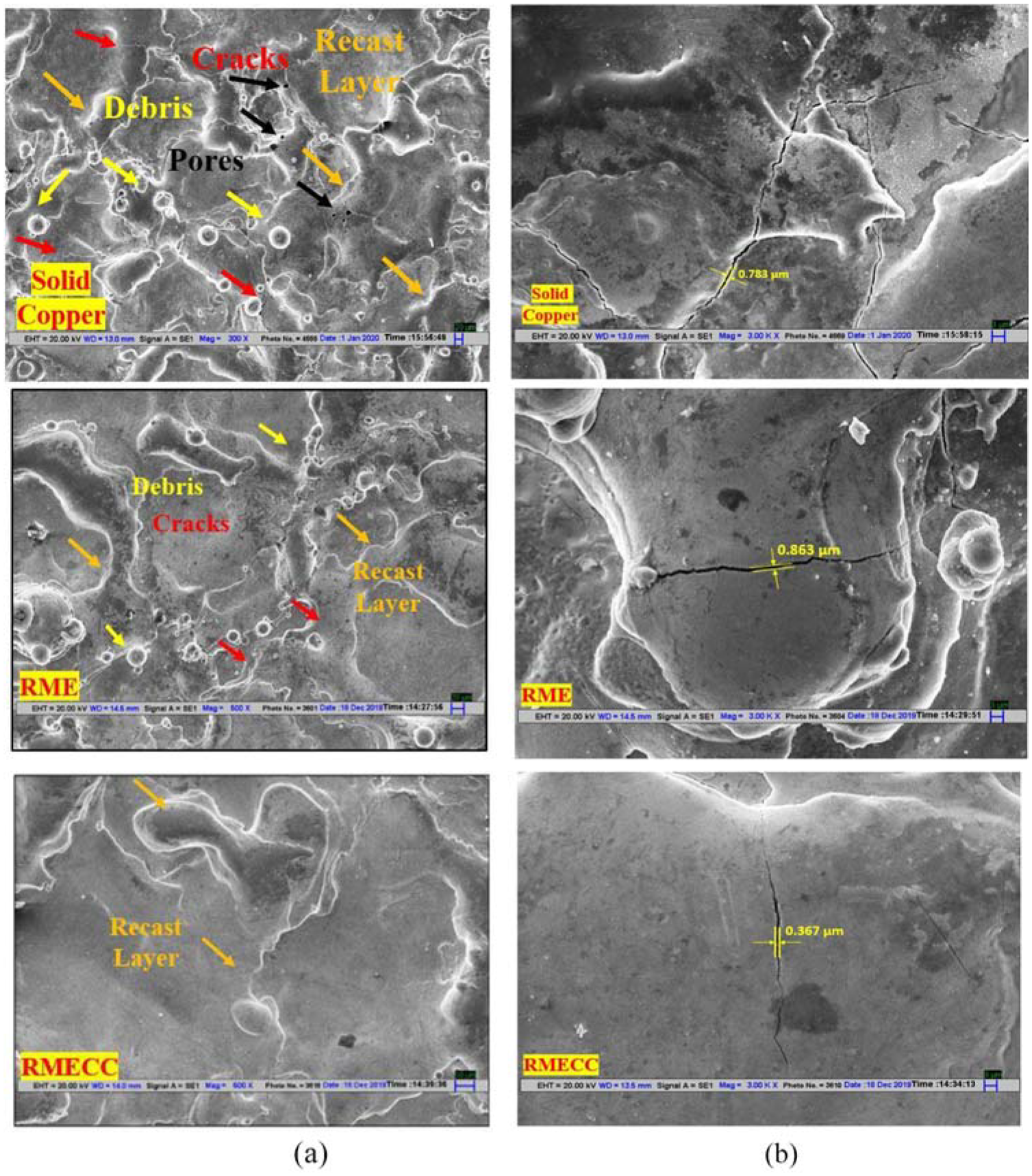
SEM images of (a) surface morphology, and (b) cracks of workpiece machined by solid copper, RME and RMECC.
The cracks are formed when the contraction stress surpasses the workpiece material ultimate tensile strength. 45 The less surface crack size was observed by the RMECC tool (∼0.367 µm) as compared to RME (∼0.863 µm) and solid copper electrode (∼0.783 µm) (ref. Figure 9(c)). It was due to the reduction in average temperature around the crater by the electrode cryogenic cooling. This caused less residual stresses in the workpiece 46 and formed fewer width cracks. However, the recast formation was found to be greater prominent by the RMECC as compared by RME. It was also due to the reduction in dielectric temperature between electrode and workpiece gap, which smoothly re-solidify the removed debris on the workpiece surface. It resulted in smooth surface texture which was identified by the optical surface profiles of the workpieces (ref. Figure 10). The high peaks on the surface profile were observed from the workpiece machined by solid copper with 176.69 ± 11.4-µm SR, RME with 141.15 ± 8.2-µm SR and low with smooth peaks on the surface profile was observed by the RMECC tool with 65.12 ± 3.45-µm SR. The heat dissipation capacity was enhanced due to the cryogenic cooling and directly increased the heat transfer rate as discussed above. Therefore, the melted material uniformly cooled down rapidly and deposited smoothly on the workpiece cavity. This hassle-free recodification in the case of RMECC usage might increases the thickness of the recast layer. 10 However, the uniform deposition would result in less residual stresses and would reduce the probability of surface crack formation to some extent. The less crack formation in small size was also confirmed from the SEM images of the machined cavity as discussed above.
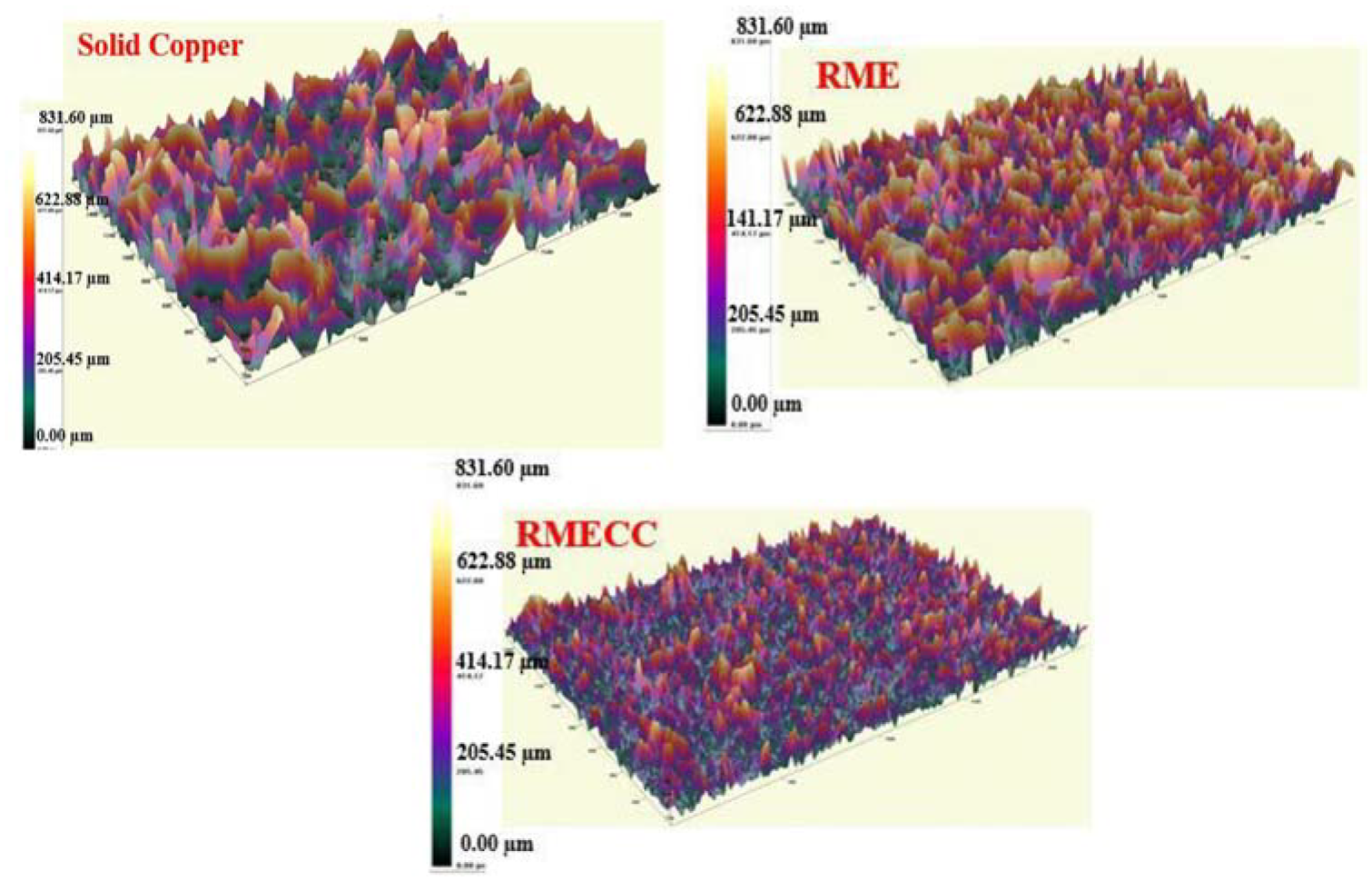
Optical surface profile of workpiece machined by solid copper, RME and RMECC.
The XRD technique was used to analyse the phase formation on the machined surface due to EDM. The primary contents of the D2 steel in pure form are iron, carbon, chromium and cobalt (ref. Table 1). However, due to the carbon enrichment on the machining zone by pyrolysis of the dielectric medium, carbides formation was revealed after EDM. Figure 11 depicts the XRD peaks of the machined surface after EDM with RME and RMECC. The XRD analysis identified the presence of the matrix of iron carbide (reference code: 00-017-0333), cobalt carbide (reference code: 00-044-0962), chromium carbide and ferrite (reference code: 00-006-0696). These carbides were anticipated to be deposits on the grain boundaries of the workpiece. The XRD peaks were noted in the similar positions for the workpieces machined by RME and RMECC. The low intensity of the large peaks revealed the less formation of cracks, which were noticed earlier. Similarly, Rahul et al. 10 observed less formation of cracks on the workpiece and less residual stresses by the cryogenically treated electrode in contrast to the conventional EDM. Therefore, less formation of cracks and low-intensity phase formation by RMECC help to improve the fatigue life of the end product.
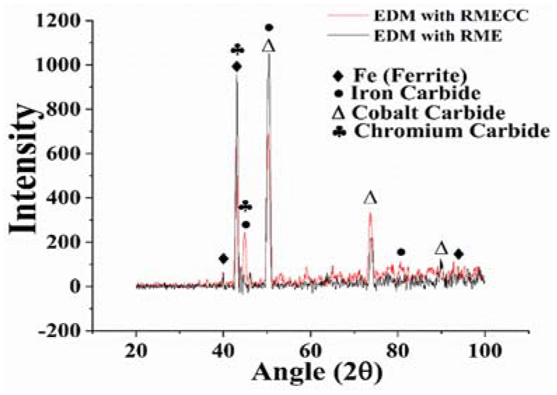
XRD analysis of workpiece machined by RME and RMECC.
Analysis of cavity shape dimensions
It is worth to mention here that the present study was focused on fabricating cryogenic cooling channel electrode using the RM process for the machining of complex shapes on the workpiece. Therefore, the optical microscope study was performed to measure the dimensions of the fabricated cavity on the workpiece with RME and RMECC electrodes. First, the optical microscope was calibrated with the standard scale and subsequently, readings were taken precisely. The optical microscope measurements of the workpiece machined by complex shape RMECC is shown in Figure 12.
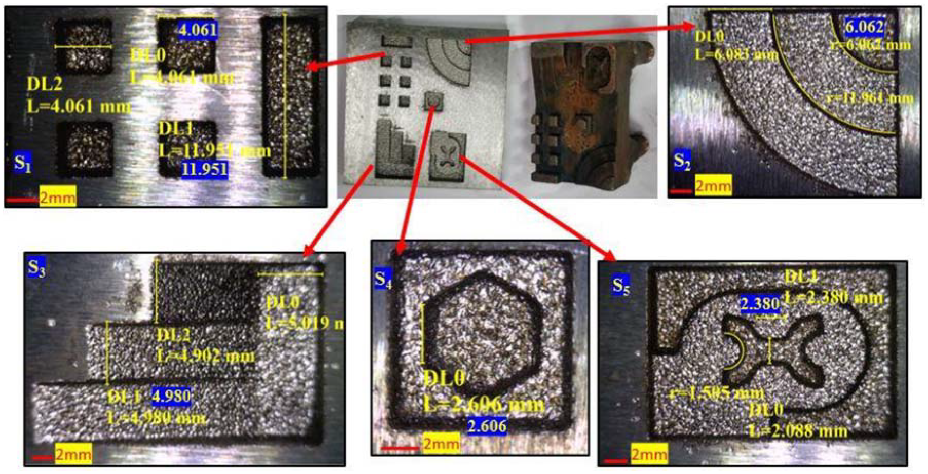
Dimension analysis of the complex shape features on the workpiece machined by RMECC.
Table 2 depicts the comparison of the complex shape cross-section CAD dimensions, fabricated electrode with RM dimensions, machined surface dimensions using RME and RMECC. The electrode was fabricated at the optimized sintering cycle to obtain maximum density, electrical conductivity and minimum shrinkage. 38 Therefore, the fabricated electrodes resulted in shrinkage as compared to the CAD model dimensions. Generally, the EDM process results in cavity overcut on the workpiece with respect to the electrode dimensions, which could be adjusted by the parameters study. 47 The EDM parameters used in the present study were optimized to achieve maximum MRR and minimum EWR and dimensional deviation of the machined cavity as compared to the CAD model. 39 Therefore, the complex shape cavity dimensions were found to be near about the CAD model dimensions machined with the RME (ref. Table 2). The cryogenic cooling during EDM minimized the heat-trapping in the electrode due to increment in thermal conductivity, which directly resulted in the reduction of EWR and improvement in the electrode surface characteristics as discussed above. Therefore, the RMECC electrode possessed better performance, which resulted in minimum dimension deviation of the cavity with respect to CAD model.
Dimensional measurements of the complex shape electrode CAD model, fabricated electrode and obtained cavity after EDM.
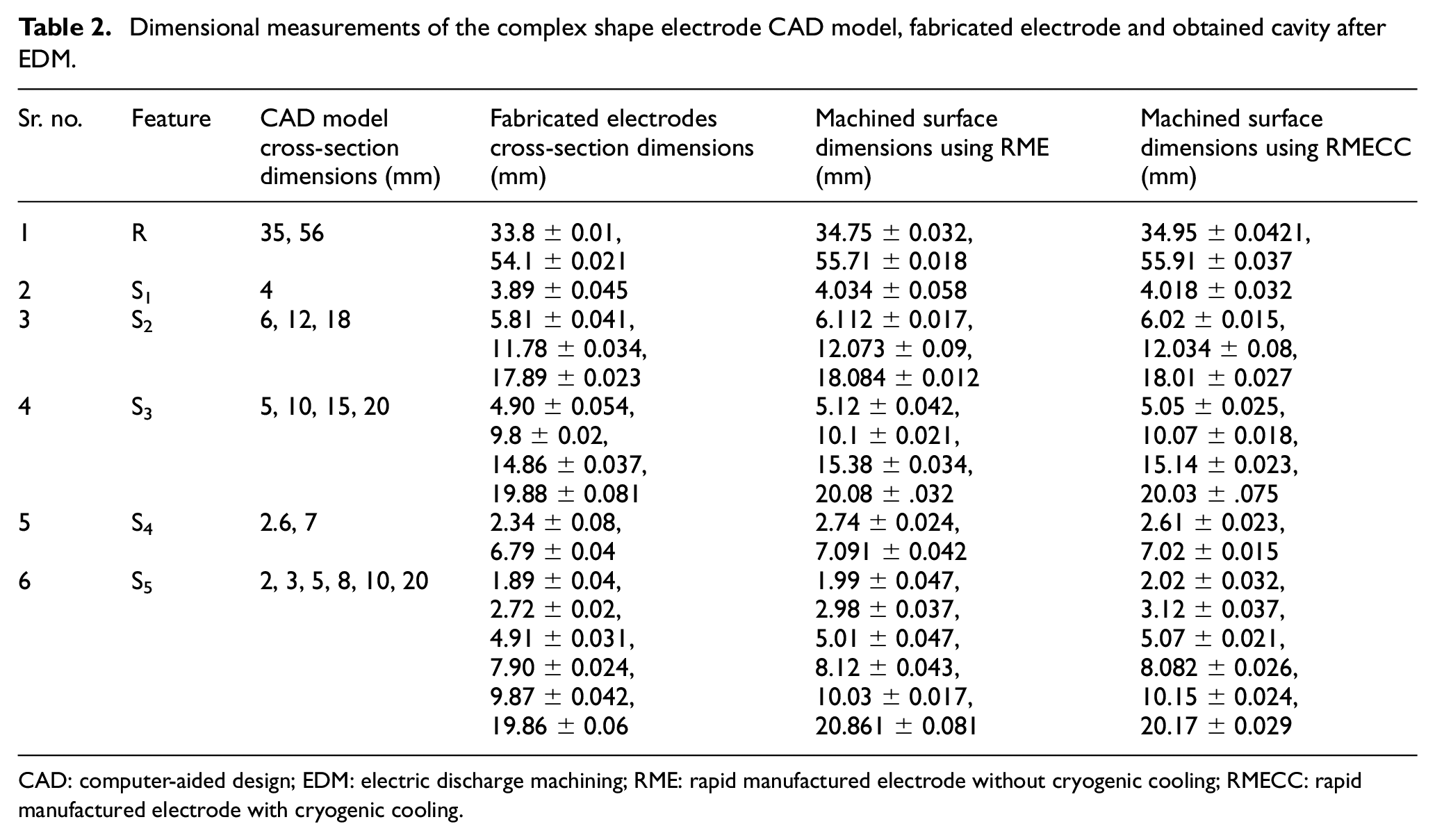
CAD: computer-aided design; EDM: electric discharge machining; RME: rapid manufactured electrode without cryogenic cooling; RMECC: rapid manufactured electrode with cryogenic cooling.
Conclusion
The objective of the present study was to rapid manufacture an EDM electrode with the cryogenic cooling channel for the machining of customized and complex shapes on hard material with the low EWR and better workpiece surface characteristics. Following points were summarized from the present study:
Developed RM methodology with the combination of polymer 3D printing and pressureless sintering was capable of fabricating complex shape pure copper EDM electrodes with cooling channels without any blockage. The micro-pores signified the efficient diffusion between the copper spherical particles.
The reduction in EWR by RMECC was found to be 42.85% from the solid electrode and 27.8% from the RME. The cryogenic liquid in the RMECC electrodes increased the thermal conductivity of the electrode and dissipated the heat generated at the surface of the electrode rapidly after the machining. This resulted in less deposition recast layer and fewer cracks on the electrode surface. The thin layer of carbon was observed to deposit on the RMECC as compared to RME, which signified high electrode life. The cooling effect also provided less damage to sharp corner edges of the fabricated electrode.
The RMECC resulted in low MRR as compared to the RME and solid copper electrodes. The reduction in dielectric temperature due to cooling between electrode and workpiece gap smoothly re-solidify the removed debris on the workpiece surface. This significantly resulted in less formation of holes and cracks on the workpiece surface and provided smooth texture surface profile. The XRD peaks demonstrated the formation of carbides on the machined cavity by both RME and RMECC.
The fabricated RMECC was competent to machine complex shape geometries on the workpiece more precisely than the RME electrode.
Hence, the developed complex shape EDM tool with cooling channel using 3D printing and pressureless sintering could be used for the machining of custom shape dies of hard materials for different applications.
Footnotes
Declaration of conflicting interests
The author(s) declared no potential conflicts of interest with respect to the research, authorship, and/or publication of this article.
Funding
The author(s) received no financial support for the research, authorship, and/or publication of this article.