
Abstract
Leveling process is usually used to minimize the plate defects including flatness imperfections and uniformity of internal stress in the plate industry. Roller intermeshes are important parameters in the leveling process to ensure the high-quality leveled plate. Some current researches treat the plate as a simple beam and ignore the stress superimposed effect to study how to set the roller intermeshes. This article presents an analytical optimization model to search the optimal entry and exit intermeshes for each incoming plate with consideration of the relationship between the roller intermeshes and bending curvatures during the whole leveling process. The optimization model was solved and the results were verified with production data. The relationship between the optimal roller intermeshes and plate thickness, yield stress, and Young’s modulus were discussed in details. It was found out that the roller intermeshes can be set the same for different incoming plates but with equal elastic limit curvature. A four-dimensional database of optimal roller intermeshes about different elastic limit curvature, expected plastic strain ratios, and roller spaces was built. The roller intermeshes can be quickly tracked in less than 1 s as long as the thickness, yield stress, and Young’s modulus of incoming plate and roller space are given according to the database so that it can be used effectively on the leveling production line.
Introduction
Plates are widely used for general engineering purposes. However, conventional plates rolling process often yields some defects such as curl, gutter, middle waves, and edge waves due to non-uniformity distribution of residual in-plane normal stresses. They are normally resulted from improper roller positioning during rolling, difference in transformation during cooling, and improper placement during transport. To improve the quality of the rolled plate, the leveling process is designed to reduce these defects before the secondary manufacturing process.
The leveling parameters include roller intermeshes and roller bending deflection. If roller intermeshes are optimized and set well enough to get the high-quality plate, it is unnecessary to set roller bending deflection. Therefore, the roller intermeshes are the more important leveling parameters while the roller bending deflection is just the auxiliary parameter. It is necessary to discuss the relationship between roller intermeshes and bending curvature before studying and optimizing roller intermeshes. Bending process is a reversed application of the leveling process. Zhang and Tian 1 analyzed plate residual stresses and strains distribution considering multi-step bending forming effect using both the theoretical method and numerical method. They found the residual stresses and strains decrease at the initial loading position along the thickness direction during the forming process of subsequent loading positions. Mechanical stress-inheriting behavior of a piece of strip metal should be also considered during the roller leveling process, because it has a non-negligible effect on the evolution of final residual stresses distributions and geometric imperfections. 2 Some researchers simulated and predicted the leveling process using the finite element method (FEM).3,4 Although the FEM result such as residual stress have good consistence with the experimental result, it is difficult to use this method in practice because it is time consuming. To find an effective model to simulate the leveling process. Kadota and Maeda 5 and Higo and Matsumoto 6 originally proposed the curvature integration model which describes the relationship between the curvature and reduction of rollers. It lays the foundation of the leveling technology analysis. They solved it by an algorithm with eight steps and two loops. However, it may easy to fail to achieve the final results if any loop is not convergent. Xue et al. 7 used a decouple method to solve Kadota and Higo’s model for finding curvature distribution. The convergence of simulation results still depends largely on contact angles. Liu et al. 8 further proposed a new method to analyze this model in less than 5 s by solving nonlinear equations directly to discuss the curvature and residual stress distribution in the thickness direction. This method is helpful to search and optimize the ideal roller intermeshes due to its analytical time advantage. The decoupling research about the relationship between roller intermeshes and bending curvature is just the first step to find the optimal roller intermeshes. The reason is that roller intermeshes need to be modified carefully several times to check whether the quality of leveled plate satisfy the industry demand. Doege et al. 9 developed an analytic forming model and control system. This system continuously adjusted the roller position until the measured leveling force match the calculated forces to get the optimal roller intermeshes. Park et al. 10 found an optimal entrance intermesh condition which is able to remove the blanking bow or deviation of curvature of a sheet by finite element analysis for initially curved three strips by applying virtually divided strip model. Cui et al. 11 attempted to summarize the influence of the roller intermesh, initial curvature and tension force on the plastic strain ratio, residual stress, residual curvature, and leveling force by treating the plate as a simple beam and ignoring the stress superimposed effect. They found that the residual stresses and curvature converge to a small range under a high plastic strain ratio. Yin et al. 12 studied the section steel leveling process on a flexible roller system based on spring back theory. They believe that the large and small deformation leveling strategy definition is helpful to set reasonable roller intermeshes according to different plate. Also, they improve the section steel leveling quality by adjusting the last rollers. Hamasaki et al. 13 proposed optimization method reliability study for the determination of tension leveling process combining finite element simulation and numerical stochastic optimization method. To cut computing time and decrease probability of failure estimation, Monte Carlo simulation and response surface with Moving Least Square Method were used. The obtained result is more reliable than the optimum obtained by the ordinary deterministic optimization method. And the tolerances of the initial yield stress and Young’s modulus have a great influence on the residual curvature. Leveling can also be used to level bar and pipe. Pei et al. 14 and Wang et al. 15 proposed a three-point parabolic fitting method and a flow chart of prediction application of bending straightening model to predict the press head downfeed distance to level the shaft and longitudinally submerged arc-welded (LSAW) pipe according to its initial measured bending shape. They increased the press head load until the real-time curvature is close enough to the calculated bending curvature. Similarly, Kim and Chung 16 designed a multi-step straightness real-time control system with fuzzy self-learning method to minimize flatness error of deflected shafts. This system can choose straightening point and desired deflection according to shaft size and material properties. Huh et al. 17 proposed leveling process parameters optimization research to eliminate the undesirable curvature of a thin-walled aluminum pipe for a multi-staggered 14-roller leveler. The intermesh and the slanted angle of rollers were chosen as variables to respond to the plastic strain along the pipe length. They found the leveling quality and residual stress are sensitive to the variables. The similar conclusion was also found by Rocha et al. 18
Based on the aforementioned discussion, the relationship between roller intermeshes and bending curvature analysis was theoretically and experimentally studied well. It means the final flatness can be judged according to continuous simulated results which needs much more time. Therefore, it is necessary, though difficult, to find the reasonable roller intermeshes quickly with consideration of the relationship between roller intermesh and bending curvature during the whole leveling process. This article presents our work toward this goal. Section “Formulation of optimization model” presents a nonlinear roller intermeshes optimization model based on the curvature integration method. In section “Optimization results and verification with production data,” the optimization results are verified with production data. Section “Relationship between roller intermeshes and plate characteristics” summarizes the relationship between the optimal roller intermeshes and initial plate characteristics parameters so that the they can be found in less than 1 s for a given plate, expected plastic ratio, and inter-roller distance. Finally, the conclusions are given in section “Conclusion.”
Formulation of optimization model
The equipment which carries out the leveling process is called the leveler. The structure of levelers went through three revolutions historically. The first- and second-generation levelers were designed to level thick plate (25–60 mm) and medium plate (6–25 mm) (shown in Figures 1 and 2). The roller intermesh was controlled by a screw down system in the past two generation levelers. To further level wider leveling range (6–60 mm) and get higher quality plate, third-generation levelers were designed, as depicted in Figures 3 and 4. Two separate upper beams are linked by a hinge in Figure 3, and the roller bending deflection is driven by the roller bending cylinder. The roller bending deflection is given by four inner cylinders hidden in the single upper support beam shown in Figure 4. We designed the later third-generation leveler that is taken as an example to illustrate the leveling process. The lower support beam of the later leveler is fixed on the frame while the upper support is connected to four hydraulic cylinders. The roller bending cylinders are mounted and hidden in the roller bending box for the compensation of roller deflections. The locking device is designed for the purpose of changing rollers quickly. The pressure and distance signals of four hydraulic cylinders are controlled by AGC (automatic generation control) control system to compensate the upper support beam elastic deformation and make sure the roller intermeshes match the preset values. The leveling technology database can save each leveled plate information such as thickness, width, and yield stress of incoming plate and their leveling forces and torques. Therefore, the database can set roller intermeshes automatically for similar incoming plate.
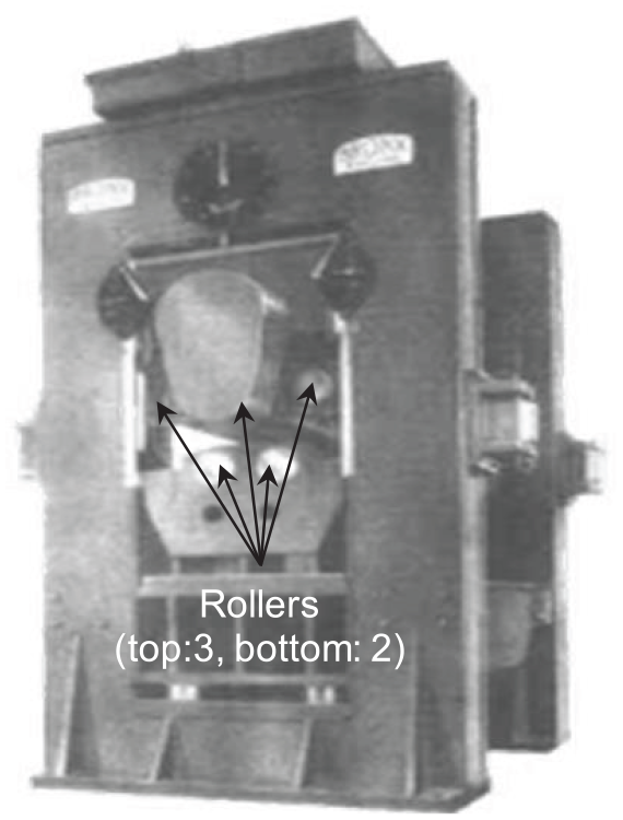
First-generation leveler.
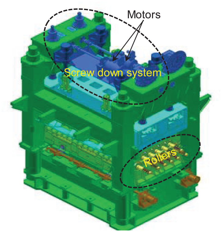
Second-generation leveler.
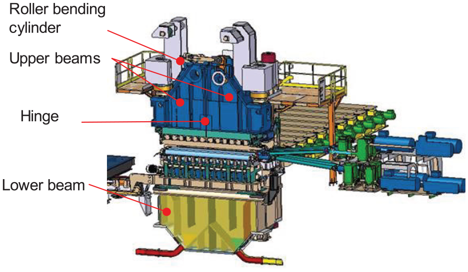
One kind of third-generation leveler.
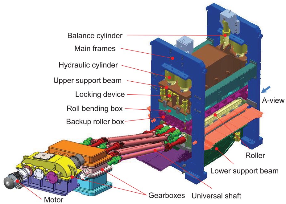
Another kind of third-generation leveler.
The basic leveling parameters are the entry and exit roller intermeshes, δ2 and δN–1, which are set by hydraulic cylinders in advance. Upper rollers are mounted on the upper support beam, which is uniformly spaced. The first bottom roller is capable of roller intermeshes adjustment to improve biting condition. The position of the final bottom roller can also be controlled to assist the leveling quality of the plate. Therefore, the other bottom rollers are mounted on the lower support beam, which is also uniformly spaced as well except the first and final rollers, as depicted in Figure 5. p1 and pn is larger than p/2 (p1 = pN = 195 mm, p = 300 mm). Each top roller is positioned between two adjacent bottom rollers along the plate traveling (or x) direction. The gap between the top roller and the bottom roller along the z-direction increases proportionally along the plate traveling direction, as shown in Figure 5. Therefore, once δ2 and δN–1 are set, other δi values can be easily computed. The plate is forced into elastic–plastic deformation in alternating direction by staggered gaps between top and bottom rollers.
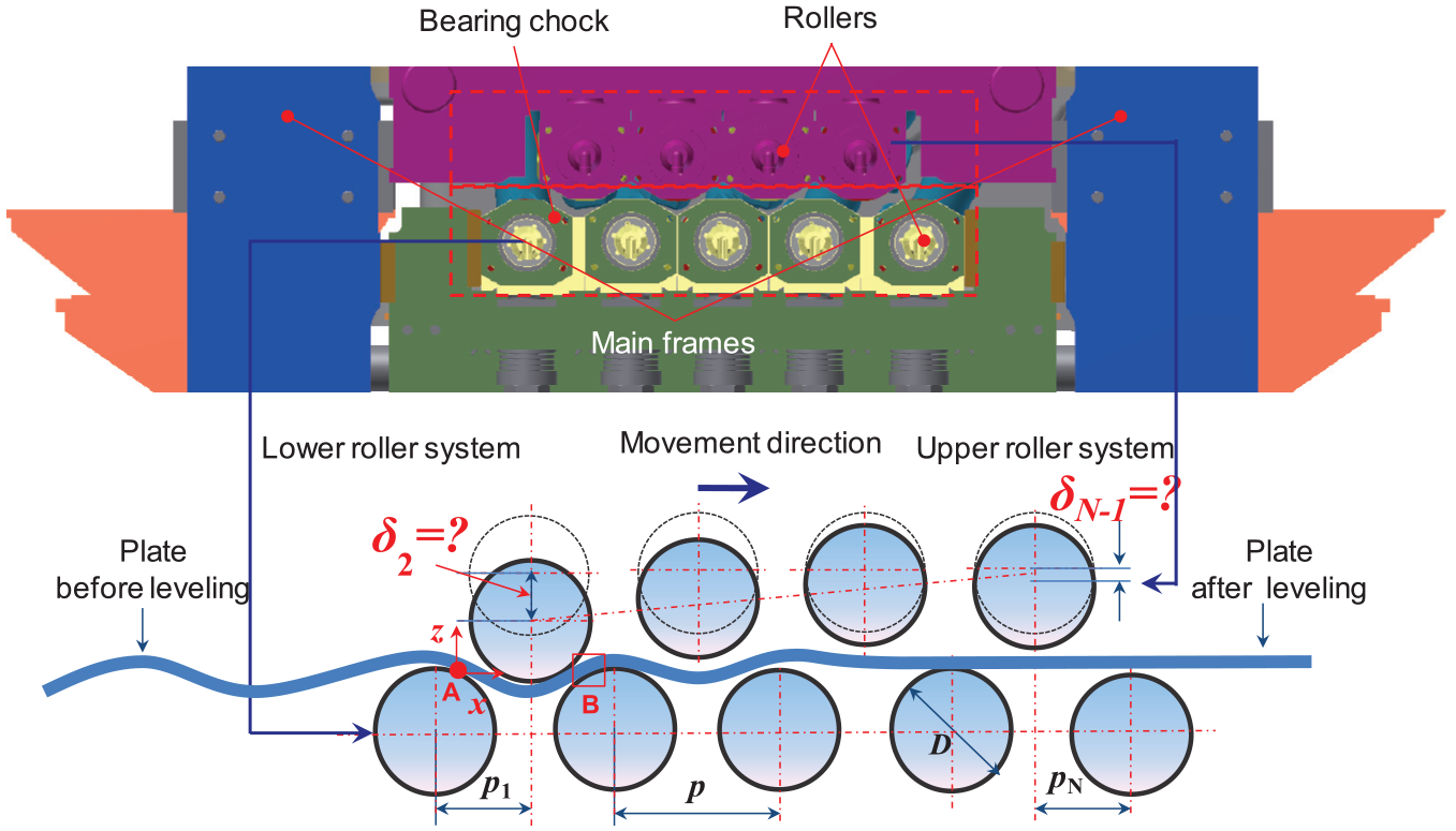
Roller configuration.
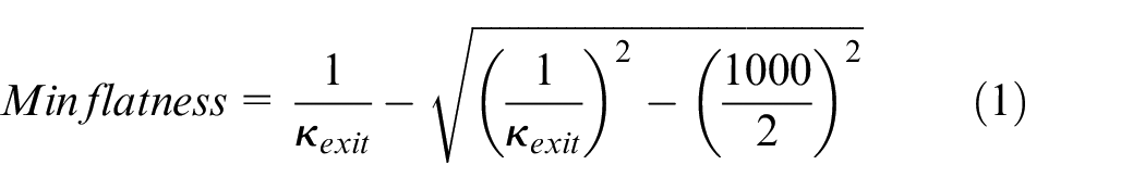
Different roller intermeshes will result in different qualities of the leveled plate. Finding the best possible roller intermeshes is formulated as a nonlinear optimization problem. To ensure the minimum final flatness after leveling, δ2 and δN–1 are defined as the process design decision variables in the optimization model. The intermeshes can be distributed proportionally according δ2 and δN–1 during the optimization process. The residual curvature tends to be uniform after the leveling process. 8 Therefore, the objective function is to minimize the final flatness (wave height per meter shown in Figure 6) of the plate, namely
where
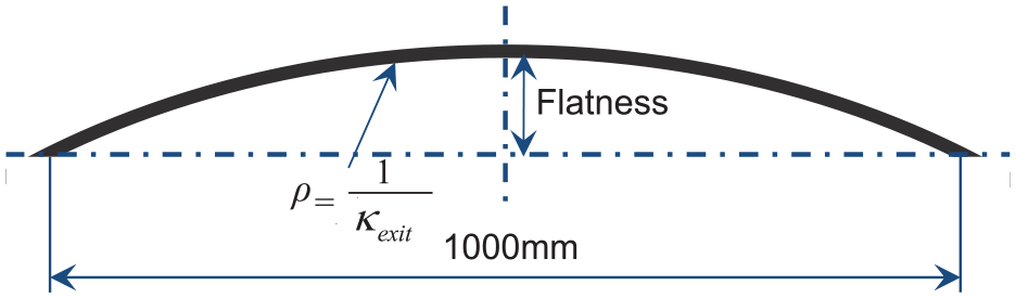
Definition of flatness.
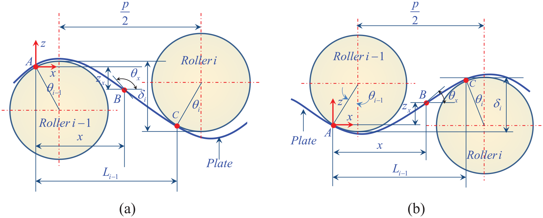
Schematic layout of the curvature integration model. 8
The bending curvature during the leveling process is directly related to roller intermeshes by the following curvature integration model 8
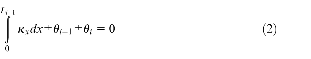
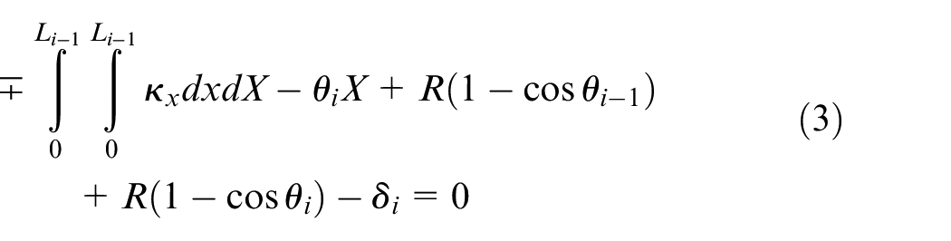
where the sign in equations (2) and (3) depends on the roller ID, i. All rollers are numbered from left to right with the leftmost bottom roller numbered as 1. If i can be divided exactly by 2, the sign in equation (2) is “+” while it is “–” in equation (3). Otherwise, the sign in equation (2) is “–” while it is “+” in equation (3).
The leveling force of roller i, Fi, can be deduced by the moment equilibrium principle
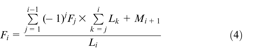
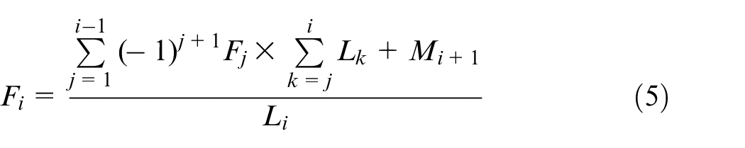
where i is an odd number in equation (4) and even in equation (5), and
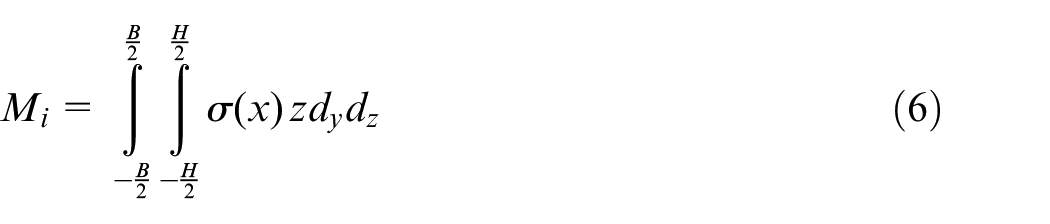
where N is the total number of rollers; B and H are the width and thickness of the plate, respectively; and
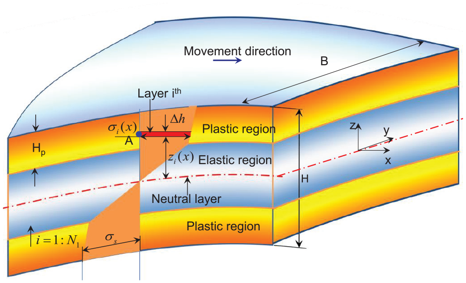
Stress state on the thickness direction (part B in Figure 5).
The bending stress can be calculated by the yield criterion, and the strain in the thickness direction can be expressed as follows

The total power of the transmission system can be calculated by the following equations
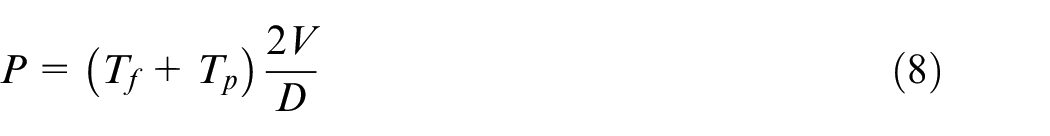
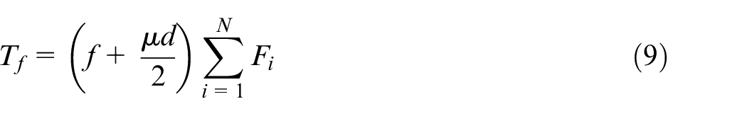
where V is the leveling speed,
The final flatness (wave height per meter shown in Figure 6) of the leveled plate must satisfy the industrial demand, namely
where
To ensure the operational safety, the mechanical parameters such as the leveling force and power must be operated within the machine capacity, that is

where
The plastic strain ratio is an important parameter should be controlled range from 60% to 80% to ensure the quality of leveled plate. Therefore, it should be controlled near the an expected level, namely
where [pl] is the expected plastic strain ratio, pl is the analytical plastic strain ratio distribution, and
The maximum roller intermesh,

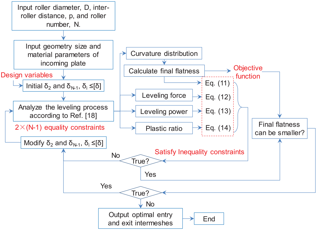
From the aforementioned discussion, the optimization of roller intermeshes is a single objective optimization model subject to a number of 2 × (N– 1) equations and several inequations.
The optimization model solution procedure is summarized in Figure 9. First, the structural parameters, geometry sizes, and material characteristics of incoming plate were entered as input. Second, the design variables, δ2 and δN–1, were initialized. Third, the program in Huh et al. 17 was used to analyze the leveling process so that the curvature and plastic strain ratio distribution were calculated. The leveling forces and leveling power can be calculated by equations (4)–(13). Next, the inequal constraints were checked in the first iterative search loop. Notice that the final flatness was not only treated as the objective function but also defined as one inequal constraint to make sure the final flatness was controlled to meet the industrial demand. The entry and exit intermeshes need be modified if any inequal constraint is not true. The next search loop was to check whether the final flatness can be further smaller. The optimization algorithm is carried out in MATLAB®.
Procedure of optimization modeling.
Optimization results and verification with production data
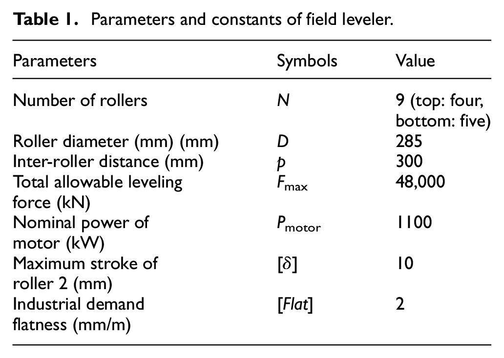
In order to verify the proposed optimization model of the leveling technology, it is necessary to compare the results of the proposed model with production data collected from an iron and steel Corporation. To end this, the initial data of each plate were extracted from 100 online files of their database. The yield stress, Young’s modulus, and thickness distributions of these plate are shown from Figures 10 to 12, respectively. And their elastic limit curvature (ELC) is shown in Figure 13. It is found out that the upper last roller was set to 0 (δ8 = 0) for each plate. The reason is that the incoming plates are easy to be leveled. Only the entry intermesh was chosen as the variable to find the optimal value so that it is easy to operate the leveler. The structural parameters of the field leveler are shown in Table 1. We substitute the parameters in Table 1, geometry sizes, and material characteristics of each plate into the optimization procedure in Figure 9. Then, the optimal roller intermeshes for each plate can be saved and extracted to compare with the actual measured data shown in Figure 14. It can be found that the relative error between the optimized results and measured data can be controlled less than 10% in Figure 15. In general, the production data are slightly higher than the data of present optimization model. The reason is that the hardening coefficient is not considered in the present model due to the high leveling temperature at least of 600 °C.
Parameters and constants of field leveler.
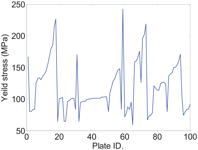
Yield stress of plate ID from 1 to 100.
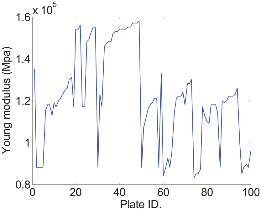
Young’s modulus of plate ID from 1 to 100.
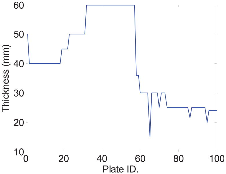
Thickness of plate ID from 1 to 100.
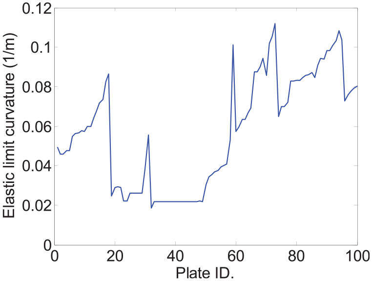
Elastic limit curvature of plate ID from 1 to 100.
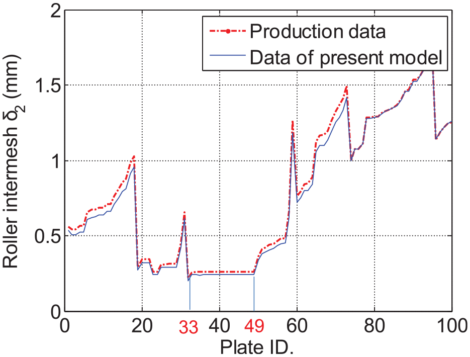
Comparison of optimization results and the production data.
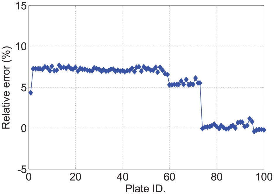
Relative error of optimization results and the production data.
To further validate the leveling forces distributions of each roller, five plates are chosen in Table 2. Leveling forces distribution comparison are shown in Figure 16.
Five plates extracted from Figure 14.
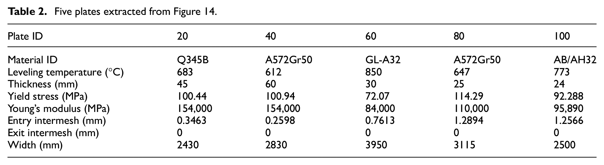
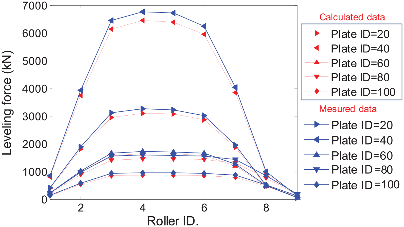
Comparison of leveling forces distribution.
Although there is a good consistence between the obtained optimization results and production data, the optimization procedure in Figure 9 still takes half a minute to find the ideal roller gap for each plate. The reason is that there are 16 equal constraints and 4 inequal constraints needed to be satisfied for the nine-roller leveler during the optimization process in the procedure shown in Figure 9. It is not suitable for real-time control online to process continuous plate with changing characteristics. It is necessary to explore the possible relationship between the optimal roller intermeshes and initial plate characteristics. The purpose is to respond to the roller intermeshes for each incoming plate in less than 1 s as long as their thickness, yield stress, Young’s modulus, and roller space are given for industry online application.
Relationship between roller intermeshes and plate characteristics
It is known that the elastic–plastic states of bent plates not only depend on the material characteristics (yield stress and Young’s modulus) but also relate with the thickness of the plate from previous studies. Hence, it is useful to study the relationship between each individual plate characteristic and the roller intermesh found by the proposed optimization procedure. Based on the results obtained in this study, it can be seen that the relationship between the optimal roller intermesh, δ2, and plate thickness is nonlinear while linear with Young’s modulus and yield stress as shown from Figures 17 to 19.
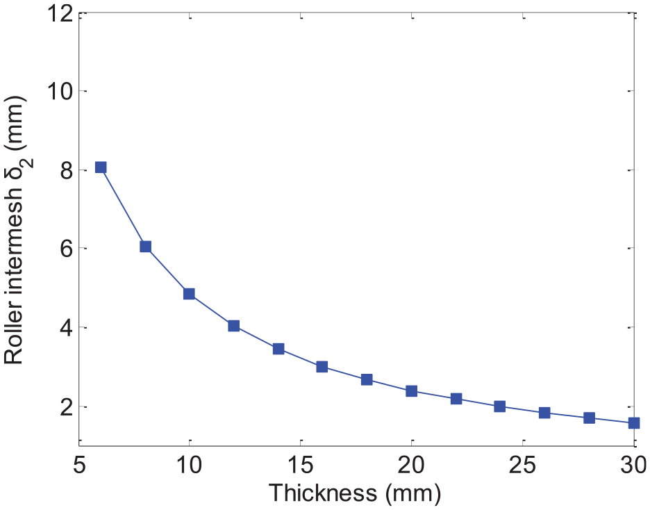
Relationship between δ2 and H (E = 127,510 MPa,
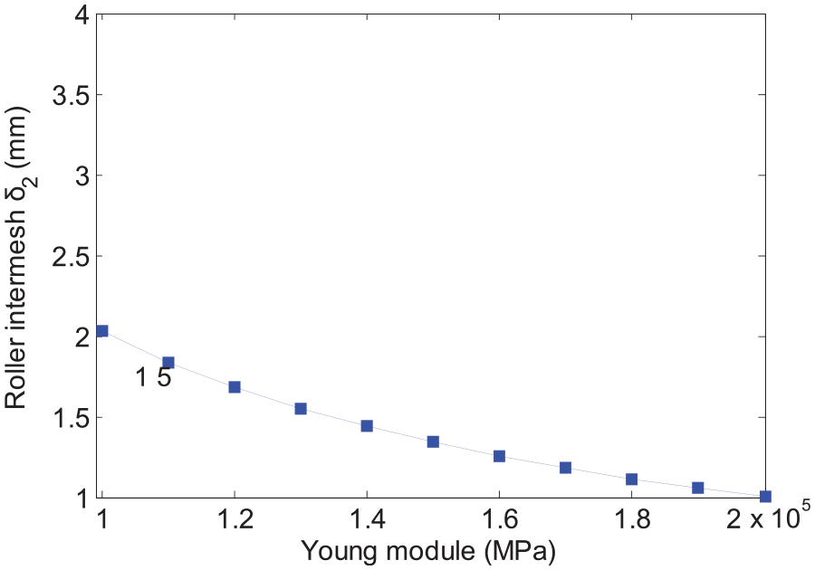
Relationship between δ2 and E (
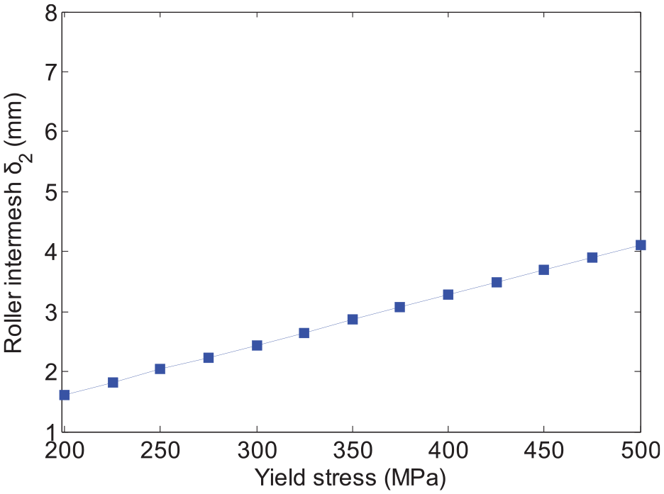
Relationship between δ2 and σs (E = 127,510 MPa, H = 30 mm, and [pl] =75%).
Furthermore, it is interested to discover that there exists a linear relationship between δ2 and ELC,
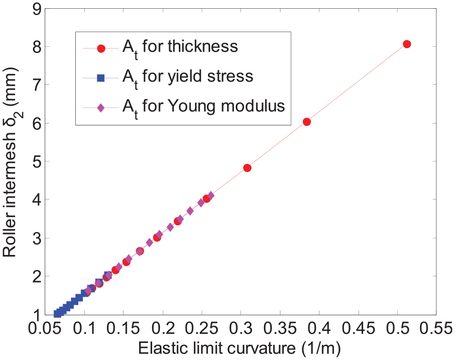
Relationship between
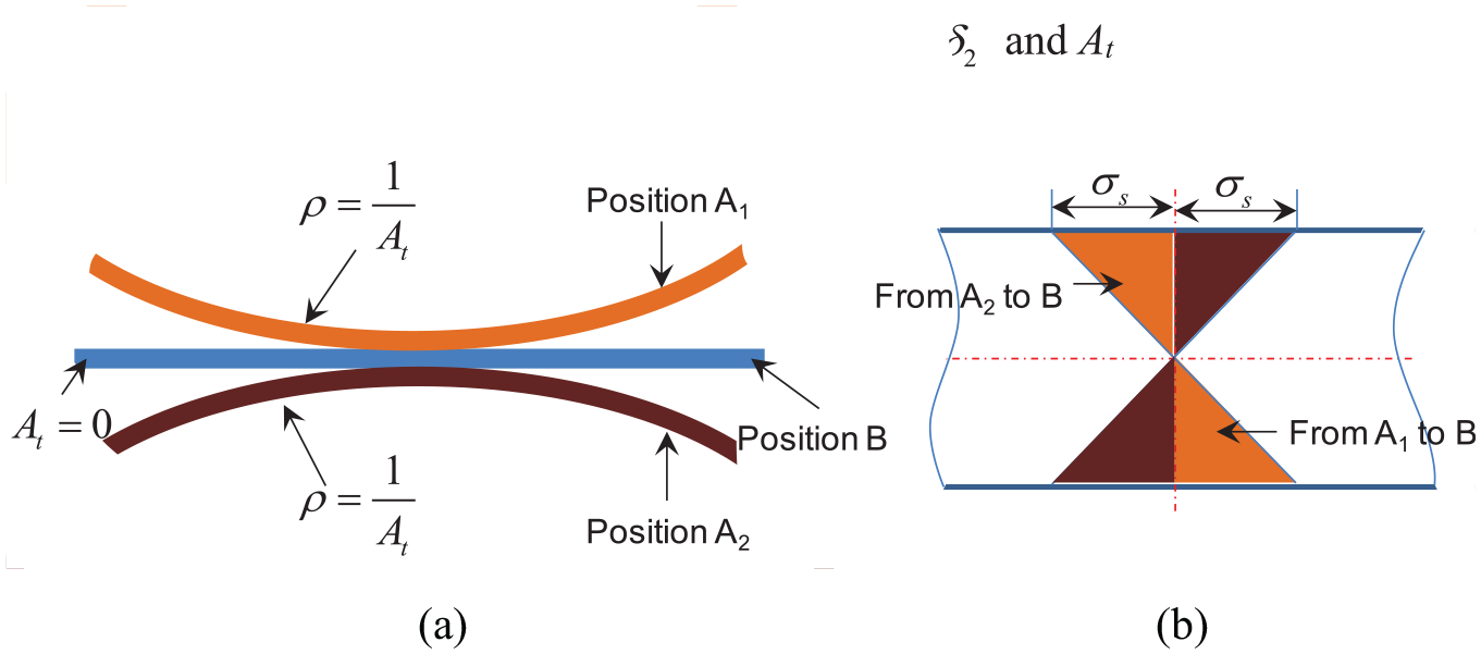
Physical meaning of ELC: (a) bending state and (b) bending stress distribution.
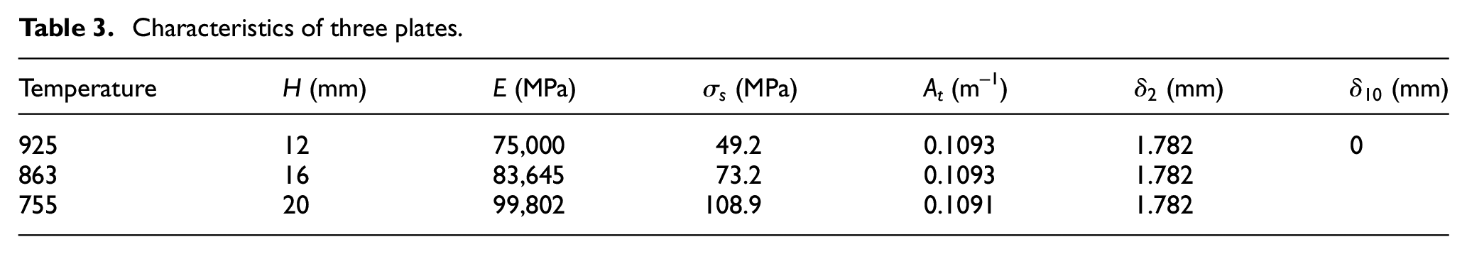
The interesting phenomenon expressed in Figure 20 means that the optimal roller intermesh is the same for plates with varying characteristics as long as their ELC values are equal. To further prove this conclusion, the leveling process for plate with different initial plate characteristics are simulated by the curvature analysis method. 8 The simulated characteristics are listed in Table 3. The curvature distributions of point A in Figure 5 during the leveling process are shown in Figure 22 and they nearly coincide with each other. The initial curvature and corresponding flatness are –0.109/m and 13.6 mm/m, respectively. The residual curvature and corresponding final flatness of the plate are 0.0087/m and 1.1 mm/m, respectively. The corresponding trajectory distributions are shown in Figure 23.
Characteristics of three plates.
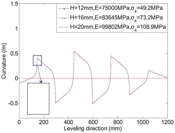
Curvature distributions of point A in Figure 5.
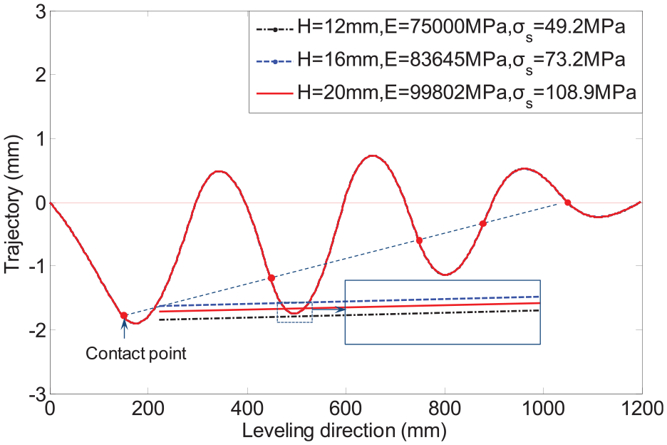
Trajectory distributions point A in Figure 5.
The reason why some roller intermeshes appear to be a constant and some are optimized can be now explained as follow. Substituting the data from Figures 10 to 12 to the ELC,
The plastic strain ratio is another important parameter which affects the quality of leveled plates. It should be chosen selectively for different plates. If the ELC is called the internal factor to determine the roller intermeshes, then the inter-roller distance and the expected plastic strain ratio are the external factors to affect the roller intermeshes. Hence, it is necessary to study how to set the optimal roller intermeshes according to the ELC of a plate, inter-roller distance, and expected plastic strain ratio using the proposed optimization method. Here, δ2 and δN–1 are set as design parameters at the same time for widening the leveling range purpose.
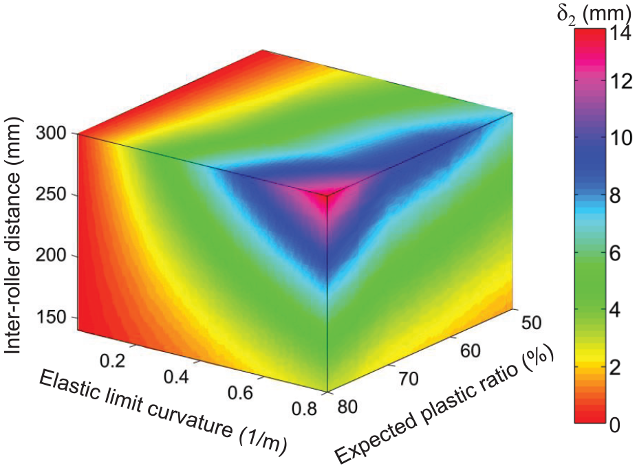
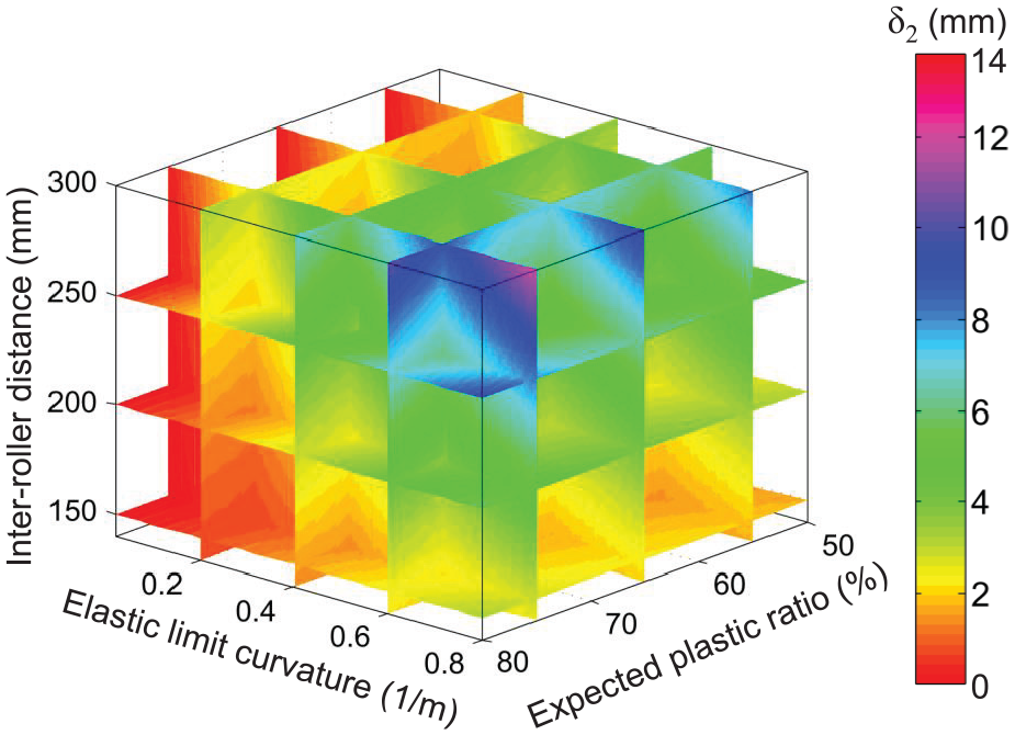
Figure 24 shows the contour of optimal δ2. It can be found that the maximum optimal δ2 value is located at the one corner where the ELC, expected plastic strain ratio, and inter-roller distance reach their maximum values at the same time. The reason is that the larger the three factors, the harder it is to force the plate into plastic deformation. The contour of δ2 is also shown in Figure 25 but in a slice form, indicating the discrete values of the corresponding factors. The corresponding contours of optimal δ8 are outputted in Figures 17 and 18.
δ 2 contour about At, inter-roller distance, and different expected plastic strain ratio.
δ 2 contour about At, inter-roller distance, and different expected plastic strain ratio in slice form.
In summary, the roller intermeshes for leveling a plate on an nine-roller leveler can be calculated quickly according to the results presented in Figures 24 and 26 as long as the ELC ranges from 0 to 0.8, the expected plastic strain ratio ranges from 50% to 80%, and inter-roller distance ranges from 150 to 300 mm, respectively (Figure 27).
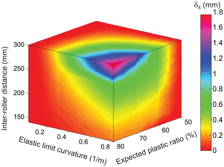
δ 8 contour about At, inter-roller distance, and different expected plastic strain ratio.
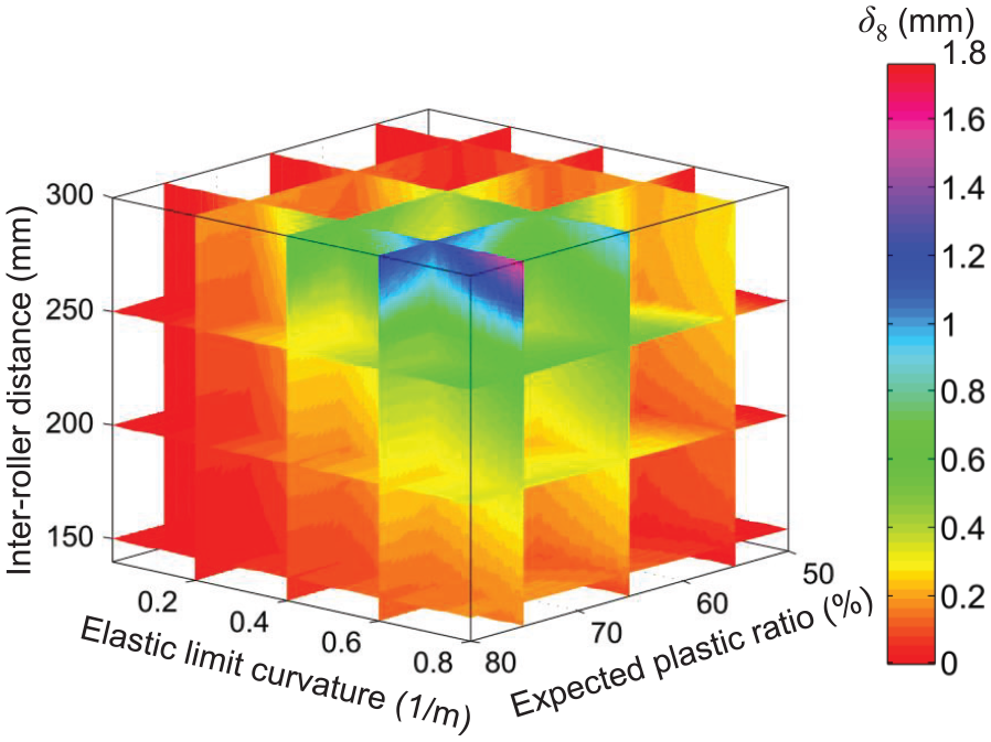
δ 8 contour about At, inter-roller distance, and different expected plastic strain ratio in slice form.
For example, the ELC of a plate (H = 45 mm, E = 54,000 MPa, and σs = 100.4 MPa) is near 0.029. Suppose it is leveled on a nine-roller leveler with inter-roller distance of 250 mm, the roller intermeshes, δ2 and δ8, can be tracked at 0.283 and 0.032 mm, respectively, in less than 1 s according to Figures 28 and 29.
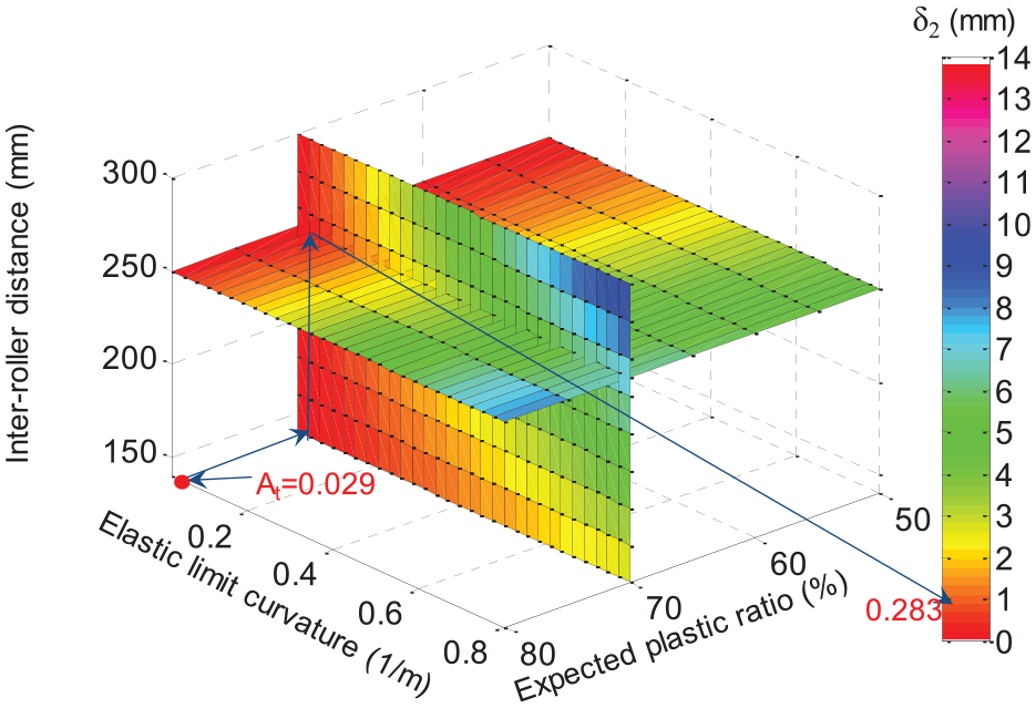
Roller intermesh, δ2, tracking trajectory for a given plate, expected plastic ratio, and inter-roller distance.
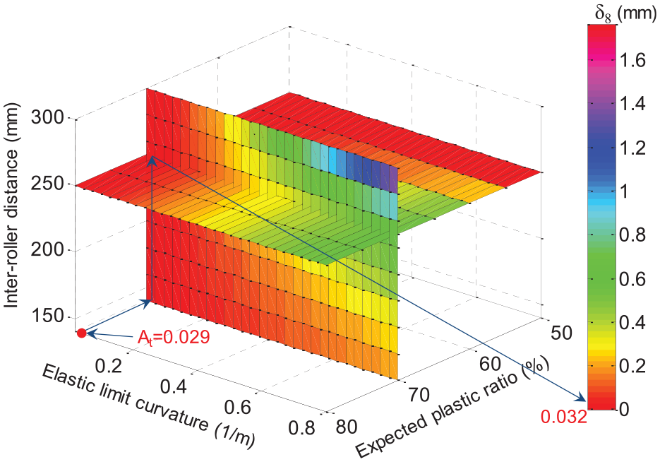
Roller intermesh, δ8, tracking trajectory for a given plate, expected plastic ratio, and inter-roller distance.
Conclusion
Based on the results presented in this article, it has been clearly demonstrated that the proposed optimization model can be used to effectively find the roller intermeshes for the plates leveling process. The following conclusions can be drawn:
The nonlinear leveling optimization model with equality and inequality constraint equations was built based on the curvature integration method. This optimization model was solved for plates with varying characteristics and verified with production data.
The plate thickness has a nonlinear relationship with the optimal roller intermesh values while yield stress and Young’s modulus have linear relationships instead. The initial plate characteristics including the thickness, yield stress, and Young’s module can be transformed to a single value, that is, ELC, At. The roller intermeshes can be set the same for different plates with varying thickness, yield stress, and young’s module as long as they have equal ELC.
The relationship between the optimal roller intermeshes and ELC, expected plastic strain ratio, and inter-roller distance were established. Such relationship is helpful to find the optimal roller intermesh in less than 1 s for any incoming plate to be leveled.
Footnotes
Declaration of conflicting interests
The author(s) declared no potential conflicts of interest with respect to the research, authorship, and/or publication of this article.
Funding
The author(s) disclosed receipt of the following financial support for the research, authorship, and/or publication of this article: This work was supported by Scientific and Technological Research Program of Chongqing Municipal Education Commission (grant no. KJ1600941) and National Science Foundation of China (grant no. 51375521).