
Abstract
Magnesium alloys have been known as the next generation material for lightweight body structures. Pulsating hydroforming is an effective method to improve magnesium alloy sheet forming performance, and the formed parts are characterized by lightweight, high-specific strength and stiffness. The deformation performance of magnesium alloy sheet AZ31B with a thickness of 0.6 mm under pulsating hydroforming has been investigated by means of experimental study, numerical simulation and theoretical analysis. The results show that under the same maximum hydraulic pressure, compared with simple linear loading, the magnesium alloy forming parts with pulsating hydraulic loading not only have better wall thickness uniformity and larger bulging height but also can delay the occurrence of fracture, improve the forming performance and ultimate the forming ability of magnesium alloy sheet. A new evaluation index is proposed to simplify the comprehensive forming performance of magnesium alloy parts with different amplitudes and frequencies more accurately, which can also be applied to determine the optimal forming parameters of magnesium alloy sheet AZ31B in the pulsating loading condition.
Introduction
Magnesium alloys, as the lightest metal alloys in industrial applications, are widely used in many industries, like aerospace and automotive manufacturing.1,2 Based on its close-packed hexagonal structure, the elongation of magnesium alloys is usually less than 20% at room temperature, and thus, its plastic deformation capacity is poor.3–6 In the previous studies, most of the scholars improve the forming performance of magnesium alloys by increasing the forming temperature or refining the grains. For example, Kong et al. 7 made a breakthrough progress in tool design through precise control of temperature distribution of the magnesium alloy AZ31B tubular material, and minimized the defects in tube hydroforming at the evaluated temperatures. Aidin et al. 8 studied the microstructure and texture evolution of a commercialized twinning-induced plasticity automotive magnesium alloy during friction-stir spot welding. Matsunoshita et al. 9 processed a Mg–Li alloy with 8 wt% Li through severe plastic deformations with high-pressure torsion to achieve the ultrafine grains which are 500 nm in size on average. However, some scholars also improve the forming performance of magnesium alloys by changing the forming process. According to the plasticity theory and the yield criterion, Mao et al. 10 simulated the bulging process of AZ31B magnesium alloy tubes in hydroforming with internal and external pressure by the commercial finite element (FE) software DYNAFORM. Pulsating hydroforming technology has been a new hot spot in recent years, greatly attracting considerable numbers of researchers to dive in. It is expected to be a new technology to improve the forming performance of metallic materials. Mori et al. 11 found that in the condition of pulsating hydroforming, the plastic deformation degree of the metal tube was better and the time of fracture failure was later than before. Loh-Mousavi et al. 12 noticed that the tube forming process would produce tiny wrinkles in the condition of pulsating hydroforming. And these wrinkles have the characteristics of repeated generation and disappearance, changing the wall thickness and even in deformation area of the tube more frequently.
From what has been discussed above, researchers have done a lot of experiments on magnesium alloy forming and obtained rich results, but the deformation behavior of magnesium alloy under pulsating hydroforming is seldom reported. The magnesium alloy pulsating hydroforming is a cold forming method with liquid pressure.13,14 It can effectively improve magnesium alloy forming performance, and these formed parts are characterized by lightweight, high-specific strength and stiffness and so on.15,16 It is of great practical significance to investigate the influence of different pulsating forming parameters on the deformation behavior of magnesium alloys and find out the optimum forming parameters.
Numerical simulation of magnesium alloy pulsating hydroforming under different deforming parameters
The FE numerical simulation can be applied in the deformation process with the various possible factors and technological conditions. It can predict the wrinkling, cracking and other technological defects in the deformation process, and obtain the forming performance indexes at any time during the deformation process, like stress and strain, wall thickness and bulging height.
FE model of magnesium alloy pulsating hydroforming
Based on the sheet hydroforming test device, the FE model is developed in this article. The modeling dimension of the FE model is in a solid geometric structure, as shown in Figure 1. And AZ31B magnesium alloy circular sheet with thickness of 0.6 mm and diameter of 40 mm is adopted in this simulation.
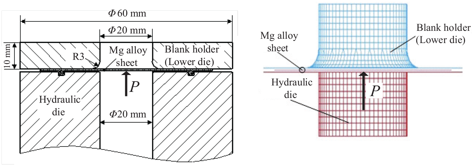
The FEM of magnesium alloy pulsating hydroforming.
Numerical simulation results of magnesium alloy AZ31B under different loading paths
There are two types of loading paths, namely, simple loading path and pulsating loading path, as shown in Figure 2. The purpose of numerical simulation of AZ31B magnesium alloy pulsating hydroforming process is mainly to cooperate with the experimental study, and obtain the deformation state of sheet metal in the arbitrary forming conditions and even in the inadequate experimental conditions at any time, so as to provide sufficient data support for the study on the pulsating hydroforming performance of AZ31B magnesium alloy.
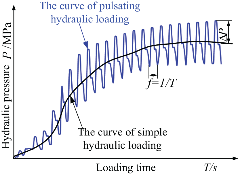
The two types of loading path in magnesium alloy hydroforming.
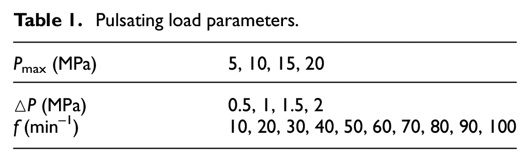
There is a material flow in metal plastic forming. Furthermore, the friction during metal plastic forming is obviously different with mechanical friction. In the numerical simulation, the friction state at the sliding interfaces was assumed to follow the Coulomb friction model that the static friction coefficient between the material and the die and the static friction coefficient between the material and the hydraulic cavity are both taken as 0.1. 10 The pulsating hydraulic bulging process can be approximated as a cyclic process, and the dynamic friction coefficient is 10% of the static friction coefficient. The blank holder force is 2 kN, and the calculation time is 0.02 s. In order to better analyze the forming performance of AZ31B magnesium alloy under pulsating hydraulic loading path, it is necessary to simulate the forming state with different pulsating parameters (amplitude △P, frequency f and reference pressure P0). The simulation conditions are shown in Table 1.
Pulsating load parameters.
In this simulation, the AZ31B magnesium alloy sheet obeyed the Hollomon hardening rule and the Von Mises yield criterion; the relationship of equivalent stress (σe) and equivalent strain (εe) was expressed by σe = Kεen, where K (416 MPa) is the strength coefficient and n (0.2) is the strain hardening index; 17 and the stress strain curves of AZ31B magnesium alloy used in the FE simulations are as shown in Figure 3.
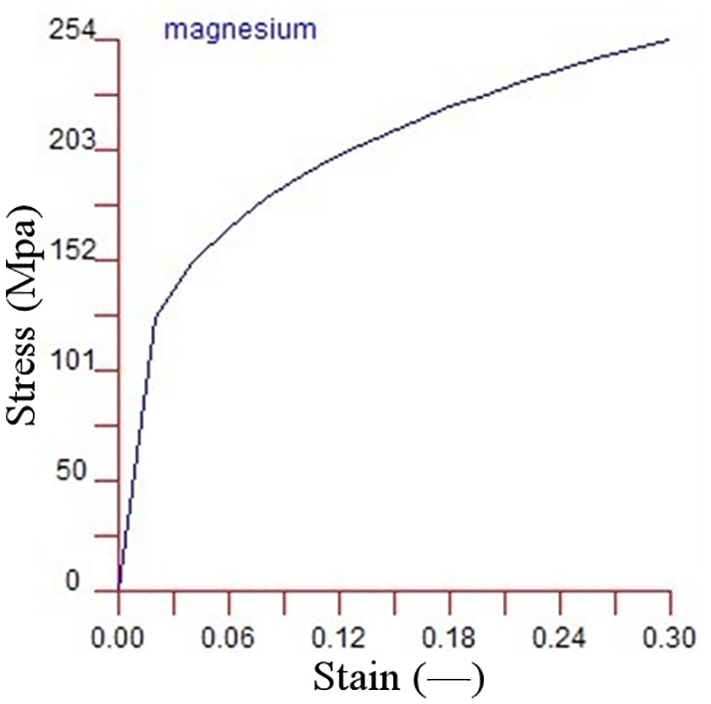
The stress strain curves of AZ31B used in the FE simulations.
The following content is the analysis of the two representative performance indexes, namely, the maximum bulging height and the uniformity of the wall thickness, through the numerical simulation results. Based on simple loading path and pulsating loading path, the forming performance of AZ31B magnesium alloy sheet are shown in Figure 4. And this article takes the middle section node to measure the maximum bulging height, as shown in Figure 5. For better comparison with the experimental results, the measurement will be presented in the following sections.
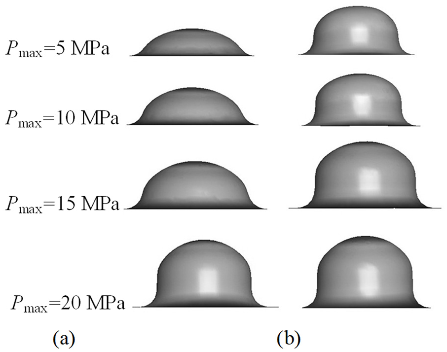
Effect diagram of magnesium alloy forming under two loading paths: (a) simple hydraulic loading and (b) pulsating hydraulic loading.
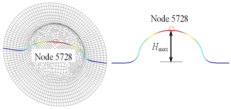
Measurement of maximum bulging height of middle section node.
To reflect the wall thickness distribution of the forming parts under the above two loading paths more accurately and intuitively, the different types of wall thickness distribution from the bottom to the vertex are used for comparative analysis under the same pressure, as shown in Figure 6. And for better comparison with the experimental results, the measurement results will also be presented in the following sections.
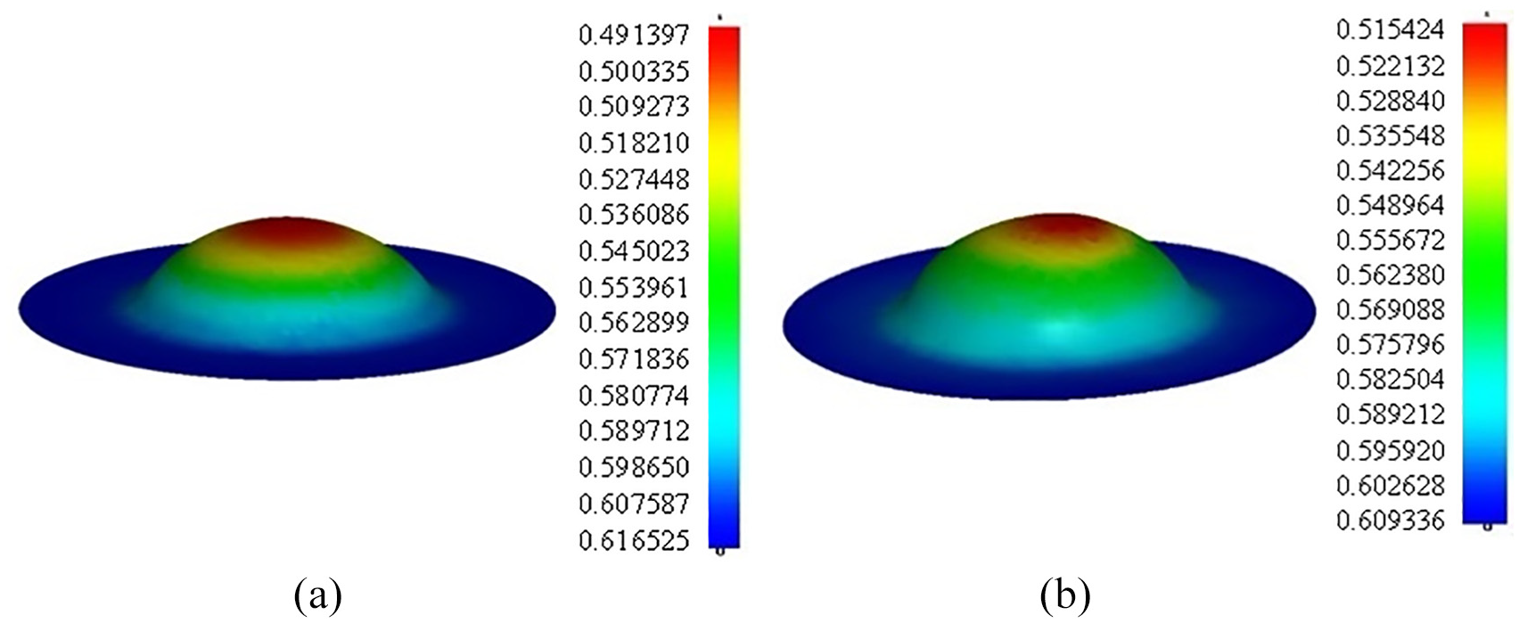
Wall thickness cloud map of simulated parts under different loading paths with the same pressure: (a) simple hydraulic loading path and (b) pulsating hydraulic loading path.
The simulation results show that the wall thickness changes slowly during the pulsating loading in the deformation area of the forming parts, especially in the top area. And the local thinning phenomenon occurs during the simple hydraulic loading; while under pulsating loading, the wall thickness has an uniform transition, and there is no local thinning phenomenon. Therefore, it can be concluded that pulsating loading is more uniform than simple hydraulic loading.
Experimental investigation of magnesium alloy pulsating hydroforming under different deforming parameters
The forming performance indexes, such as wall thickness and bulging height of the nodes corresponding to the numerical simulation, can be obtained from the experimental investigation. And a new evaluation index is proposed to accurately simplify the comprehensive forming performance of magnesium alloy parts with different amplitudes and frequencies.
Experimental device of magnesium alloy pulsating hydroforming
The test device must be able to increase pulsating liquid pressure gradually for sheet forming. The AZ31B magnesium alloy with a thickness of 0.6 mm was used in the test, and the range of hydraulic pressure required for forming is from 3 to 25 MPa, so the test device must have good sealing performance during the process. And the working diagram of pulsating hydroforming device is shown in Figure 7.
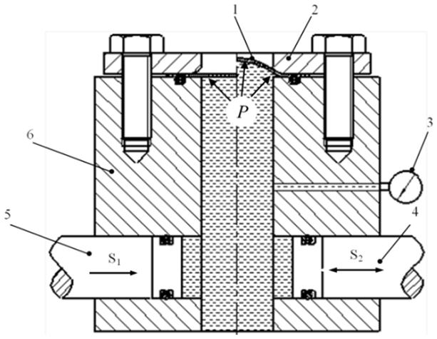
Schematic diagram of pulsating hydroforming device. 1. AZ31B magnesium alloy, 2. blank holder, 3. pressure gauge, 4. piston rod S2, 5. piston rod S1 and 6. hydraulic die.
According to schematic diagram, the process of pulsation liquid pressure generation is shown as follows: in the hydraulic chamber of the forming mold, when the two moving piston rods S1 and S2 are set, the piston rod S1 is pushed by external forces for linear movement, squeezing the liquid in the cavity and increasing liquid pressure P1 gradually. At the same time, the piston rod S2 is pushed by external forces for reciprocating motion to squeeze the liquid in the hydraulic die and produce alternating pulsating fluid pressure P2. Through the external power structure and power connection, the two piston rods are controlled to move simultaneously, so that the obtained two hydraulic pressures P1 and P2 are superimposed on each other, and thus, the gradually increasing pulsation hydraulic pressure P0 can be obtained, as shown in Figure 8.
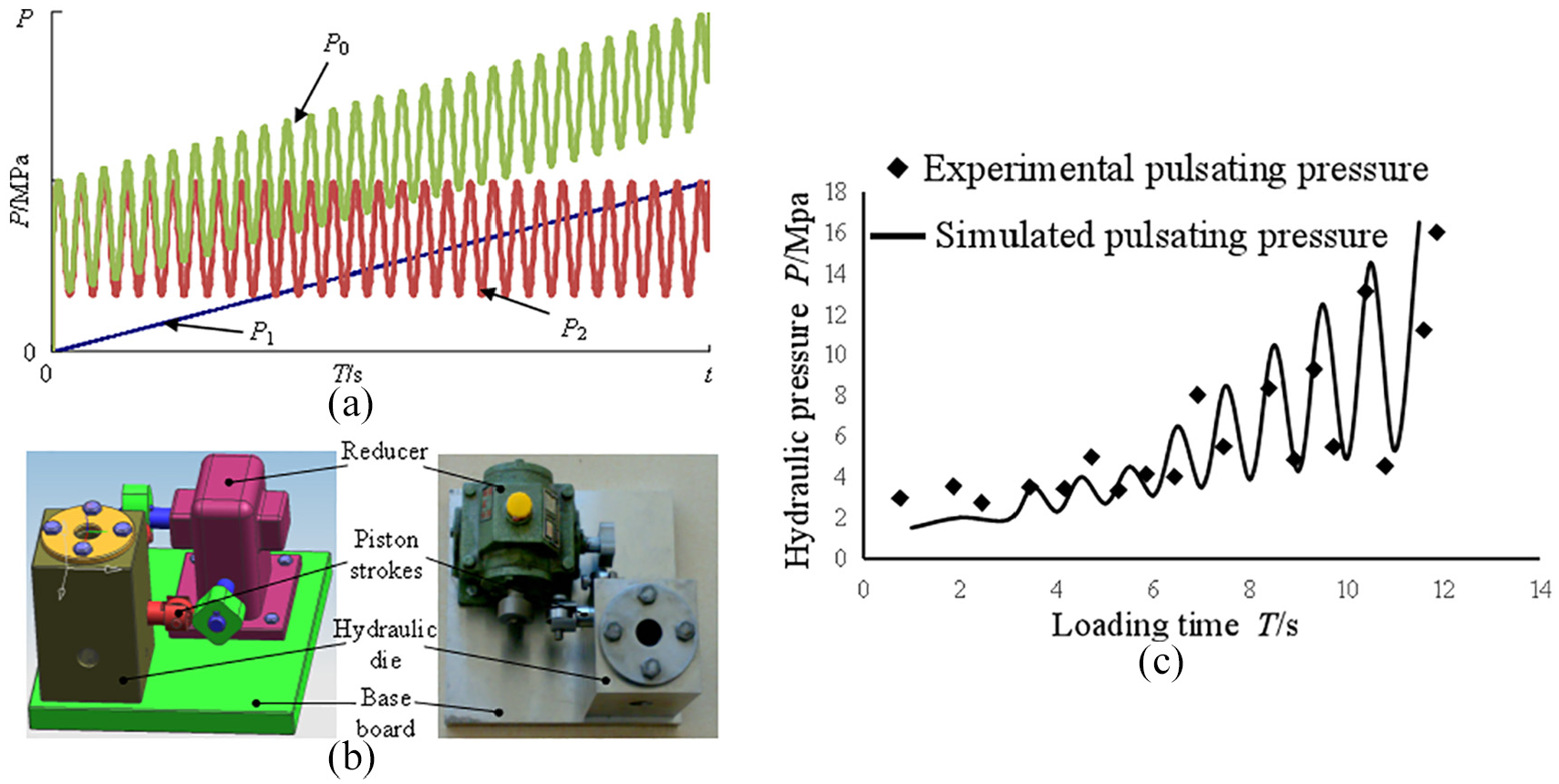
The pulsating liquid pressure produced by the superposition: (a) schematic diagram for experimental pulsating pressure, (b) experimental pulsating pressure generating device and (c) experimental and simulated pulsating pressure.
Experimental investigation of magnesium alloy AZ31B under different loading paths
The loading parameters in the experiment are consistent with that in the numerical simulation. In the hydraulic forming test of AZ31B magnesium alloy with simple hydraulic loading and pulsating hydraulic loading, the hydraulic die was filled with liquid; the slab was put in place; the blanking force of the blanking ring with dial torque wrench was adjusted appropriately; and the overflow valve pressure values of the hydraulic control system were set as 5, 10, 15 and 20 MPa, respectively. The thickness of the AZ31B magnesium alloy in the experiment was 0.6 mm, and the forming parts were measured by the CL5 ultrasonic electronic thickness gauge produced by Kraut Kramer in Germany, as shown in Figure 9. The dial type vernier caliper was used to measure the maximum bulging height of the forming parts. The above measuring accuracy is ±0.02 mm, which can meet the accuracy requirements of the required data.
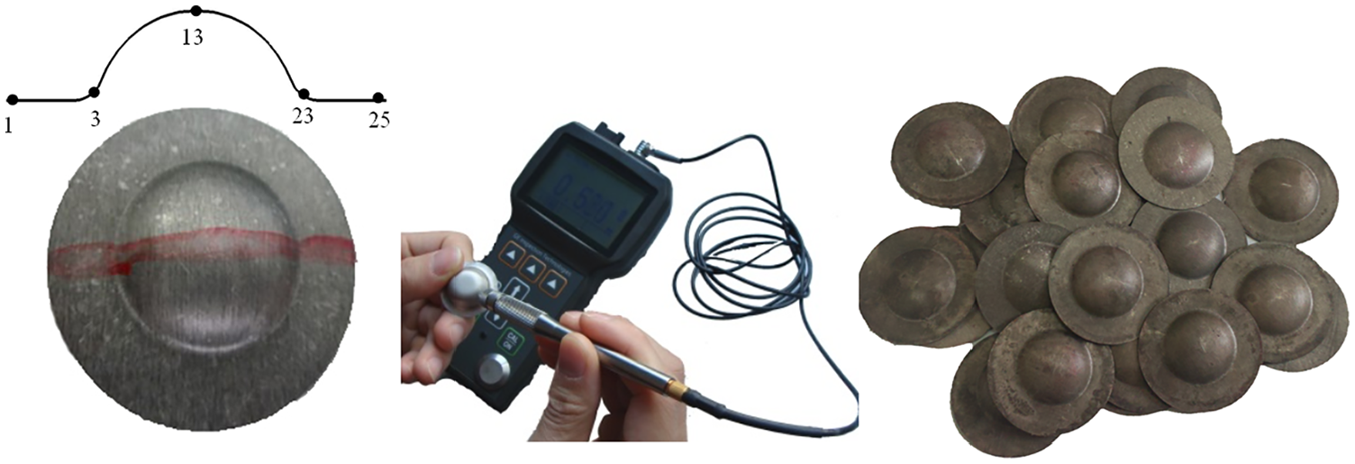
Measurement of wall thickness of formed parts.
Figure 10 shows the change of the maximum bulging height Hmax of magnesium alloy with the maximum liquid pressure Pmax under the simple loading path and the pulsating loading path. As shown in Figure 10, when the corresponding maximum liquid pressure Pmax is set as the same in both two loading paths, compared with simple loading with the condition of Pmax < 20 Mpa, pulsating loading can obtain a larger maximum bulging height Hmax.
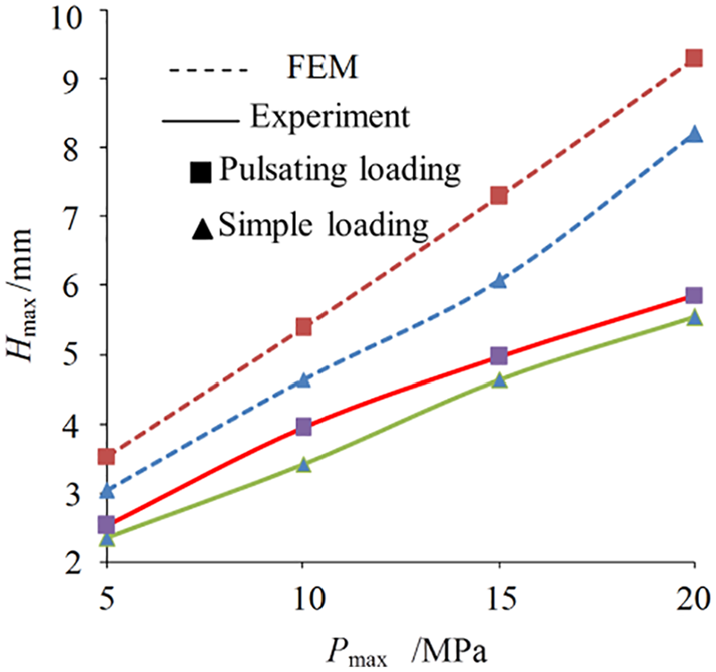
Variation curve of the Hmax of formed parts under two loading paths.
When the maximum liquid pressure Pmax is 15 MPa, the maximum bulging height obtained by pulsating loading and simple loading are 4.96 and 4.36 mm, respectively, and the maximum bulging height obtained by pulsation loading could be increased by 13.8%, compared with that obtained by simple loading. In the numerical simulation results, the maximum bulging height obtained by pulsation loading and simple loading are 7.25 and 6.07 mm, respectively, and the maximum bulging height obtained by pulsation loading is 17.7%, which is higher than that by simple loading. Due to the more accurate requirement of experiment tools and measuring equipment, such as pulsating hydraulic generators, the experimental results may deviate from the simulation results.
Figure 11 shows the wall thickness distributions of the middle section of magnesium alloy sheet under simple loading path and pulsating loading path. It can be observed from Figure 11 that the wall thickness distribution curve of the middle section is similar to that of the bulging profile, indicating that there is a certain relationship between the thickness change of the forming parts and the bulging height. The results from experiment and numerical simulation show that the wall thickness changes slowly during the pulsating loading in the deformation region of the forming parts, especially in the top region, and the local thinning phenomenon occurs during the simple loading path. However, the wall thickness has an uniform transition under pulsating loading. And there is no local thinning phenomenon, demonstrating that pulsating loading is more uniform than simple loading. Furthermore, the wall thickness value under simple loading is higher than that under pulsating loading, because under the same maximum liquid pressure, its sheet deformation is larger; its expansion is more complete; and its ultimate forming capacity is improved.
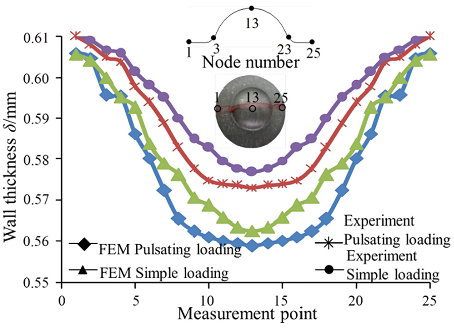
Wall thickness distribution of magnesium alloy under two loading paths.
The influence of pulsation parameters on deformation behavior of magnesium alloy
The influence of pulsation amplitude and pulsation frequency on forming performance (maximum bulging height and wall thickness uniformity) of AZ31B magnesium alloy sheet is studied by numerical simulation analysis and experimental study. Applying the wall thickness difference Δδ (maximum wall thickness δmax – minimum wall thickness δmin), the calculation method of wall thickness uniformity can be done.
Effect of amplitude and frequency on maximum bulging height
The variation of maximum bulging height Hmax with amplitude △P is shown in Figure 12. As shown in Figure 12, for the four groups of different maximum liquid pressure Pmax with the same frequency f (f = 10), their influence of amplitude △P on the maximum bulging height Hmax are similar, meaning that the maximum bulging height decreases nonlinearly and slowly when increasing the amplitude. When the maximum liquid pressure Pmax is 15 MPa, the maximum bulging heights Hmax under the two amplitudes (△P = 0.5 and 2 MPa) are 7.481 and 7.105 mm, respectively, and the former one is 5.29% higher than the latter one. In other words, in the process of AZ31B magnesium alloy pulsating hydroforming, a relatively small amplitude can form a larger maximum bulging height, which can improve the ultimate forming capacity of the sheet to a certain extent.
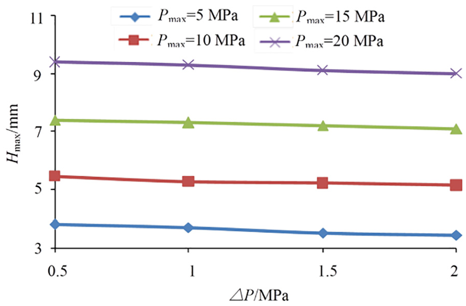
Effect of amplitude on maximum bulging height.
Pulsation frequency f refers to the number of times that the liquid pressure P repeatedly impacts the sheet with △P (namely, the pulsation cycle times) when the liquid pressure P increases from zero to the maximum liquid pressure Pmax. During the forming process, the larger f is, the higher frequency the pulsation liquid pressure impacting the sheet is. Figure 13 shows the influence of frequency f on the maximum bulging height Hmax. As can be seen from Figure 13, under the same amplitude and maximum liquid pressure, the maximum bulging height changes in a wave-like shape with the increase of the frequency f. When f is less than 50 times, the maximum bulging height increases nonlinearly, and when it is equal to 50 times, the maximum bulging height reaches the maximum. In addition, when f is more than 50 times, the maximum bulging height is nonlinear and decreases slowly to a stable range. For different amplitudes, the influence of frequency f on the maximum bulging height is consistent, and the maximum bulging height obtained at frequency f = 50 times is the maximum, regardless of the value of amplitude.
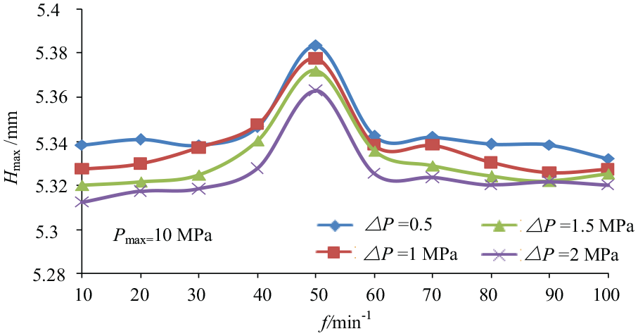
Effect of frequency on maximum bulging height.
Effect of amplitude and frequency on wall thickness uniformity
Without wrinkling failure and rupture failure conditions, magnesium alloy AZ31B sheet pulsating hydroforming parts of wall thickness uniformity can be represented with a wall thickness difference. The smaller Δδ means that wall thickness between each part area is closer and that the uniformity of the forming part is better. Figure 14 shows that the wall thickness difference of Δδ changes with the amplitude △P under different maximum liquid pressure Pmax. As shown in Figure 14, the effects of amplitude on wall thickness uniformity are similar with four different sets of maximum liquid pressure Pmax and with the same frequency f, that is, the wall thickness difference is nonlinear and can be slowly reduced when increasing the amplitude. It shows that a greater amplitude is more useful to obtain wall thickness uniformity, in other words, taking a larger amplitude can improve the wall thickness uniformity of the forming part to some extent in other conditions.
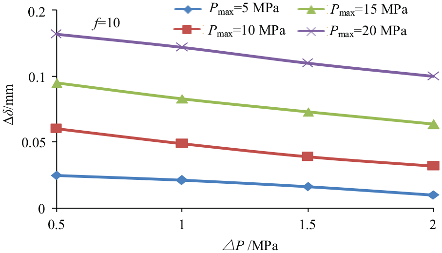
Effect of amplitude on wall thickness difference.
Under the same maximum liquid pressure Pmax, wall thickness difference Δδ changing with the frequency f is shown in Figure 15. As Figure 15 shows, under the same maximum liquid pressure Pmax with different amplitudes, the influence of frequency f on wall thickness difference is unchanged. When frequency f < 60, the wall thickness difference nonlinearly gradually reduces, but when frequency f > 60, the wall thickness difference is nonlinear and increase slowly, and the change is quite gentle, namely, the wall thickness uniformity of the forming parts remains unchanged. This indicates that with the larger the frequency f (f < 60), the wall thickness uniformity of the forming part is better. In other words, when other conditions have been determined, the wall thickness uniformity of forming parts with a larger frequency f is better.
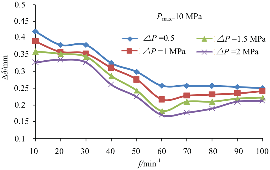
Effect of frequency on wall thickness difference.
Determination of reasonable pulsating forming parameters
From what has been discussed above, in the actual processing, it is always expected that the forming parts have larger bulging height and better wall thickness uniformities. When determining the maximum bulging height of a set of pulsation parameters (amplitude △P and frequency f), it can be selective to obtain a larger maximum bulging height, while the uniformity of wall thickness is not optimal. Therefore, a new index needs to be proposed to consider the maximum bulging height and wall thickness uniformity. In order to obtain reasonable pulsating forming parameters, the forming parts shall have larger maximum bulging height and better wall thickness uniformity, that is, the sheet metal shall have a better comprehensive forming performance. Therefore, we propose a new evaluation index k for forming performance
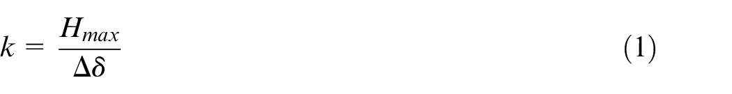
The new evaluation index k is more effective, which means that the biggest bulging forming height Hmax or wall thickness difference Δδ are smaller, and the wall thickness uniformity and the forming performance of magnesium alloy sheet are better. According to the previous analysis results, the influence of amplitude and frequency on the maximum bulging height and wall thickness uniformity is unchanged under different maximum liquid pressure. Therefore, when determining reasonable pulsating forming parameters, the data obtained under any group of maximum liquid pressure can be selected as the research object. For example, when the maximum liquid pressure Pmax = 10 MPa with different amplitudes △P and frequency f, the k value obtained is shown in Figure 16. We can learn from Figure 16 that k reaches the maximum value when the amplitude △P = 2 MPa and the frequency f = 60 times. This indicates that compared with the pulsation parameters of other combinations, AZ31B magnesium alloy sheet has the best comprehensive forming performance under the pulsation parameters (△P = 2 MPa, f = 60). Therefore, this set of pulsation parameters (△P = 2 MPa, f = 60) is selected as the best forming parameters for the pulsation hydroforming of AZ31B magnesium alloy sheet.
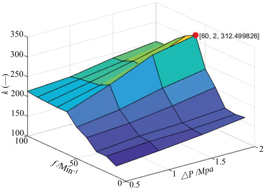
The example of k values with different amplitudes and frequencies under specified maximum pressure.
Conclusion
According to the numerical simulation and experimental results, we make a comparison of AZ31B magnesium alloy sheet under the simple loading and the pulsating loading, and discuss the pulsating parameters (amplitude and frequency) effect on the deforming properties of AZ31B magnesium alloy sheet. Based on the above work, we further propose a new forming performance evaluation index k with a simple example preliminarily determining the best forming parameters of AZ31B magnesium alloy sheet under pulsating hydroforming. In addition, we find that compared with simple loading, the maximum bulging height and wall thickness uniformity of the formed part obtained by pulsating loading are larger under the same maximum liquid pressure, which can effectively improve the forming performance of AZ31B magnesium alloy sheet. Pulsating hydroforming can improve the forming performance of AZ31B magnesium alloy sheet, which is due to the effect of the intermittent cycle of the pulsating liquid pressure. With the conditions of a certain amplitude and frequency, the flow resistance can be greatly reduced by the influence of sheet metal flange area, making the sheet deformation effectively have material supplement and take shape more advantageously. Under the same maximum liquid pressure and frequency, when amplitude is larger, the maximum bulging height is smaller, and the uniformity of the wall thickness is better. What is more, under the same maximum liquid pressure and amplitude, the influence of frequency on the maximum bulging height is undulating, and the maximum bulging height obtained is the largest when the frequency f is equal to 50. And the higher the frequency is, the wall thickness uniformity is better. However, when the frequency is satisfying the condition of f > 60, the wall thickness uniformity will no longer change with the frequency. When the pulsation parameters (amplitude △P = 2 MPa and frequency f = 60) are selected as the optimal forming parameters for AZ31B magnesium alloy sheet pulsating hydroforming, the k value is the largest. The above conclusions can prove that the formability of AZ31B magnesium alloy is better under the condition of pulsating hydraulic loading. By finding the right amplitude and frequency, the forming parts will have good bulging heights and uniform wall thicknesses.
Footnotes
Acknowledgements
We would like to thank Professor Liu Zheng of Jiangxi University of Science and Technology for giving a lot of guidance and help.
Declaration of conflicting interests
The author(s) declared no potential conflicts of interest with respect to the research, authorship, and/or publication of this article.
Funding
The author(s) disclosed receipt of the following financial support for the research, authorship, and/or publication of this article: This work was financially supported by National Natural Science Foundation of China (51665018) and Youth Scientific Research Project of JXEDU (GJJ171265).