
Abstract
To effectively reuse existing numerical control machining process of similar feature, a novel numerical control machining process reuse approach by merging feature similarity assessment and data mining for computer-aided manufacturing models is proposed. First, a feature-based numerical control machining process model is proposed to formalize the links between machining feature and its associated machining operations. Based on feature-based numerical control machining process model, the machining know-how database is automatically generated through data mining for existing computer-aided manufacturing models. Then, an effective numerical control machining process reuse–enabled feature similarity assessment approach is presented to locate the similar features. Moreover, two numerical control machining process reuse modes are explored to reuse the associated machining operations of the selected similar feature. Finally, a prototype system based on CATIA has been developed to verify the effectiveness of the proposed approach.
Keywords
Introduction
With the extensive applications of computer-aided design (CAD)/computer-aided manufacturing (CAM) systems in manufacturing industries, a vast number of three-dimensional (3D) CAD models with numerical control (NC) machining processes (aka CAM models) have been generated. 1 According to the statistics, 2 in product design, only 20% of parts require completely new designs, while 40% of them are obtained by direct reuse and another 40% through a modification of the existing designs. This characteristic also exists in part manufacturing stage. In matured manufacturing enterprises, similar features are cut with similar NC machining processes, which indicate that there exists a large amount of NC machining processes that can be reused. 3 The current method of generating machining operations with commercial CAM software requires tedious user interactions. Cutting tool, drive geometries, and machining strategy parameters must be selected and defined manually. 4 Repetitive workload for similar features causes low efficiency of NC machining process generation. Therefore, reusing the process parameters of similar feature embedded in successful CAM models to generate the machining operations of query feature automatically will provide an effective way to decrease the number of user interactions and reduce the time for machining preparation, 5 and it will be able to greatly facilitate new part manufacturing.
Since machining features could capture machining process information effectively, feature-based approach is the most attractive topic in machining process planning. Here, feature recognition is used to generate machining features and plays a key role in achieving CAD/CAM integration. 6 The feature recognition approach examines the topology and geometry of a part and matches them with the appropriate definition of predefined features. Many research works have been published in the field of feature recognition, and various approaches have been adopted.7–9 However, the existing feature recognition technologies mainly focus on analyzing the geometric information of the mechanical part, ignoring the technological information (e.g. dimension, tolerance, roughness) to the impact of feature recognition, 10 and the machining features with free-form surfaces or interacting machining features with multiple interpretations are still difficult to handle.
Over the years, various feature-based machining process reuse technologies are presented, which have been widely used in manufacturing industry, such as group technology, 11 feature template technology, 12 and case-based process design technology. 13 Zhang et al. 12 presented a method based on feature machining templates to realize the integration of CAD/computer-aided process planning (CAPP)/CAM for marine diesel key components based on feature similarity evaluation, and this method could reduce repetition works in machining process design and enhance the generality of the integrated CAD/CAPP/CAM systems. Yan et al. 14 and Zhang et al. 15 presented a similar approach to recognize machining features from existing NC programs to reuse the associated machining operations, and the method has been applied to simple features. Jiang et al. 16 introduced a methodology of tool selection for die and mold NC machining. They employed a fuzzy similarity-based rough set algorithm in feature weighting and reduction for case-based reasoning systems. Mawussi and Tapie 17 presented a machining process model for complex forging die machining to decrease the time for machining preparation by formalizing the links among information imbedded in the machining features and the parameters of cutting tools and machining strategies. Wang et al. 18 presented a feature-based and agent-driven NC tool path generation approach to respond timely to the design and machining process changes during the production course, in which machining features are activated by agents to make the proper responses for updating the tool path automatically. However, the research on feature-based machining process reuse is still in its infancy, especially for NC machining process reuse. They need the support of experts to construct the machining know-how database in advance. In addition, the similar features are searched manually, and their successful machining processes are always reused manually. 19
From the analysis above, current existing CAM models cannot be handled by computers for NC machining process reuse directly with these existing methods due to the following problems: (1) lack of feature-based structured representation approach for CAM model to generate the machining know-how database automatically, (2) there is no effective NC machining process reuse–enabled feature similarity assessment approach to locate the similar features, and (3) the NC machining process reuse modes are absent. Therefore, it will be a huge waste for the enterprises if the CAM models, together with the embedded machining know-how, could not be discovered and exploited to help practical works.
In this article, an effective NC machining process reuse approach by merging feature similarity assessment and data mining for CAM models is proposed to overcome the above-mentioned problems. First, a feature-based NC machining process model is proposed to formalize the links between machining feature and its associated machining operations. Then, the reusable NC machining process parameters are extracted via data mining for existing CAM models guided by feature-based NC machining process model, and the machining know-how database is generated accordingly. In addition, a multilevel feature descriptor capturing different levels of information for machining process planning is designed to establish the machining feature similarity assessment model. Finally, for the selected similar features, two reuse modes, including direct and revised reuse, are explored to meet different NC machining process generation requirements in terms of feature similarity assessment results. The work presented is devoted to the machining of mechanical parts cut with 2.5-axis computer numerical control (CNC) milling.
Basic concepts and overview of our approach
Basic concepts
In order to effectively reuse the NC machining process parameters embedded in the CAM models, a feature-based NC machining process model is first introduced.
Definition 1: feature-based NC machining process model (MFP)
The MFP is a feature-based data model to formalize the links between machining feature and its associated machining operations. MFP can be denoted as
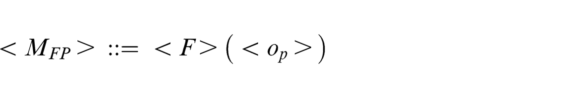
where F is a machining feature and op is a machining operation.
Definition 2: machining feature (F)
A machining feature is a set of adjacent faces associated with a set of machining operations. Some machining attributes (i.e. cutter orientation, precision constraint, and reasonable machining strategy) should be satisfied to generate a machining feature. F can be denoted as
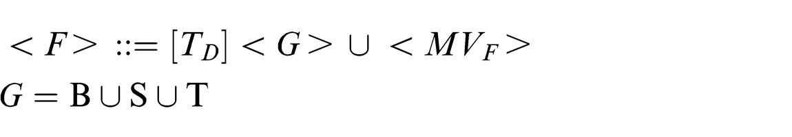
where TD is the technological data associated with F (e.g. material, tolerance, surface roughness); G is the constraint geometry, including bottom face (B), side faces (S), and top face (T); and MVF is the machining volume of F.
Definition 3: machining operation (op)
A machining operation is generated with the parameters of machining strategy (MS), cutting tool (T), and drive geometry (DG), corresponding to a machining element (Me). op can be denoted as
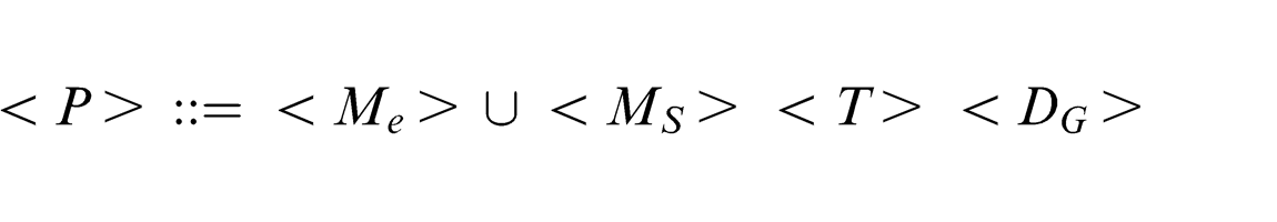
where Me is the machining volume of op.
An inclusion relationship exists between MVF and Me, and MVF is composed of n machining elements, denoted as
Figure 1 shows the structural framework of feature-based NC machining process model. The relationship between machining feature and machining operation is one-to-many. The NC machining process of a part can be regarded as the optimization and combination of multiple feature machining process cases. To reuse the process parameters in the repository, the associations between machining features and machining operations embedded in the CAM models need to be established according to Definition 1.
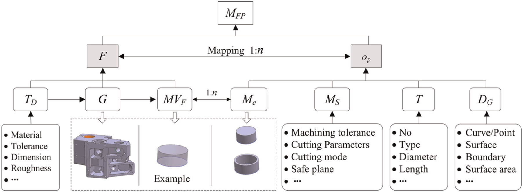
Structural framework of feature-based NC machining process model.
Overview of our approach
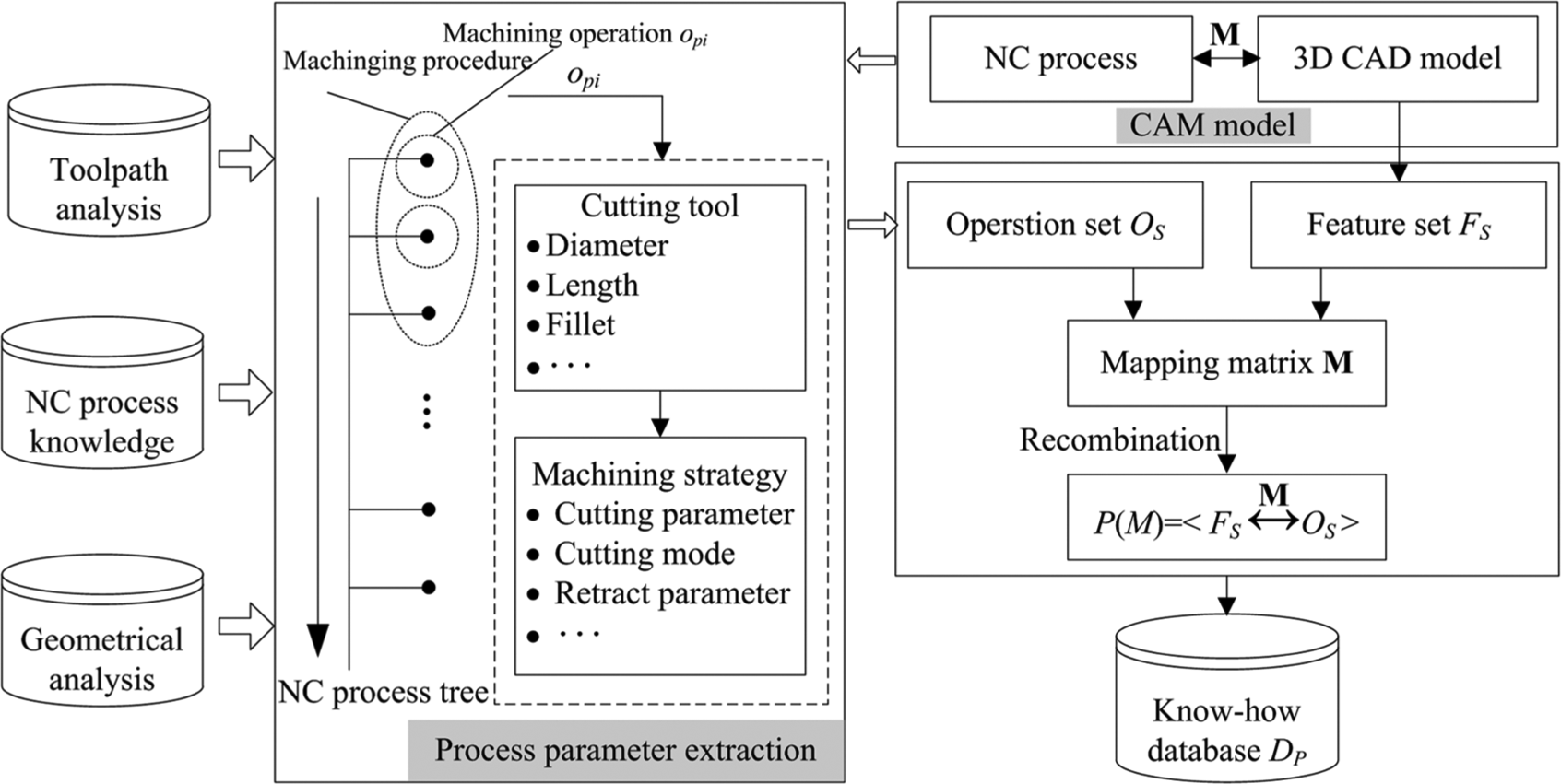
The systematic overview of our approach for NC machining process reuse is described in Figure 2. It could be seen that our approach contains four main steps: (1) machining feature recognition, (2) data mining for CAM models, (3) machining feature similarity assessment, and (4) NC machining process reuse. Here, a brief description of each step is given:
Machining feature recognition. In this step, the machining features of the existing part and the new part are all obtained automatically with the feature recognition algorithm proposed in Huang et al. 10
Data mining for CAM models. According to the recognized machining features of the existing part, data mining for CAM models is carried out to extract the reusable process parameters and generate the machining know-how database automatically in terms of MFP. In this step, the machining operations associated with a given machining feature are clustered.
Machining feature similarity assessment. This step realizes machining feature similarity assessment merging with machining semantics and returns the similar features, which have similar geometry, topology, and machining semantics to the query feature, to the user.
NC machining process reuse. According to the feature similarities, different NC machining process reuse modes can be selected to generate the machining operations of query feature automatically through reusing the process parameters (e.g. MS, T, DG) of similar feature or to inspire the user to design the machining operations of query feature.
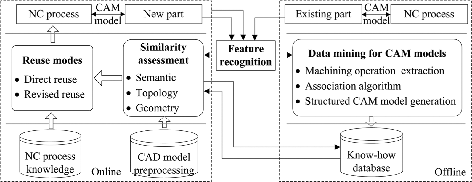
Systematic overview of NC machining process reuse approach for similar features.
Data mining for CAM models
In general, a machining feature is machined with several machining operations, and a machining operation can probably cut multiple machining features meanwhile. It means that the machining operations associated with a machining feature are always distributed in the CAM model.
Data mining for CAM models in terms of machining features is mainly divided into two main steps: (1) association between machining features and machining operations and (2) feature-based structured CAM model generation. Next, detailed descriptions of the two steps are given.
Association algorithm between machining features and machining operations
Definition 4: feature association
Given a machining feature F and its machining volume MVF, if there exists a cutter location (CL) point pi generated by machining operation op located in MVF, that is,
In general, there are two ways to establish the association between machining features and machining operations. One way is to construct the machining volume of the machining feature. However, the machining volume construction for the complex machining feature is time-consuming. The other way is to recognize machining features from existing NC programs like in Yan et al. 14 However, it is only suitable for simple non-interacting machining features. Therefore, in order to improve the validity and efficiency of the association method between machining feature and its associated machining operations, an association method by computing the projection points of the CL points on the faces of the machining feature is presented.
Given a machining feature F and a machining operation op of the CAM model, where fB is the bottom face and S is the side face set. The tool path generated by machining operation op is composed of n CL points, denoted as op = {pi}, 1 ≤i≤n. For an arbitrary CL point pi (pi∈op), if fB is not null, compute the projection point p of pi on fB. If p meets the condition p∈fB,
According to the type of F, establish the association between op and F (detailed in Algorithm 1):
Case 1. F is a facing feature, that is, S is null. If bool(fB) is true, op is associated with F.
Case 2. F is a profile feature, that is, fB is null. If bool(fS) is true, op is associated with F.
Case 3. F is a pocketing feature, that is, fB and S are all not null. If both bool(fB) and bool(fS) are true, op is associated with F.
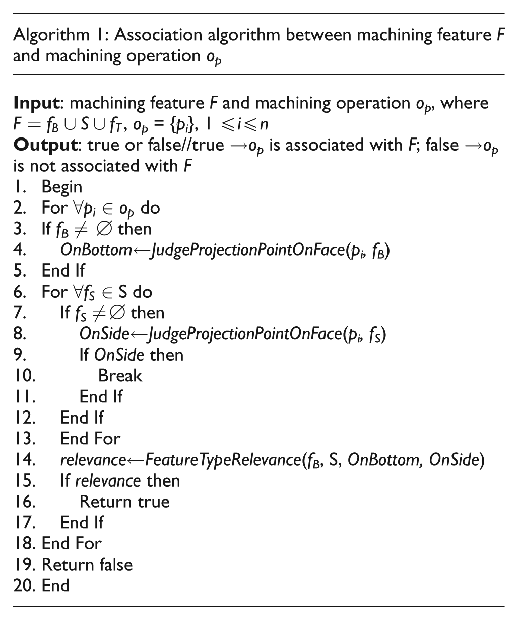
Figure 3 shows a feature association example, and Figure 3(b) is the tool path generated by machining operation op. Since fB and S are all not null, machining feature F is a pocketing feature (Figure 3(a)). It can be seen from Figure 3(b) that the projection points of the CL point pi on bottom face fB and side face fS are p1 and p2, respectively. Although p1∈fB and p2∈fS, p1 and p2 do not meet the above constraints. Therefore, the association between op and F cannot be established from pi. In contrast, CL points pj and pk meet the constraints for fB and fS, respectively. Therefore, op is associated with F, and the extracted process parameters of op are shown in Figure 3(c).
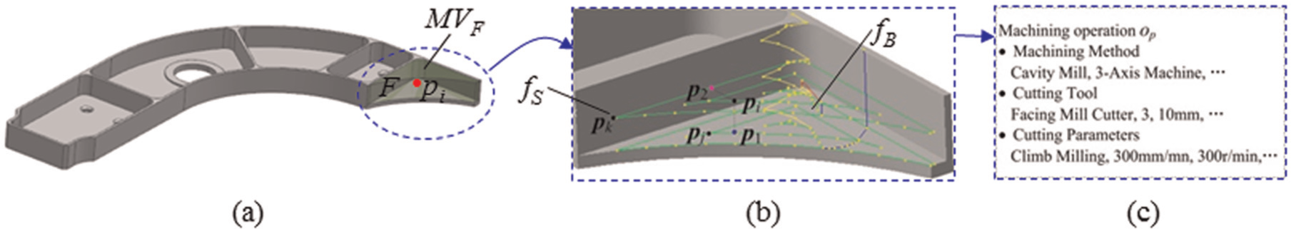
Example of feature association: (a) feature association, (b) tool path, and (c) process parameters.
Feature-based structured CAM model generation
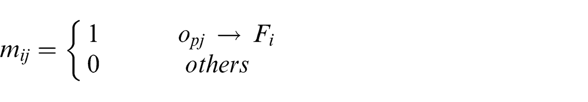
According to the association algorithm presented above, all machining operations associated with a given machining feature are clustered. For a CAM model, the associations between machining features and machining operations can be represented with a mapping matrix.
Definition 5: mapping matrix
Given a set of machining features, FS = {Fi}, 1 ≤i≤n, and machining operations, OS = {opi}, 1 ≤i≤m, of the CAM model M, where OS is a partial order set. The mapping matrix of model M is
Based on the mapping matrix
The key steps of data mining for CAM model are given as follows (Figure 4):
Step 1. Recognize the machining features of M, denoted as FS = {Fi}, 1 ≤i≤n;
Step 2. Traverse the machining operations of M, denoted as OS = {opi}, 1 ≤i≤m;
Step 3. Initialize the mapping matrix
Step 4. For i = 1, 2, ..., n, do the following:
Step 4.1. For j = 1, 2, ..., m, do the following:
According to Algorithm 1, establish the association between machining feature Fi and machining operation opj:
If opj→Fi then
mij = 1
End If
j = j+1;
Step 4.2. i = i+1;
Step 5. Construct a machining process model case
Flow chart of data mining for CAM models.
Feature similarity assessment merging with machining semantics
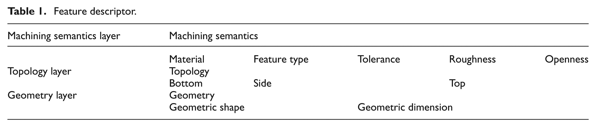
In order to effectively achieve feature similarity assessment merging with machining semantics, a reasonable and comprehensive feature descriptor involving various levels of data from high-level information like machining semantics to low-level information like geometric shape is a prerequisite. Table 1 shows the feature descriptor constructed in this article.
Feature descriptor.
For each element of the descriptor representing different contents, each element needs to follow its own rule to compute its similarity.
Machining semantics layer
This layer represents the essential machining properties of the machining feature, and it mainly contains material, machining feature type, machining requirements, and so on.
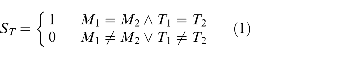
Material/machining feature type
The material and machining feature type have the one-vote veto characteristic. As long as the material or the machining feature type is different between the two machining features, the similarity of the two machining features is set to 0. If both of them are the same, the similarity of the material and the machining feature type is 1.
Suppose that the material and the machining feature type of the two machining features are M1 and M2, T1 and T2, respectively, and the similarity of the material and the machining feature type is denoted as ST, then
Tolerance/roughness
In the process of NC machining process planning, both the tolerance and roughness are closely related to the machining operation parameters of a machining feature. For example, given two machining features with the same geometric shape, if they have different dimensional accuracy, the machining processes may be quite different. Here, the similarity assessment for tolerance and roughness depends on the supreme dimensional tolerance grade and the minimum roughness value, respectively. It can be denoted as SR, then
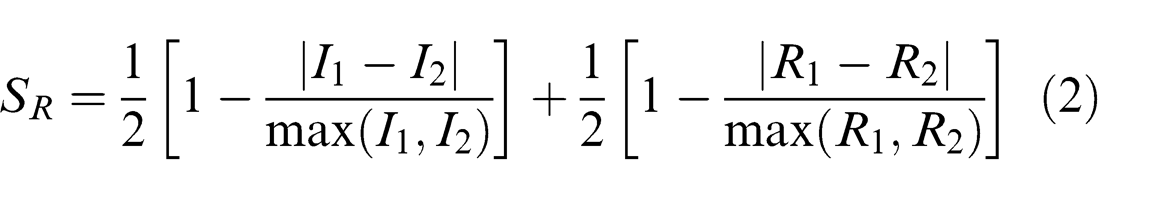
where I1 and I2 are the supreme dimensional tolerance grades of the two machining features and R1 and R2 are the minimum roughness values of the two machining features.
Openness
The openness of a machining feature is very valuable information for the cutting tool selection, and it should be considered in feature similarity assessment. In general, the openness depends on the machining feature types. For instance, the pocket depends on the cutting tool radius domain, and the hole depends on the diameter/depth ratio.
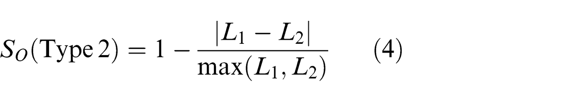
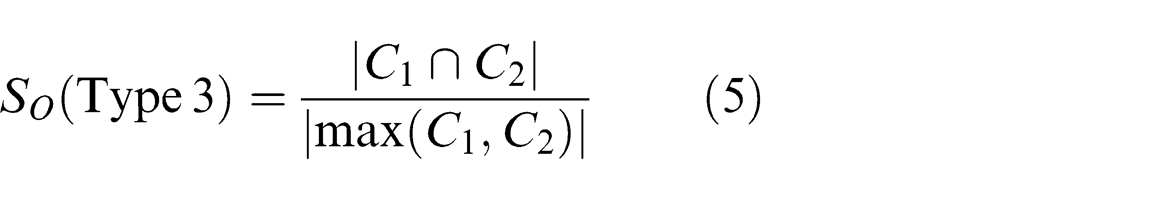
The following gives the major rules for the openness similarity assessment, SO, in terms of machining feature types:
Type 1. For a pocket, the medial axis transform algorithm 20 is used to compute the cutting tool radius domain in each machining stage
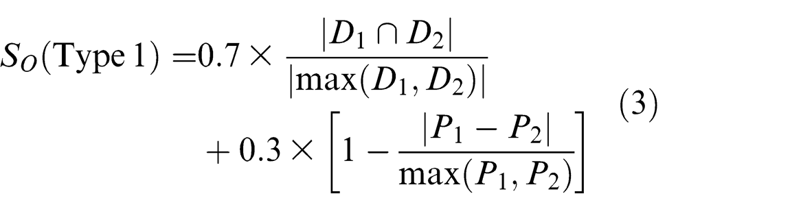
where D1 and D2 are the cutting tool radius domains of the two machining features in rough machining stage and P1 and P2 are the maximum cutting tool radiuses in finish machining stage.
Type 2. For a hole, the diameter/depth ratios of the two holes are computed, denoted as L1 and L2
Type 3. For a free-form surface, the curvature radius domains of the two free-form surfaces are computed, denoted as C1 and C2
Topology layer
To describe the topology properties of a feature, some definitions related to graph theory are given as follows.
Definition 6: common sub-graph
Given graphs G, Gα, and Gβ, if there exists sub-graph isomorphism from G to Gα and from G to Gβ, then G is a common sub-graph of Gα and Gβ.
Definition 7: maximal common sub-graph
Given graphs Gα and Gβ, if graph G is a common sub-graph of Gα and Gβ, and there exists no other graph G′ of Gα and Gβ that has more nodes than G, then G is called the maximal common sub-graph of Gα and Gβ.
Topology layer information is used to describe the structure of a machining feature and the relative location relations among the machining faces. It can be expressed by a face attributed adjacency graph (FAAG), denoted as G = (V, E) (Figure 5), which has the local characteristics, where V is a vertex set corresponding to the machining faces of a machining feature and E is an edge set corresponding to the adjacency relations between the machining faces. The attributes of the vertex include the machining face geometric type (e.g. planar, cylinder, and free-form surface), attributed type (e.g. bottom, side, and top), and convexity; the attributes of the edge include the edge convexity, edge type (e.g. line, arc, and spline), and the included angle between adjacency faces. As shown in Figure 5(b), f3 is a bottom face, f1 and f5 are two side faces, f2 and f4 are two fillet faces, also belonging to side faces, and e12 is a concave tangent line edge.
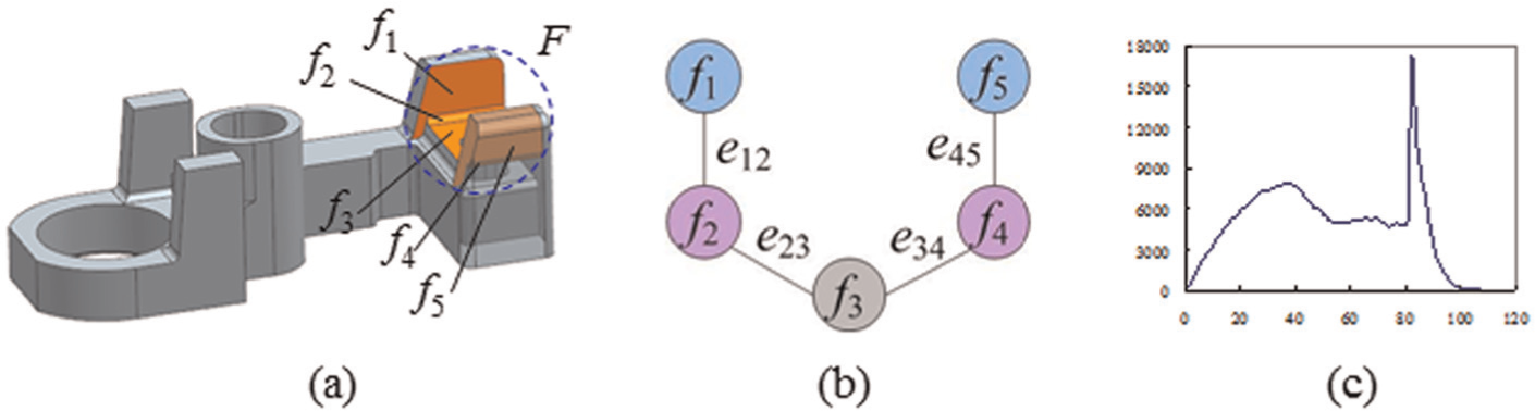
Face attributed adjacency graph of feature F: (a) CAD model, (b) FAAG of F, and (c) D2 shape distribution.
If two machining features are similar in topological structure, there exists a common sub-graph between their FAAGs. Conversely, the similarity of the topological structure can be calculated by detecting the maximal common sub-graph. A heuristic algorithm 21 is used to detect the maximal common sub-graph of the two machining features.
Suppose that the FAAGs of the two machining features are G1 and G2, respectively, and the similarity of the topological structure is denoted as SG, then
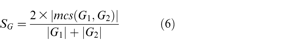
where function |•| returns the number of nodes and mcs(G1, G2) returns the maximal common sub-graph of G1 and G2.
Geometry layer
Geometry layer represents the geometric information of a machining feature from a macro perspective. It contains geometric shape and geometric dimension. The geometric information represents the global characteristics and acts as supplementary information.
Geometric shape
D2 shape descriptor is used to represent the machining feature geometric shape for its invariant to rotation and scale transformations and high performance in this work. An exhaustive survey of D2 shape descriptor can be found in Osada et al. 22 Figure 5(c) shows an example of a machining feature’s D2 shape distribution.
Suppose that the D2 shape distributions of the two machining features are H1 and H2, respectively, and the earth mover’s distance (EMD) is used to assess the two shape distributions. The similarity of the geometric shape is denoted as SD, then
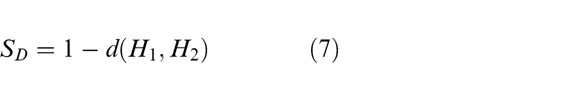
where function d(.) returns the EMD distance between H1 and H2.
Geometric dimension
Geometric dimension used in this article includes axial dimension and radial dimension. The axial dimension represents the machining depth of a machining feature, and the radial dimension represents the machining breadth of a machining feature. The similarity of the geometric dimension SQ is calculated using the machining feature’s minimum bounding box, then
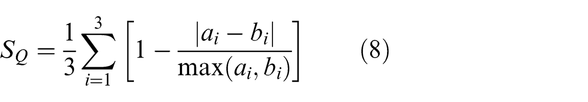
where a1, a2, a3 and b1, b2, b3 are the lengths, widths, and heights of the two machining feature’s minimum bounding boxes, respectively.
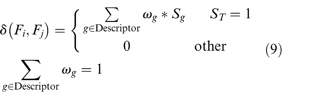
The similarity of the two machining features Fi and Fj denoted as δ(Fi, Fj) is then calculated as the weighted sum of the similarities of machining semantics, topology, and geometry. A heuristic rule about the weight setting is that the weight of the high-level information like machining semantics is larger than the weight of the low-level information like geometric shape
NC machining process reuse
Given a query feature, the feature similarity assessment approach merging with machining semantics will return the similar features to the user according to δ. By analyzing the similar features in the process of NC machining process reuse, two NC machining process reuse modes, that is, direct reuse and revised reuse, are defined. More in detail, the two reuse modes are described as follows.
Direct reuse
Direct reuse is suitable for the case that the similarity between the query feature and the similar feature is quite high. If δ is greater than a given threshold δ+, the NC machining process of the similar feature has high reuse value for the query feature. Thus, the machining operations associated with the similar feature, which has the highest similarity in the machining know-how database, can be selected as that of the query feature on the new part. In other words, the NC machining process of the similar feature can be reused by the query feature on the new part with only some parameterized adjustments implemented by the algorithm in Figure 6.
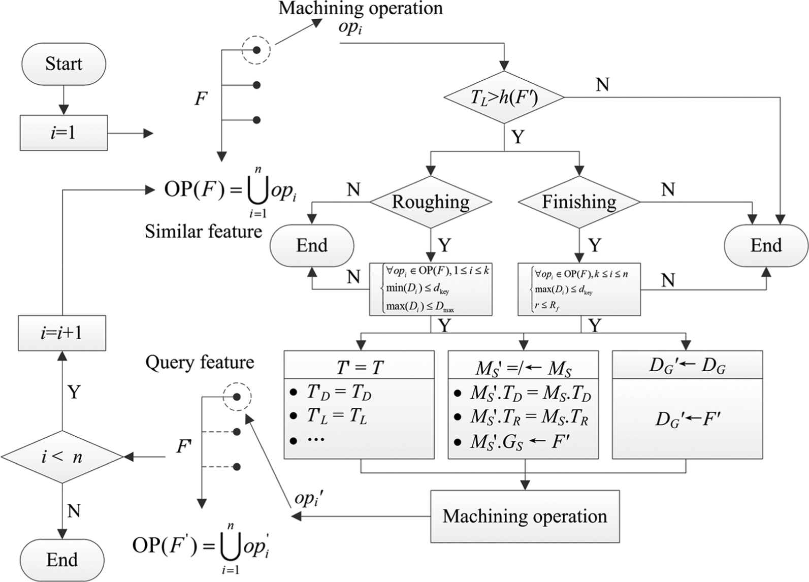
Process parameters reuse algorithm for similar feature.
Suppose that the NC machining process of a similar feature F is OP(F) and the component machining operation is opi, then OP(F) can be denoted as
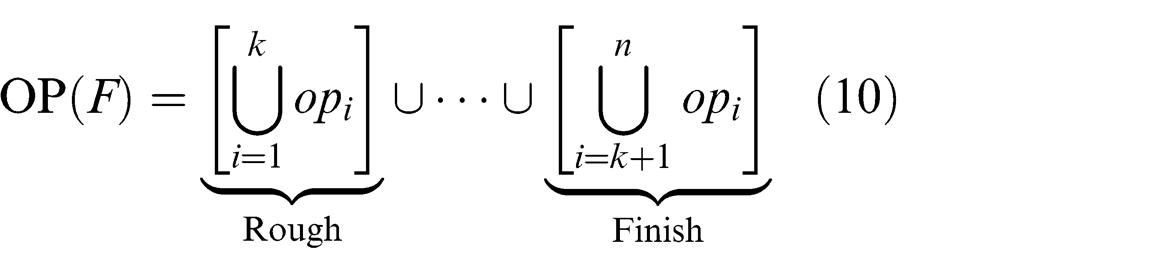
As shown in the above formula, there could exist multiple roughing operations (e.g. roughing and re-roughing) and finishing operations (e.g. bottom finish machining, side finish machining, and corner/fillet finish machining) associated with F. Next, the details of the process parameters reuse approach are explained.
Cutting tool
Before generating a machining operation, the cutting tool applied on the machining operation should be setup first. To reuse a cutting tool, the following parameters of the cutting tool must be compatible with the query feature F′.
Cutting tool length
To avoid the interference between the tool and the part, the cutting tool length (TL) is checked for the compatibility with the depth (h) of F′, if the following condition is satisfied
The length of the cutting tool is compatible with the depth of F′.
Cutting tool diameter
Similarly, the cutting tool diameter should also be checked for the compatibility with the widths of F′. Suppose that the minimum channel width of F′ is Dgap, the diameter of the maximum inscribed circle of F′ is Dmax, the minimum of the cutting tool radiuses for machining the corners of F′ is Rcmin, and the minimum of the cutting tool diameters for machining the sharp corners of F′ is ϕerr, then the key cutting tool diameter is denoted as
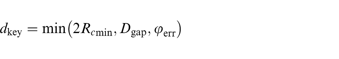
Here, Dgap, Dmax, Rcmin, and ϕerr are calculated in terms of the machining allowance requirements (e.g. corner machining allowance, side machining allowance) in each machining stage.
In roughing, the minimum diameter of the cutting tool should be less than or equal to dkey, and the maximum diameter of the cutting tool should be not greater than Dmax, that is
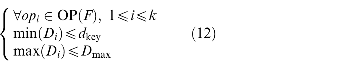
where Di is the diameter of the cutting tool applied on machining operation opi.
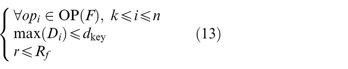
In finishing, the maximum diameter of the cutting tool is not greater than dkey, and the fillet radius (r) of the cutting tool should be less than or equal to the fillet radius (Rf) of F′, that is
When the cutting tool parameters of a machining operation are all compatible with F′, the parameters of the cutting tool can be directly reused without revision; otherwise, the associated NC machining process cannot be reused.
Machining strategy
In general, the parameters of machining strategy to be reused include the following: cutting mode (e.g. parallel, radiation, and spiral), approach/retract mode, cutting direction (downward/upward), machining tolerance, and cutting parameters (e.g. cutting speed vc, feed rate f, axial depth of cut ap, and radial depth of cut ae). It can be concluded from Mawussi and Tapie 17 that part of the parameters are related to the spatial position (GS) of machining geometries, for example, safe plane, cutter axis; part of the parameters are related to the topological relations (TR) of machining geometries, for example, cutting mode, approach/retract mode; and the other parameters are related to the technological data (TD) of the feature, for example, machining tolerance, cutting parameters.
Since the topological relations and the technological data are used in the feature similarity assessment as described above, it indicates that F′ has similar topological structure and technological data with F. Therefore, the machining strategy parameters related to the topological relations and the technological data are directly reused without revision, that is,
Drive geometry
It can be appreciated that tool path generation is driven by the process parameters and drive geometries. Here, the drive geometries are created by machining geometries of the feature itself. Therefore, for an arbitrary machining operation, drive geometry reuse is not reusing the machining geometries of the similar feature, but using the machining geometries of the query feature, that is,
Once the parameters of a machining operation are acquired, the machining operation can be automatically generated by making use of the application program interfaces (APIs) supplied by the CAM systems. Therefore, it will avoid a lot of repetitive workload, for example, manually select and define the parameters of MS, T, and DG in CAM software.
Revised reuse
Revised reuse is suitable for the case that the similarity between the query feature and the similar feature is little high. If δ∈[δ−, δ+], where δ− is the lower limit of the given threshold, the NC machining process of the similar feature has reference reuse value for the query feature, and the user will be inspired by the similar feature. In the revised reuse case, the user can get the machining features with a certain similarity to the query feature. This will be very helpful for the freshman-users on NC machining process planning, and the users can constantly accumulate the knowledge and experiences of NC machining process planning. For the case that δ is lower than δ−, it means that no similar features existed in Dp (i.e. no reusable NC machining process cases).
Experiment results and discussion
In order to verify the feasibility and effectiveness of our approach presented in this article, a prototype system of NC machining process reuse for similar features on the platforms of Microsoft Visual Studio 2003 and CATIA V5 R16 component application architecture (CAA) has been developed.
Use cases of machining feature similarity assessment
Figure 7 shows two parts from an aviation industry, and both the material of the parts are AMS6414. The technological data of the slot F1 and F2 are illustrated in Figure 7(a) and (b). Figure 7(c)–(f) shows the D2 shape distributions and FAAGs of F1 and F2, respectively. As the figure illustrates, F1 and F2 have the same topological structure, but have quite different geometric shape. With equations (1)–(9), the feature descriptors will be acquired (Table 2). As shown in Table 2, the similarity between F1 and F2 is 91.47%, larger than δ+ (δ+ = 90%). Therefore, the NC machining process of F2 has high reuse value for F1, although the similarity of D2 shape is only 64.8%.
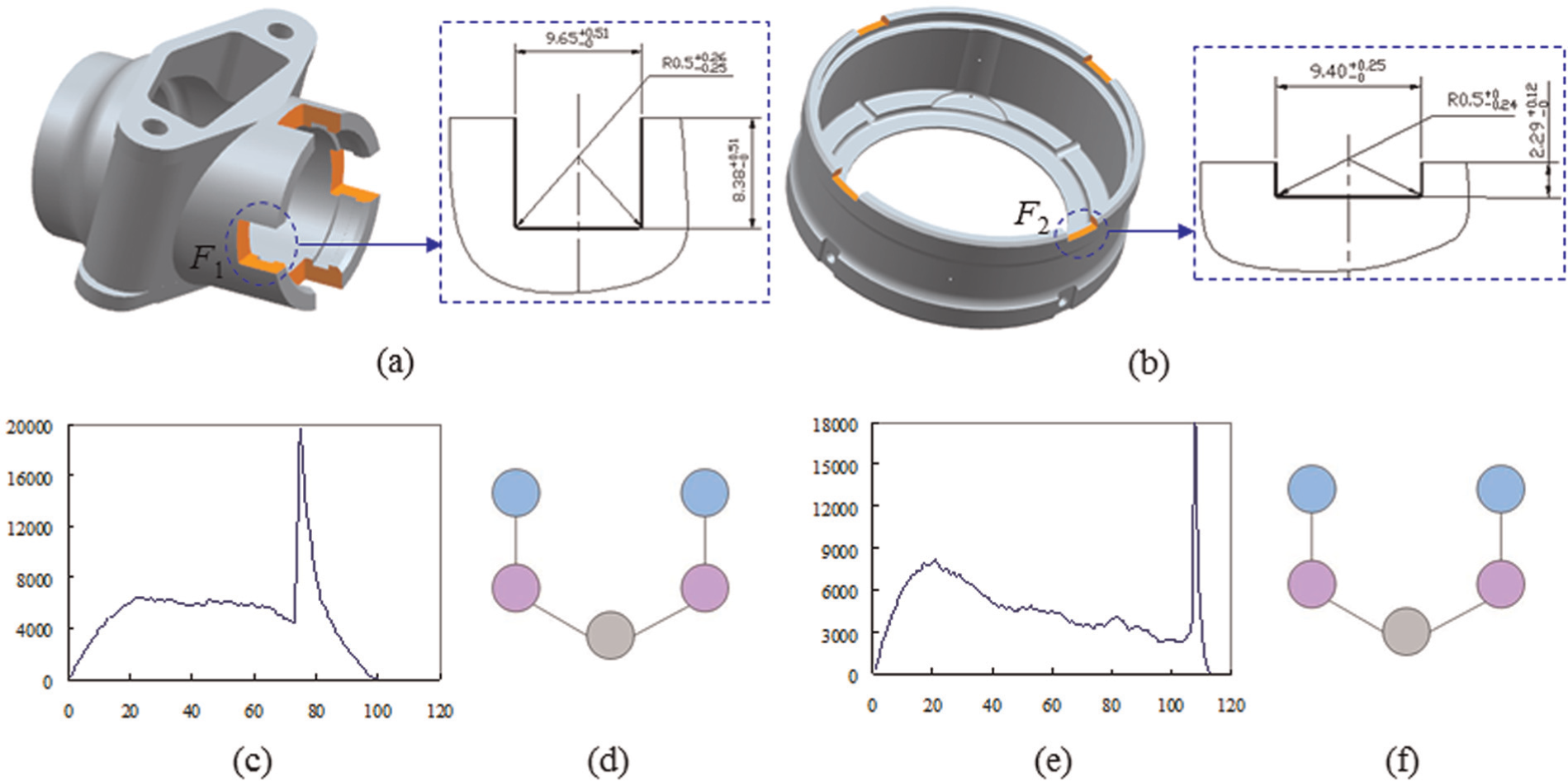
Two machining features from two different parts: (a) part 1, (b) part 2, (c) D2 shape distribution of F1, (d) FAAG of F1, (e) D2 shape distribution of F2, and (f) FAAG of F2.
Feature descriptors of F1 and F2.
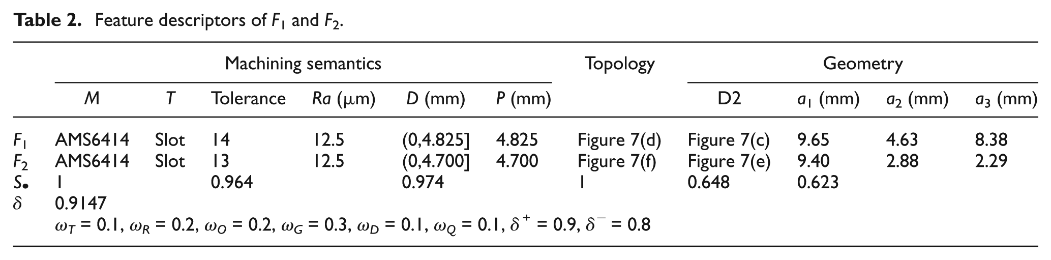
Figure 8 shows the retrieval results with F7 of the model Model_1 as query feature (here, only five models with the most similar features are given). The material of the five parts is 2A12-T4. The dimensional tolerance grade of F7, F8, and F9 is 9 and the surface roughness is 3.2, and they have the same FAAG. However, since F8 has higher similarity to F7 on openness and geometric shape, its similarity is higher than other machining features. As shown in Figure 8, only the similarity of Model_2 (95.79%) is larger than 90%. Therefore, F7 can reuse the NC machining process of F8 conditionally. Since the similarity between F9 and F7 is 85.58% (larger than 80%), the NC machining process of F9 has reference reuse value for F7 and has inspired significance.
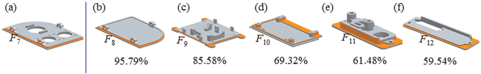
Retrieval results with machining feature F7 as query feature: (a) Model_1, (b) Model_2, (c) Model_3, (d) Model_4, (e) Model_5, and (f) Model_6.
The time complexity of the feature similarity assessment algorithm mainly focuses on the computation of maximal common sub-graph. Its time complexity is O(n2), where n is the number of the nodes of the association graph. The PC used for the experiments is a desktop with 1.80 GHz Inter(R) Pentium(R) Dual, 2.00 GB memory. The average run time of a model is 0.298 s, including feature descriptor extraction and comparison.
NC machining process reuse case
Figure 9 takes F1 and F2 as an example to illustrate the process parameters reuse approach, of which F1 and F2 are two pockets with islands. The NC machining process associated with F2 is shown in Figure 9(a), which contains three machining operations, that is, roughing, re-roughing, and finishing. Using the process parameters reuse algorithm described in Figure 6, the NC machining process for F1 can be generated automatically. Figure 9(a) shows the profile contouring operation of F2 for side finish machining with cutting tool D6, and the cutter axis is (0, 1, 0). The profile contouring operation of F1 for side finish machining will be generated automatically as shown in Figure 9(b) through reusing the parameters of MS, T, and DG. Here, the cutter axis, safe plane, and drive geometry should be revised in terms of the machining geometries of F1. For instance, the cutter axis is specified as (0, −1, 0), and the drive geometry is changed to the outer loop of the bottom face of F1. Moreover, the machining operation parameters are set automatically through using the APIs provided by CAM software (e.g. CATIA, UG) to avoid plenty of repetitive workload, which will improve the efficiency of machining operation planning.
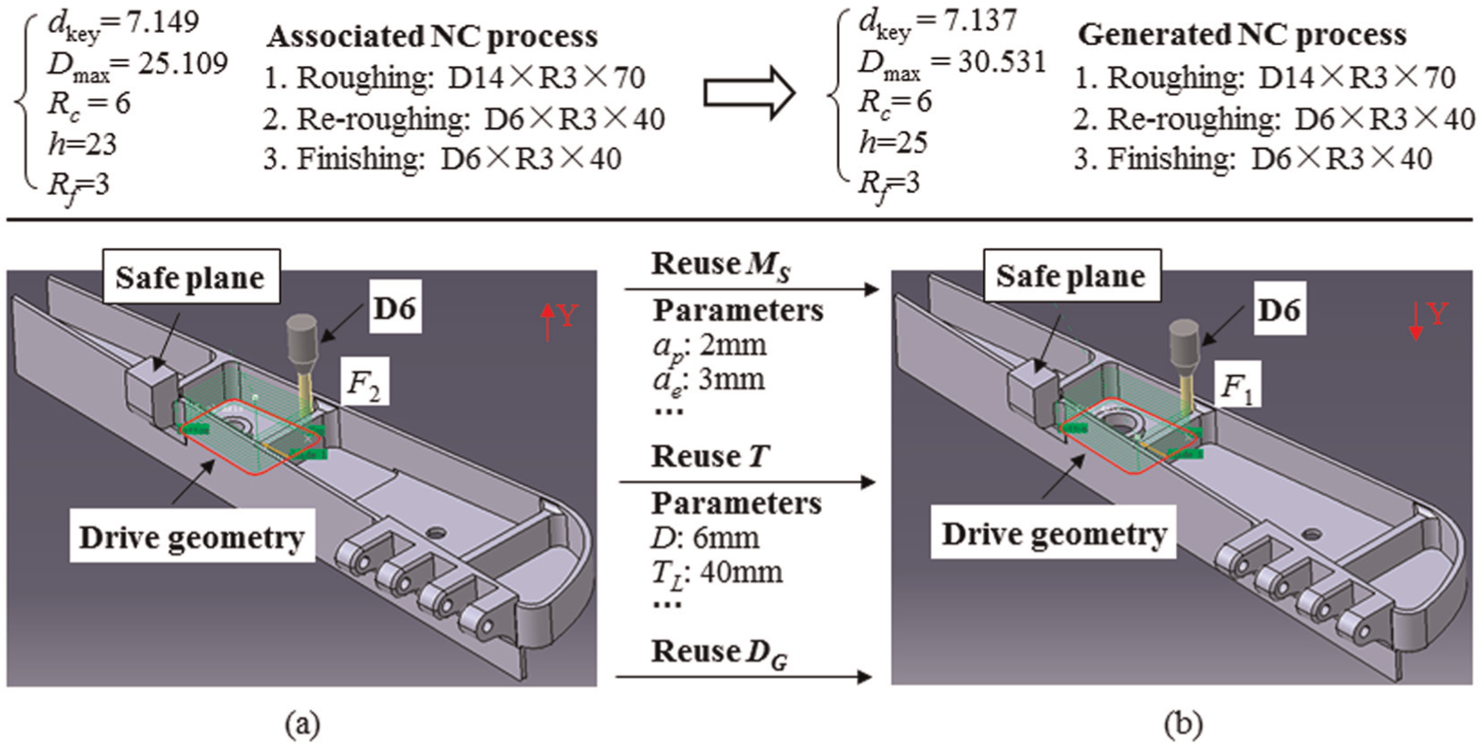
Example of NC machining process parameters reuse: (a) side finishing for F2 and (b) side finishing for F1.
Prototype system of NC machining process reuse
Figures 10–12 show the interfaces of the prototype system of NC machining process reuse for similar features. In this system, there are three main modules, that is, feature recognition and data mining for CAM models (Figure 10), feature similarity assessment (Figure 11), and NC machining process reuse implementation (Figure 12).
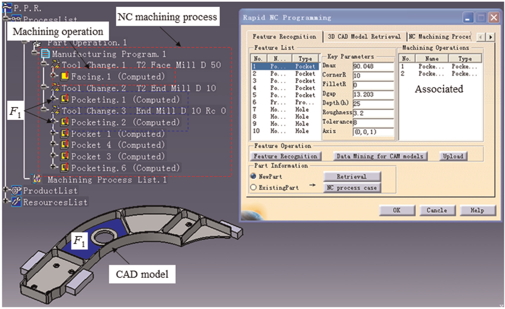
Feature recognition and data mining for CAM models.
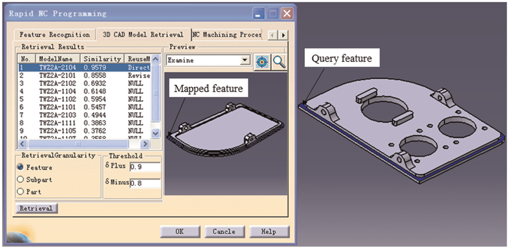
Machining feature similarity assessment.
NC machining process reuse.
The function of feature recognition module is to realize the seamless integration between CAD and CAM. The approach in Huang et al. 10 is used to recognize the machining features. In the process of feature recognition, the key parameters (i.e. Dmax, Dgap, and Rc) of the feature are computed correspondingly. For example, the Dmax of feature F1 is 90.048, and the Dgap is 13.203. With the recognized machining features of the CAM models in the repository, the machining know-how database is generated automatically using the data mining method described above. As shown in Figure 10, F1 is associated with two machining operations, and the associated machining operations are shown on the right of the module when the feature in the feature list is selected (see the left of the module). If the part is a new part, only feature recognition is carried out in this module.
The feature similarity assessment module illustrated in Figure 11 is designed for computing the similarity between features according to equation (9). The steps for this module are as follows: (1) select a query feature in the feature list in the feature recognition module (Figure 10), and (2) retrieve the similar features from the machining know-how database in the feature similarity assessment module. When a similar feature in the retrieval results (left of the module) is selected, the similar feature with the part will be shown in the preview dialog frame (right of the module), and the mapped feature will be colored. As shown in Figure 11, the first retrieval result is selected, and the color of the bottom face of the mapped feature is set to blue on the right of the module.
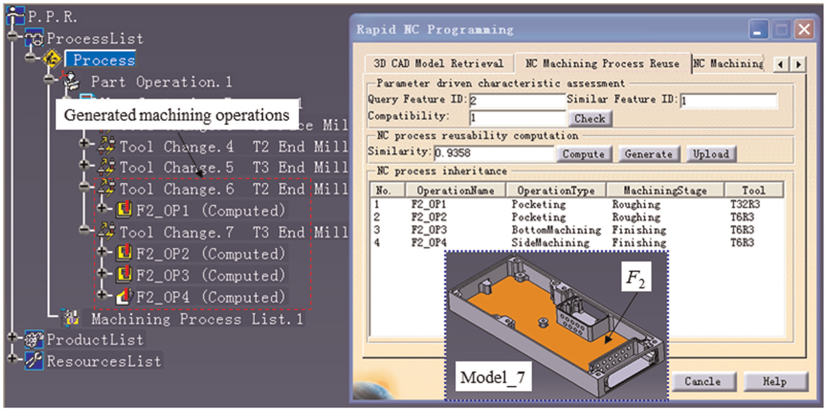
The function of NC machining process reuse is to generate the machining operations for the query feature automatically by reusing the process parameters of the selected similar feature. The interface of this module is demonstrated in Figure 12. The steps for this module are as follows: (1) specify a similar feature ID from the retrieval results in the feature similarity assessment module, and check the compatibility of the cutting tools with the query feature using equations (11)–(13); (2) generate the machining operations automatically. As shown in Figure 12, the similar feature ID is 1 (inherited from the retrieval results in the feature similarity module), and the query feature ID is 2 (inherited from the feature list in the feature recognition module). In addition, four machining operations are generated using the process parameters of the similar feature (left of the figure), of which the cutting tools of the four generated machining operations are T32R3 and T6R3, respectively. Here, the parameters of the automatically generated machining operations can be revised with the dialog of the CAM software itself as needed. Therefore, the prototype system developed is seamless integration with the CAM software, and it does not need to change the NC programming habit of engineers. According to the generated machining operations of the features, the NC machining process of the new part Model_7 can be generated by manually sequencing these machining operations.
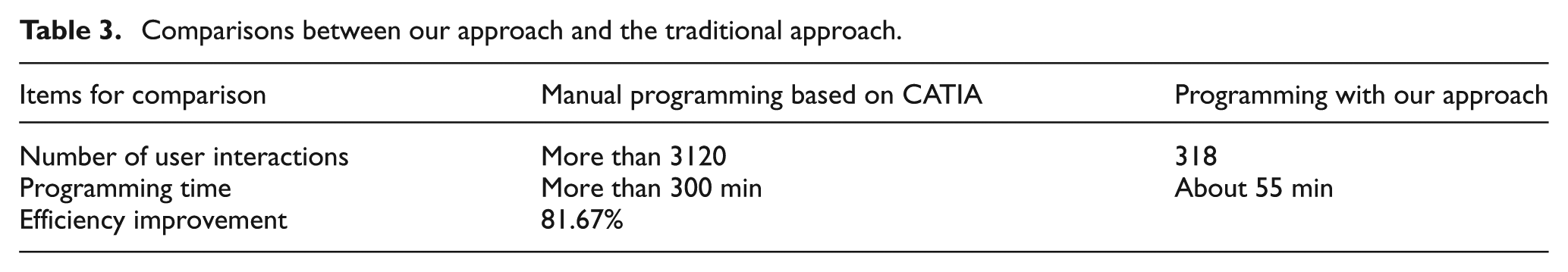
In order to demonstrate the significant improvement of our approach on efficiency, the comparisons with the traditional interactive programming based on CATIA system are listed in Table 3. It can be seen from the table that more than 3120 user interactions and 300 min are required to accomplish the NC programming for Model_7 through using the manual programming approach. However, with our approach, only 318 user interactions are required to complete the same task, and thus, the programming time is about 55 min. The NC programming efficiency is increased by 5 times evidently since lots of repetitive workload is avoided.
Comparisons between our approach and the traditional approach.
Conclusion and future work
In this article, a novel NC machining process reuse approach for similar features by merging feature similarity assessment and data mining for CAM models is presented. The experiments completed with our prototype system indicate that this approach can effectively and efficiently support NC machining process reuse to automatically generate the machining operations of the query feature.
Compared with traditional process reuse technology, such as group technology, our approach has the following characteristics and advantages:
The approach has considered more machining semantics for the feature similarity assessment, and some other machining semantics as needed can be more easily incorporated into the multilevel feature descriptor seamlessly as suitable properties than group technology.
The proposed feature descriptor is extracted from the machining feature automatically without human interactions, while the characteristics in the coding scheme are human interpretable which opens the door to error.
An accurate data mining for existing CAM models has been carried out to generate the machining know-how database automatically based on feature-based NC machining process model instead of manual collection.
Two NC process reuse modes are presented to automatically generate the NC machining process of query feature by reusing the associated machining operations of similar feature.
All these will allow the user to realize a more quantitative, finer, and rapid NC machining process reuse.
In the future, the generated machining know-how database will be optimized to make sure that the NC machining process of the same machining feature is optimized and then it will improve the NC machining process’ quality further. Another future work is to study the recombination and optimization between automatically generated machining operations of query features and manually generated machining operations of new machining features (no similar machining features existed in Dp) and expand the application domains of the proposed approach.
Footnotes
Declaration of conflicting interests
The authors declare that there is no conflict of interest.
Funding
This research was supported by the National Natural Science Foundation of P.R. China (nos 51375397, 51175434).