
Abstract
Welding distortion of pozidriv-type welded structure with rectangular pipes by 20 welding passes was examined with experimental and computational approaches, and mitigation techniques were also investigated for precision fabrication. Welding experiment to fabricate pozidriv type welded structure was conducted beforehand, and out-of-plane welding distortion was measured with contact type displacement sensor. Effective thermal elastic plastic finite element computation with iterative substructure method and parallel computation was developed, and then employed to examine the thermal-mechanical response during the entire welding process and predict the residual out-of-plane welding distortion. Good agreement between computed results and measurement data was observed with comparison. The influences of welding sequence and clamping constraint with tack welding on welding distortion were considered, which were also practiced for out-of-plane welding distortion mitigation. Both experiment and finite element computation show that out-of-plane welding distortion with welding sequence optimization and clamping constraint can be significantly reduced with about 38% and 56% magnitude of original welding distortion, respectively, while their mechanisms were also clarified by means of stiffness variation of solving welded structure.
Keywords
Introduction
In the fabrication of complex welded structure with multi-pass welding, welding induced distortion will strongly influence the dimensional accuracy and external appearance, as well as increase fabrication cost when straightening procedure is required and even change fabrication schedule and integral quality.1–3 For advanced precision fabrication, it is necessary to predict the possible welding distortion in advance before the actual fabrication, clarify the generation mechanism of different welding distortion and then validate the mitigation effect of proposed techniques.
With computational approach such as thermal elastic plastic (TEP) finite element (FE) computation, welding distortion can be predicted, and then is compared to measurement with good agreement.4,5 Computational welding mechanics has been widely used in welding industry to give designers the capability of residual stress and welding distortion prediction. However, massive requirements on computer memory and computing time make it less applicable to complex welded structures in actual engineering practice. Brown and Song6,7 employed both two- and three-dimensional FE models of a circular cylinder and a ring stiffened structure to investigate the effect of welding parameters such as weld gap, clearance, and fixture on welding distortion. Nishikawa et al. 8 developed the iterative substructure method (ISM) to reduce the computational time in three-dimensional welding analyses. In this method, the computational domain is divided into a large quasi-linear region and a small but moving strong non-linear region. Wang et al. 9 also concentrated on the behavior of arc welding, and developed ISM to consider welding problem as strongly non-linear region near welding arc and linear region away from welding arc. Later, a cylindrical leg structure of jack-up rig was examined for welding distortion prediction with ISM, and good agreement between computed results and measurement was observed. 10 Mondal et al. 11 examined the welding deformation in a submerged arc welded structure using equivalent load technique, while one-third computing time of conventional coupled transient, elasto-plastic, non-linear thermo-mechanical analysis can be reduced. The predicted welding distortions have good agreements compared with experimental as well as published results.
With high performance computer, Ikushima and Shibahara 12 developed a parallelized idealized explicit finite element method (FEM) using graphic processing unit (GPU) to examine the mechanical behavior of large-scale welded structures, in which dynamic explicit FEM is employed using shorter computing time and less memory. Ma 13 also proposed an accelerated explicit method and GPU parallel computing program to examine welding deformation of large welded structure with two steps: dynamic explicit method for thermal analysis and a static equilibrium computation for mechanical analysis. Parallel computation technique is also demonstrated to be an effective method to improve the computational speed. Kim et al. 14 developed a parallel multi-frontal solver for FE analysis of arc-welding process, in which phase evolution, heat transfer, and deformation of structures are considered. Tian et al. 15 performed a parallel calculation by establishing a computer cluster system composed of four personal computers (PCs) to predict the final distortion of a large complicated Al alloy structure during electron beam welding (EBW).
In order to reduce welding distortion and ensure fabrication accuracy, clamping constraint and welding sequence optimization are usually considered. Schenk et al.16,17 numerically studied the influence of clamping on welding distortion during the fillet welding, while the clamping condition strongly affects the welding distortion amplitude and might even alter the distortion mode. Liu and Zhang 18 also examined the influence of external restrains on welding angular distortion, and pointed out that angular distortion was almost the same with the same restraining moment no matter the location and magnitude of the restraining force. Gannon et al. 19 employed FE modeling to study the influence of welding sequences on the welding distortion when a flat-bar stiffener was welded to a steel plate. Chen et al. 20 considered welding sequence on welding distortion during the fabrication of a stiffened plate structure with longitudinal and transverse stiffeners.
From the literatures mentioned above, welding distortion prediction and mitigation were already examined. In this study, pozidriv type welded structure with rectangular pipes was considered during the lightweight vehicle fabrication, while large consumption of computing time with conventional computational approach was required and welding distortion during the actual fabrication is difficult to reduce without considering clamping constraint and welding sequence optimization. Welding experiment and measurement of out-of-plane welding distortion were carried out in advance, then according to the actual welding procedure, effective TEP FE computation based on ISM and parallel computation with open multi-processing (OpenMP) was proposed and employed for out-of-plane welding distortion prediction, while temperature-dependent material properties were considered. Good agreement between measured data and computed results can be observed not only for deformation tendency but also for magnitudes. Meanwhile, mitigation practices with clamping constraint and welding sequence optimization were numerically examined with proposed effective TEP FE computation. Both clamping constraint and optimized welding sequence can significantly reduce the out-of-plane welding distortion and ensure the fabrication accuracy, while stiffness variation was proposed for mechanism investigation.
Methods of effective TEP FE computation
Thermal-mechanical behavior during welding process is usually investigated with non-linear transient TEP FE computation, and some advanced techniques such as ISM and parallel computation with OpenMP, were proposed to enhance computational efficiency for complex welded structure in actual industry application.
Conventional TEP FE computation
For the welding process modeling with TEP FE computation, there are two physical behaviors, thermal process and mechanical process, and uncoupled thermal-mechanical formulation is usually considered. With the investigation on the thermal-mechanical response during welding process, transient temperature profile, welding residuals stress as well as welding distortion can be examined and predicted. Meanwhile, the contribution of transient temperature field to mechanical response was examined through linear thermal expansion, as well as temperature dependent thermal physical and mechanical properties.
In order to deal with the welding thermal-mechanical response and considering the non-linear feature of temperature-dependent material properties, computational procedure with two steps was proposed.21,22 The transient temperature profile is obtained by solving a partial differential equation of the conservation of energy as given by equation (1) during the heat transfer analysis beforehand, while the heat flux boundary is considered. Then, the obtained transient temperature distribution is applied as a thermal loading in the subsequent mechanical analysis to examine the residual stresses, plastic strains and welding distortion, while the material constitutive relation and Mises yield criteria are employed. In detail, a partial differential equation of the conservation of momentum as given by equation (2) will be numerically solved during the mechanical analysis
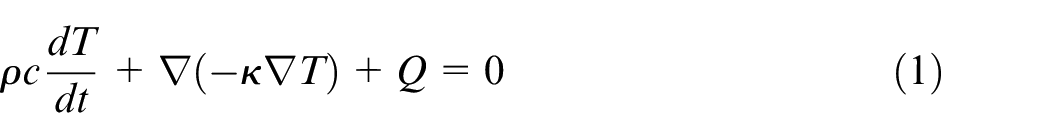
where T is the temperature and ▽T is the temperature gradient, Q is the power per unit volume or the power density distribution, k is the thermal conductivity, c is thermal capacity and ρ is density. These material properties are usually temperature dependent
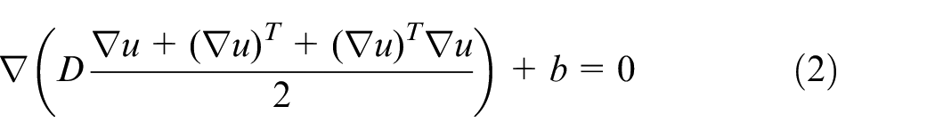
where D means the fourth order elastic-plastic tensor as a 6 × 6 matrix, b is the body force, and u is the displacement vector.
For the numerical analysis, some computational configurations should be assumed such as the following: initial temperature is fixed to be ambient temperature and body heat source with uniform heat flux density is employed to model welding arc. In order to improve the computational efficiency and precision, small time increment during welding time is used and exponential time increment will be applied after welding completion till cooling down to ambient temperature.
Iterative substructure method
From the view of physical behavior, a local high-intensity power source caused by welding arc with moving is applied to the steel plates during the welding process, and then generates a sharp thermal profile in the nearby region and results in non-uniform distribution of plastic strains as well as welding residual stress.
Mechanical response generated by welding process has a significant non-linear characteristic; however, this phenomenon obviously occurs in a narrow region near the welding arc. In the conventional TEP FE analysis, it is normal to consider the welding process as a non-linear problem in the whole considered region, and solve it for the entire process and total mesh domain. As mentioned, weakly non-linear even elastic FE analysis can be carried out for the region far away from the welding arc when the current temperature of point is not high enough, and the region with strongly non-linear analysis moves together with the welding heat source. Therefore, an ISM was developed as a whole computational domain is divided into a weakly non-linear region, a strongly non-linear region and fictitious boundary as shown in Figure 1, which will be updated with the moving welding heat source. 8 Meanwhile, the stiffness matrix of the weakly non-linear region is updated only when it is necessary to economize the computing time. Wang et al. 9 employed the TEP FE computation with ISM to predict the twisting welding deformation during the fabrication of stiffened welded structure, and good agreement between computed results and measurement was observed. The origin of strongly non-linear region is always identical to the moving welding arc, and which size is determined by either maximal temperature or distance to welding arc.
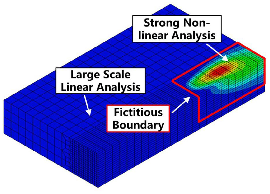
Illustration of iterative substructure method (ISM).
Parallel computation techniques
For the conventional TEP FE analysis, the program is constructed, and compiled by single thread mode with lots of time consumption. Thus, computation cannot utilize the advantage of multi-threads of high performance server to enhance the computational efficiency. Parallel computation with OpenMP technology was developed as a guided compilation processing scheme, which can be implemented for multi-threads central processing unit (CPU) with shared memory operation system. 23 Then, effective TEP FE computation, which was already accepted and employed for computational mechanics, can be achieved by means of utilizing multi-threads.
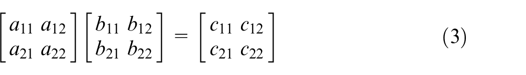
Based on the OpenMP technology with open source project, parallel computation is becoming much easier for researcher and scientist, and the program can be compatible and supported with lots of computer language, such as C, C ++, or FORTRAN. Taking two ranked matrices multiplication given in equation (3) as an example, parallel computation will transfer two ranked matrix to four vectors, and then four vector multiplication operations are carried out simultaneously with different thread as demonstrated in equation (4)
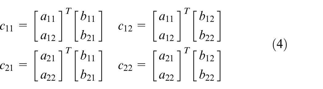
For the computational welding mechanics, the reading and writing process are normally completing with single thread mode, and operation of large range matrix is solved by OpenMP technology with multi-threads mode. 13 In detail, temperature stiffness matrix during thermal analysis and mechanical stiffness matrix during mechanical analysis will be divided into sub-matrices, and arranged for different thread for parallel computation. Thus, much more threads were employed for one computation, and computing time can be significantly reduced. The in-house code was programmed by FORTRAN, and then compiled with Intel Parallel Studio XE 2011 based on the platform of Ubuntu 14.04 OS and Dell PowerEdge T420 Server.
Welding procedure and measurement
Pozidriv type welded structure as a special case was examined and fabricated experimentally. In detail, considered pozidriv type welded structure is consisted of rectangular pipes. Their geometrical feature and number are summarized in Table 1, and the material is low carbon steel Q235 (yield stress about 235MPa).
Rectangular pipes information of pozidriv type welded structure.
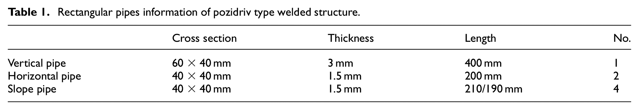
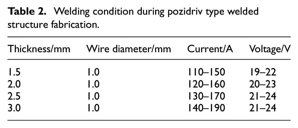
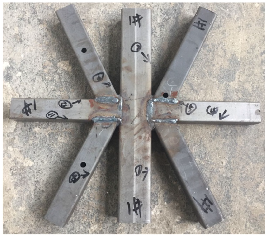
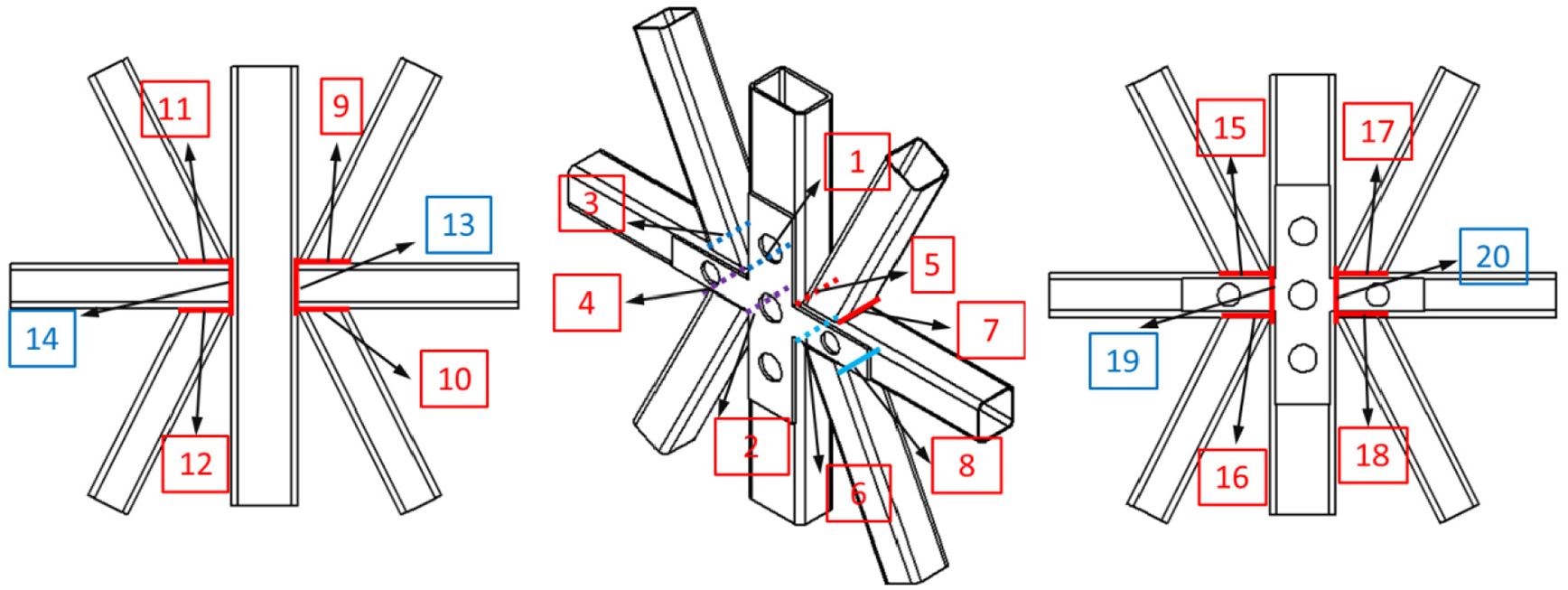
According to the design, the shape of examined pozidriv type welded structure is shown in Figure 2, in which one vertical pipe is considered as the base, two horizontal pipes are welded to vertical pipe with 90° angle, and four slope pipes are then welded to horizontal pipes with a certain angle. Figure 2(a) also shows the dimensional size and location of each rectangular pipe with the front view. Meanwhile, the purpose of cross workpiece as shown in Figure 2 is to confirm the positions of all rectangular pipes, which will be removed after tack welding and will not appear during the actual welding process. Table 2 lists the welding condition for rectangular pipes welding due to the different thickness, and the current welding sequence with 20 welding passes during fabrication is illustrated in Figure 3.
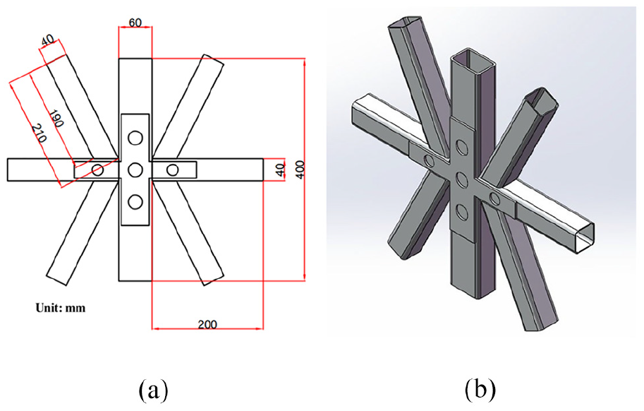
Image of pozidriv type welded structure: (a) Dimensional size and front view. (b) Overall image.
Welding condition during pozidriv type welded structure fabrication.
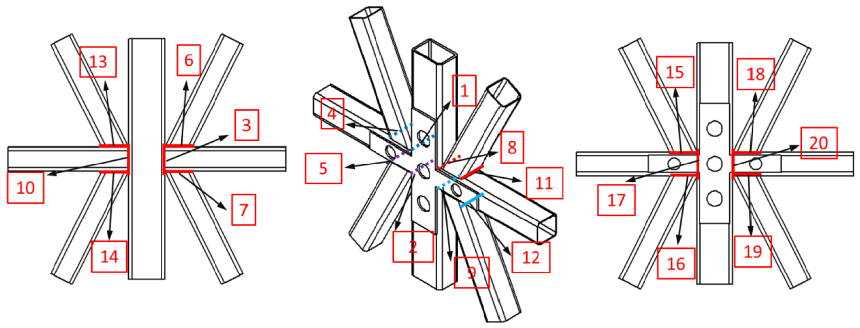
Welding sequence during pozidriv type welded structure fabrication.
At the beginning of welding procedure, tack welding was at first applied to fix all rectangular pipes as the design shape as shown in Figure 4. In Figure 5, welding sequence was also marked on the specimen for the welder to follow. With the practical testing of welding technique with gas metal arc welding (GMAW), the flux-cored wire with 1 mm diameter was applied, and welding current and voltage are fixed as about 140A and 21 V, respectively. Due to the size of rectangular pipes, the length of welding seam is 40 mm and welding time is about 5–6 sec.
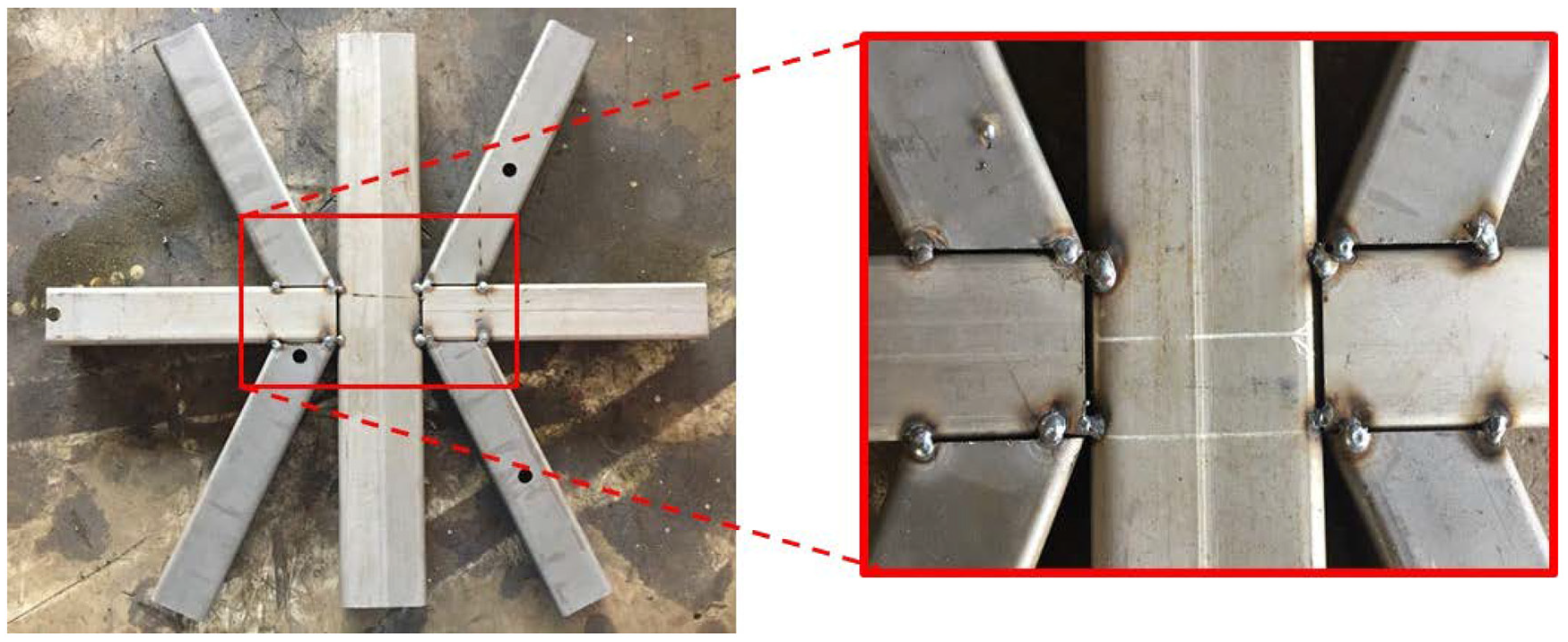
Pozidriv type welded structure with tack welding.
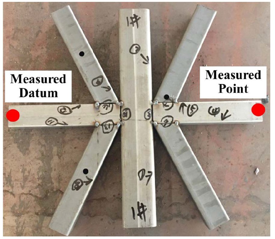
Welding sequence and measured point mark on specimen.
After all welding completion and cooling down, out-of-plane welding distortion was measured by means of contact type displacement sensor, which actually is a three-wire displacement varistor and can work under temperature from −35°C to 80°C. Measured range and precision are 20 mm and 0.003 mm, respectively. In addition, the magnitudes of out-of-plane welding distortion of horizontal pipe, which are considered as the maximal out-of-plane welding distortion of overall pozidriv type welded structure as also indicated in Figure 5, are about 5 mm after front welding and about 1.5 mm after back welding as shown in Figure 6. Figure 7 shows the final shape of pozidriv type welded structure with 20 welding passes.
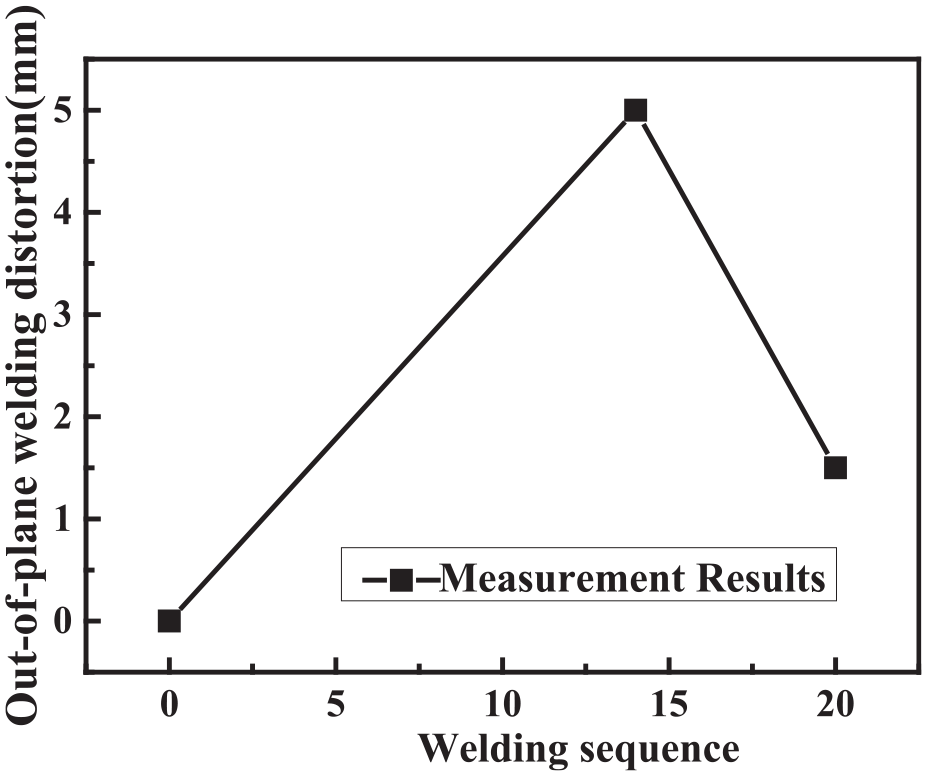
Measurement of maximal out-of-plane welding distortion (horizontal pipe) during welding sequence.
Pozidriv type welded structure after welding.
Welding distortion prediction with effective TEP FE computation
In order to investigate the mechanical behavior as well as welding distortion prediction of complex welding structure, not only the ISM but also parallel computational technology with OpenMP were employed to enhance the efficiency of conventional TEP FE computation, and an in-house code was developed and implemented in the Dell T420 server with 40 threads.
Based on the geometrical characteristic of examined pozidriv type welded structure and considering the welding procedure, solid brick elements with 8 nodes were employed to make a FE model by commercial software (MSC Patran) as shown in Figure 8, while 20 weld passes were marked with the different color. The number of nodes and elements are 47,318 and 34,192, respectively. Meanwhile, the IsoMesh and MeshTransition techniques were used for generating the fine mesh near welding region, relatively coarse mesh away from welding line and smooth mesh transition between them, which will be effective to ensure computational accuracy and reduce huge consumption of computer resource.
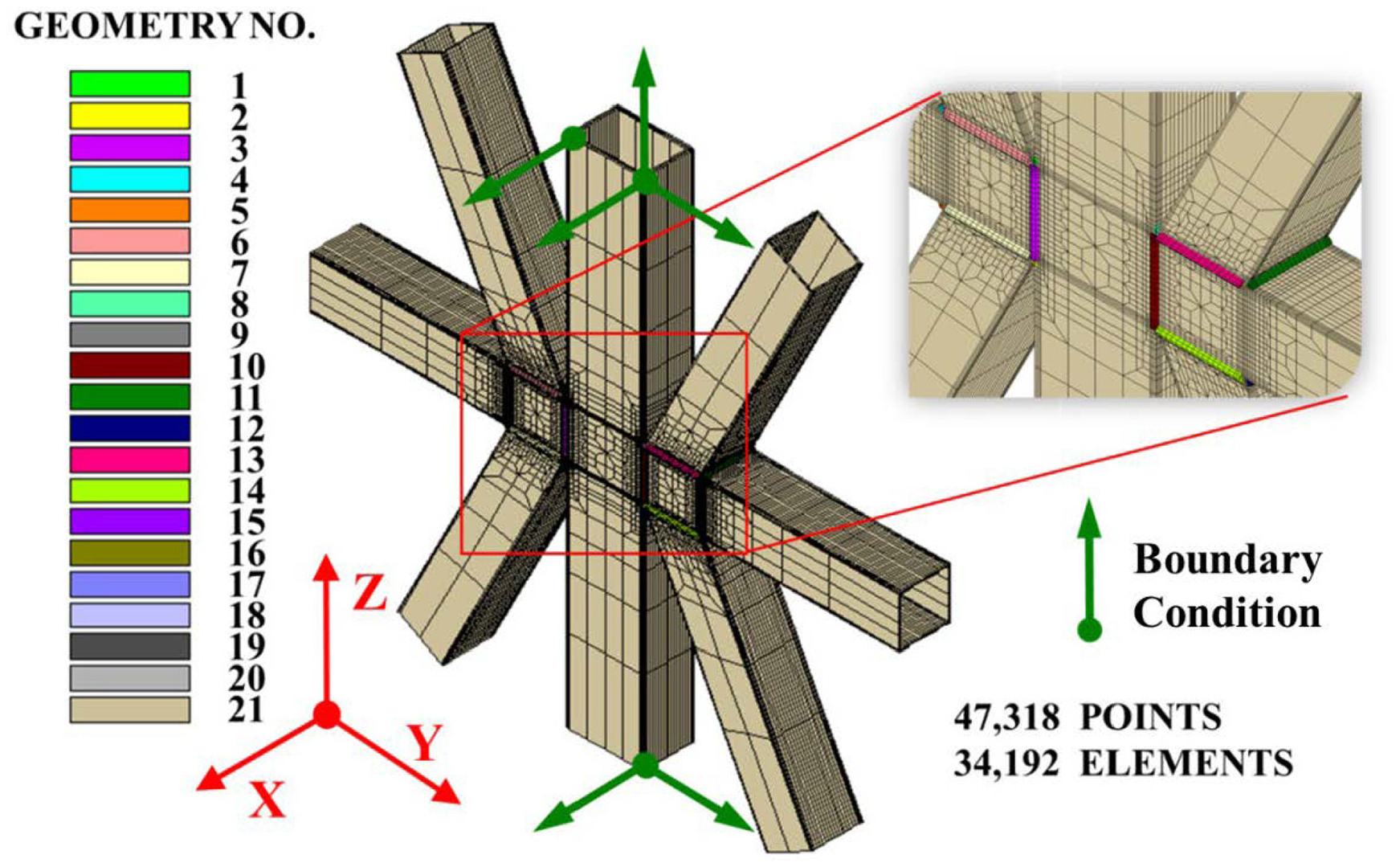
Solid brick elements model of pozidriv type welded structure.
For investigating the welding process, initial temperature is assumed to be ambient temperature during thermal analysis. Since body heat source has good computational precision for considering transient feature of welding temperature field, body heat source with uniform power density (w/m3: welding arc energy/volume of body heat source) is usually employed to model thermal profile of welding arc. Magnitude of body heat source is determined by heat input as well as the welding condition as defined in equation (5), and heat losses due to convection and radiation are also taken into account as heat flux boundary condition for all external surfaces. 21 Heated elements are determined by origin of welding arc, width, height, depth and length of welding heat source. In addition, non-linear temperature-dependent material properties as shown in Figure 9 were applied, which have significant influence on the computed results during both thermal analysis and mechanical analysis
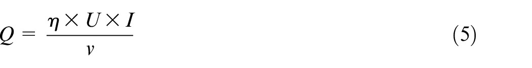
where η means thermal efficiency of welding arc, U and I are welding voltage and welding current, respectively, and v means welding velocity.
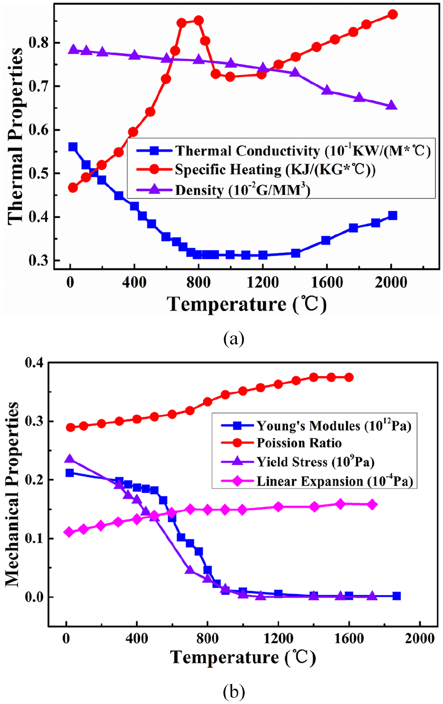
Temperature-dependent material properties of Q235: (a) Thermal properties.(b) Mechanical properties.
With thermal analysis mentioned above and corresponding computation, transient temperature distributions during vertical and flat position welding were demonstrated in Figure 10. It can be seen that temperature gradient has an obvious difference in the regions of front and rear of welding arc, which is consistent to the actual physical behavior due to temperature gradient along the moving direction of welding arc. Figure 11 gives the plotting contour of maximal temperature during entire welding process, as well as the geometrical characteristics of 20 weld pools according to the design.
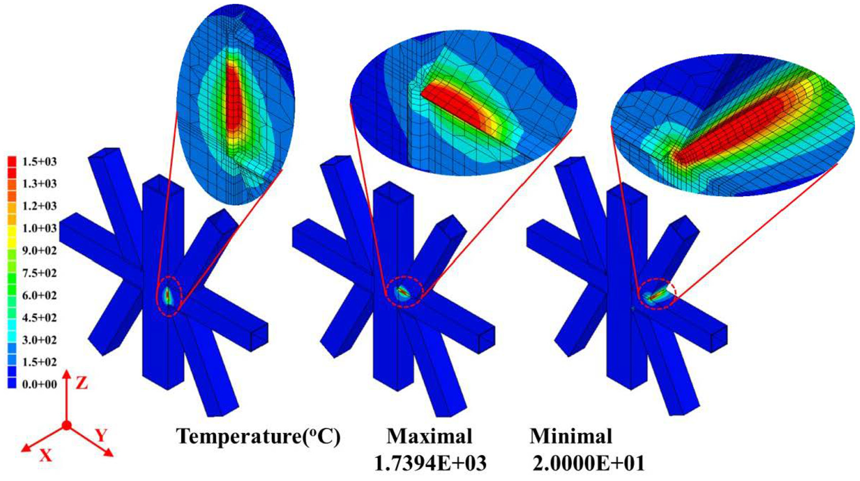
Transient temperature distribution of computed results.
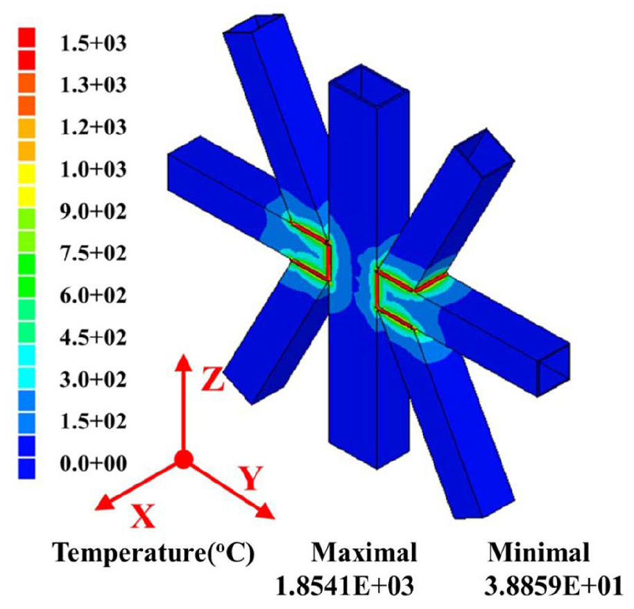
Plotting contour of maximal temperature during entire welding process (weld pool).
Applying computed temperature profile as thermal loading and considering non-linear temperature-dependent mechanical properties as shown in Figure 9(b), mechanical analysis during welding was carried out by means of elastic-plastic responding investigation. In addition, initial stress is always assumed to be stress free and rigid body motion is usually prevented with nodes constraint as shown in Figure 8 to be boundary condition for welding distortion prediction during mechanical analysis. Figure 12 shows the computed out-of-plane welding distortion in X direction after 20 welding passes. It can be found that the maximal out-of-plane welding distortion occurs at the edges of horizontal rectangular pipes. Therefore, point 1 and point 2 as indicated in Figure 13 are selected to examine the transient out-of-plane welding distortion after each welding pass for comparison with measurement data. Figure 14 demonstrated the tendency of out-of-plane welding distortions of points 1 and 2 after each welding pass, and good agreement between computed results and measurement can be observed. Meanwhile, computed out-of-plane welding distortions of point 1 and point 2 are the displacement with respect to boundary condition during mechanical analysis. Therefore, computed welding distortion as shown in Figure 14 means the total magnitude of out-of-plane welding distortions of point 1 and point 2, while point 1 was considered as measured datum compared to experimental measurement. It also can be seen that the magnitude of computed out-of-plane welding distortion continuously increases with front view welding, and decreases during back view welding due to opposite mitigation.
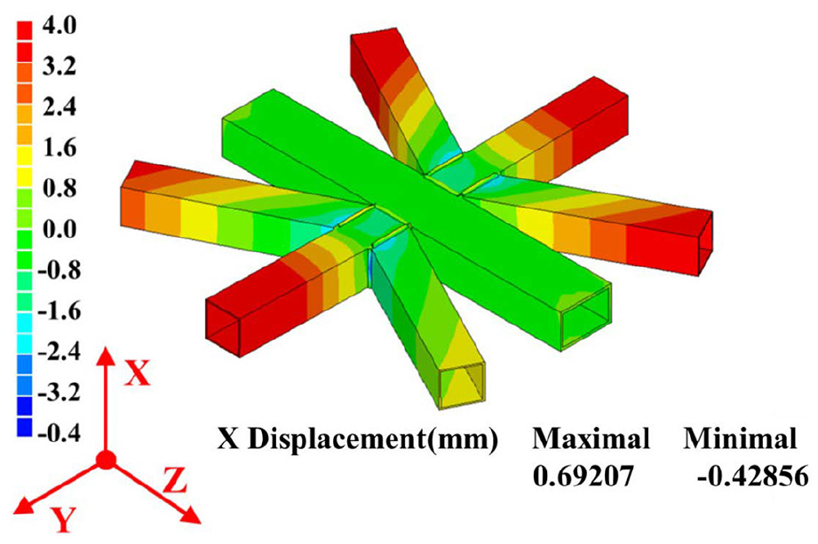
Predicted out-of-plane welding distortion (deformed rate: 5).
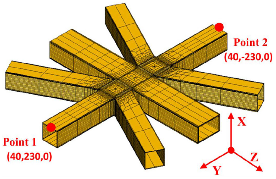
Locations of examined points for welding distortion comparison.
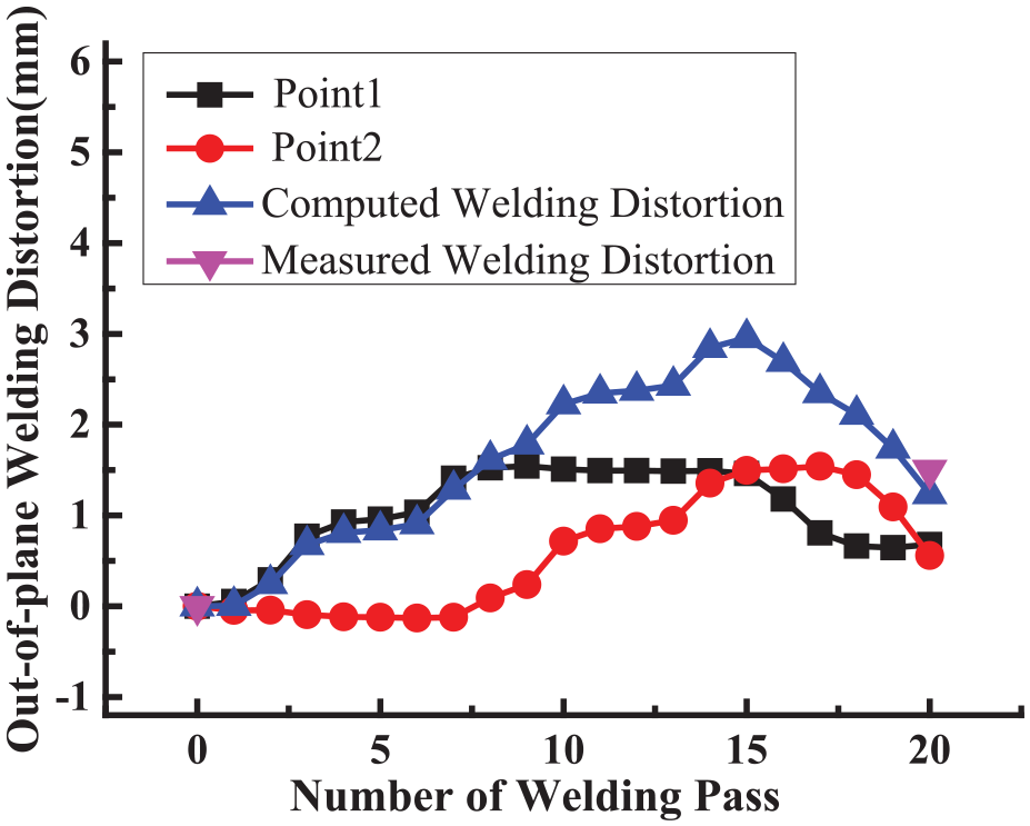
Comparison of out-of-plane welding distortion.
Advanced technique for welding distortion reduction
In order to reduce the welding distortion and improve the fabricated precision, some advanced techniques, such as welding sequence optimization and clamping constraint, are usually employed, and examined for welding distortion control during academic research and actual fabrication.
Influence of welding sequence
Due to the lots of rectangular pipes as component with 20 welding passes for pozidriv type welded structure fabrication, the welding sequence will influence the structural rigidity and then out-of-plane welding distortion. In mechanical mechanism, the welding sequence will reduce the welding distortion and ensure the final fabrication precision due to influencing the whole stiffness of considered welded structure.
As mentioned above, the out-of-plane welding distortions are 2.96 mm after front welding and 1.24 mm after back welding with the welding sequence as shown in Figure 3.
Generally, when the welding heat input and external fixture are identical, variation of structural stiffness will obviously influence the welding distortion and final dimension. Optimization of welding sequence to rapidly improve the stiffness of considered welded structure is an efficient approach to reduce welding-induced distortion. There are two options of welding sequence: (1) Horizontal and slope pipes are all assembled with vertical position welding to vertical pipe beforehand, and then horizontal pipe is welded with slope pipes by flat position welding. (2) Half section, including one horizontal pipe and two slope pipes, is assembled completely in advance and then welded with vertical pipe. Based on the fabrication experience as well as rigidity prior principle with theoretical analysis, the large component or piece should be assembled and welded as earlier as possible, which can efficiently resist bending deformation caused by welding due to structural stiffness reinforcement.
With first optimized welding sequence as shown in Figure 15, Figure 16 shows the evolution of out-of-plane welding distortion of point 1 and 2 as indicated in Figure 13, which were also compared to that with experimental welding sequence. It can be seen that final welding distortion almost has the same magnitude; however, the evolution tendency has obvious difference due to different welding sequence.
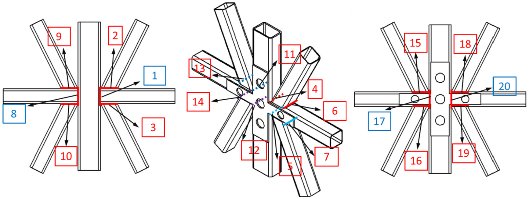
First optimized welding sequence with vertical position welding beforehand.
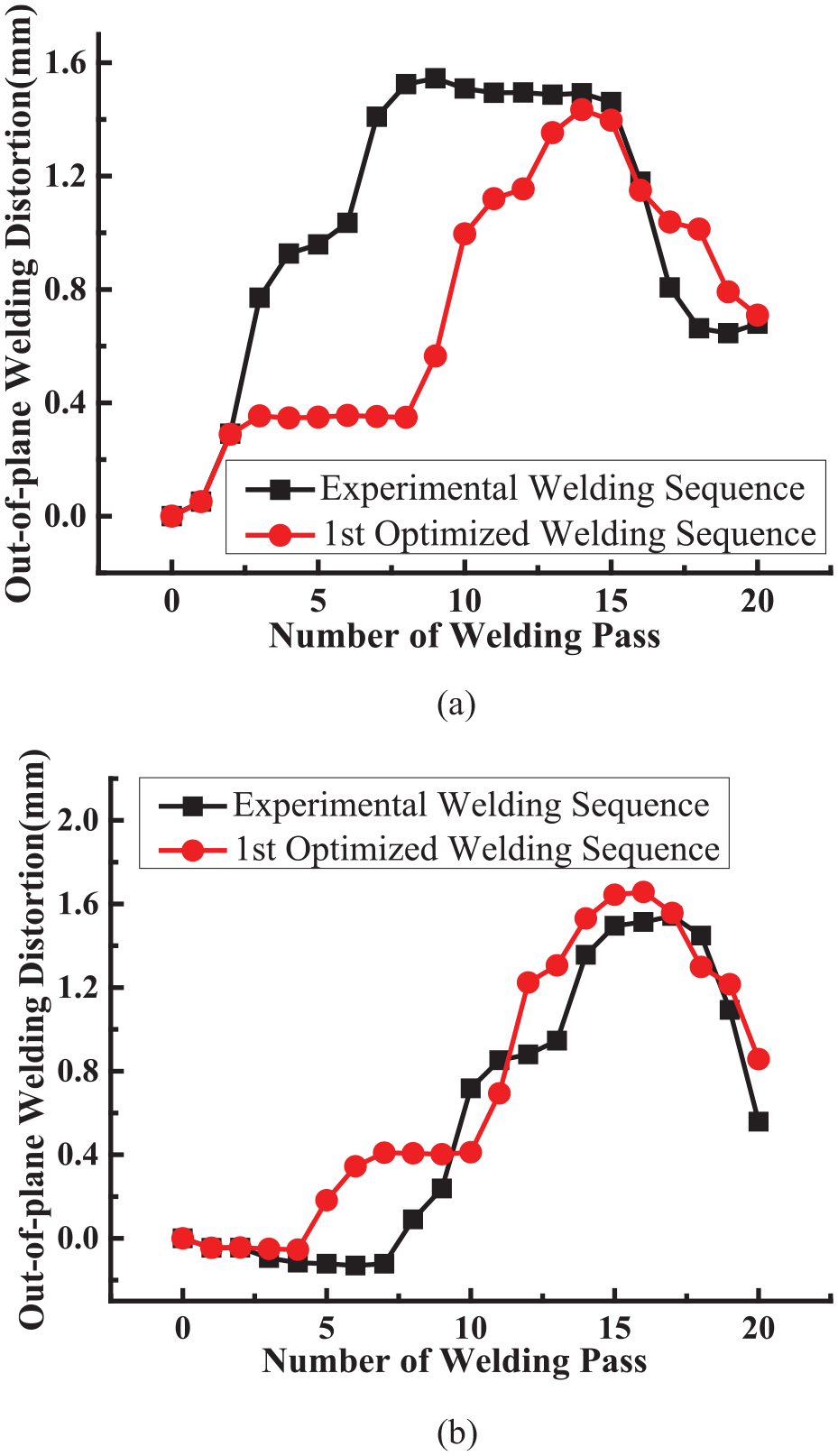
Comparison of out-of-plane welding distortion between experimental and first optimized welding sequences. (a) Evolution of out-of-plane welding distortion of point 1. (b) Evolution of out-of-plane welding distortion of point 2.
Meanwhile, out-of-plane welding distortion with second optimized welding sequence as shown in Figure 17 has a significant reduction. Evolutions of out-of-plane welding distortions of points 1 and 2 as shown in Figure 13 are illustrated in Figure 18, and also compared to that with experimental welding sequence. Furthermore, overall out-of-plane welding distortions are computed and compared as shown in Figure 19, in which absolute magnitude of out-of-plane welding distortion is reduced from 1.24 mm to 0.77 mm by 38%.
Second optimized welding sequence with half section fabrication beforehand.
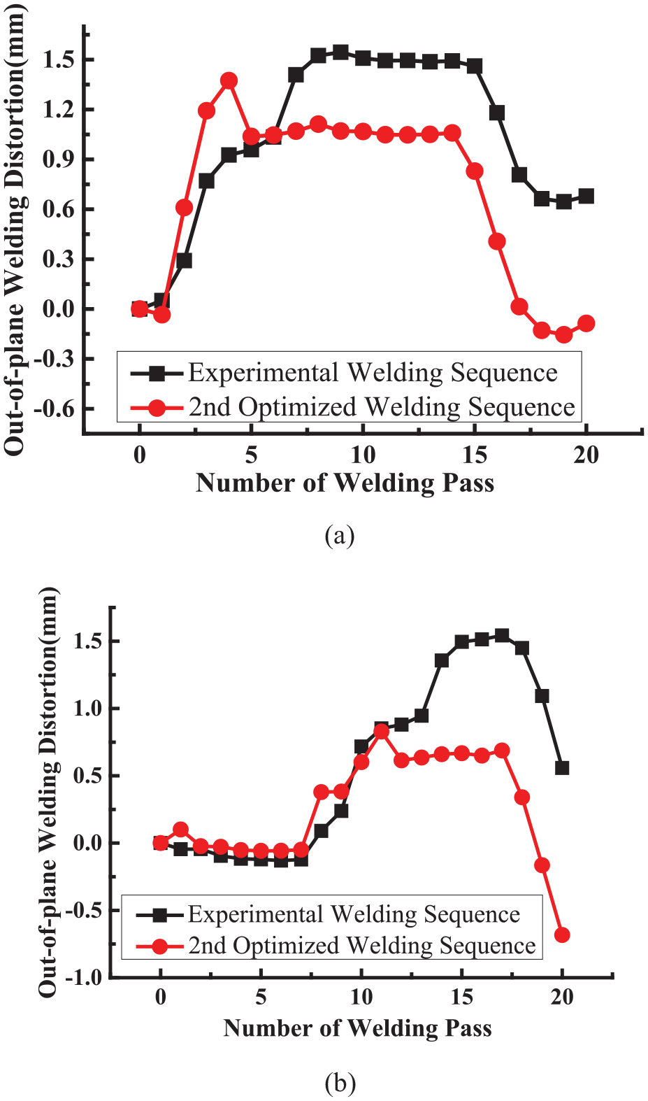
Comparison of out-of-plane welding distortion between experimental and second optimized welding sequences. (a) Evolution of out-of-plane welding distortion of point 1. (b) Evolution of out-of-plane welding distortion of point 2.
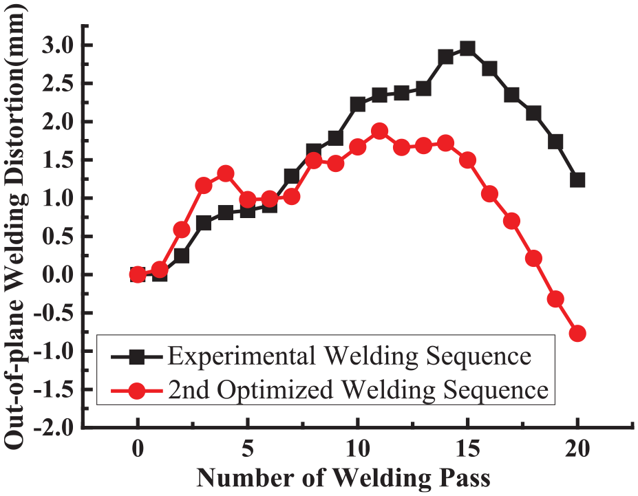
Comparison of overall out-of-plane welding distortions between experimental and second optimized welding sequences.
The generation mechanism for out-of-plane welding distortion mitigation with different welding sequence can be clarified by means of variation of structural stiffness. When the welded components with large structural stiffness were assembled together in advance, the subsequent out-of-plane welding distortion generated by welding process will be less due to the same welding condition (driving force) and large structural stiffness (rigidity resistance). Therefore, rigidity prior method (RPM) is usually considered for welding sequence optimization with less out-of-plane welding distortion during the fabrication of complex welded structures.
Influence of clamping constraint
In actual fabrication, fixture constraint is usually employed to control out-of-plane welding distortion. Thus, pozidriv type welded structure was initially fixed together with tack welding, and then two horizontal rectangle pipes were tack welded to the platform with rigid clamping beforehand as shown in Figure 20. After the completion of front welding with 14 welding passes, tack welding with platform was removed and then pozidriv type welded structure was turned over for back welding with other 6 welding passes. With the transient welding distortion measurement during the assembly procedure, the magnitudes of out-of-plane welding distortion are 2 mm after the completion of front welding and −1.5 mm after completion of back welding.
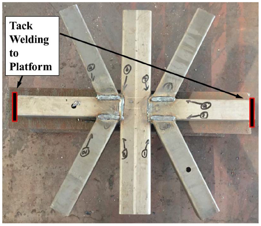
Tack welding to platform for clamping of pozidriv type welded structure.
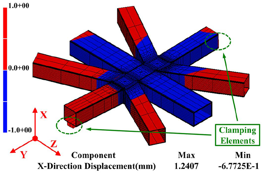
With computational analysis under the effect of clamping constraint by non-linear clamping elements, plotting contour of predicted out-of-plane welding distortion after 14 front welding passes is demonstrated in Figure 21 considering the clamping constraint of tack welding to platform. Meanwhile, Figure 22 illustrates the dimensional changing of pozidriv type welded structure after clamping release due to the springback behavior of clamping elements. It can be seen that clamping release will generate additional dimensional tolerance due to springback with the clamping elements; however, clamping with tack welding can efficiently reduce the out-of-plane welding distortion in general.
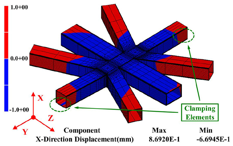
Plotting contour of out-of-plane welding distortion under clamping with tack welding (after 14 front welding passes).
Plotting contour of out-of-plane welding distortion after clamping release (after 14 front welding passes).
Furthermore, Figure 23 shows the evolution and comparison of out-of-plane welding distortions with and without clamping constraint by computational analysis. It can be found obviously that clamping with tack welding can significantly influence the evolution of out-of-plane welding distortions. In addition, out-of-plane welding distortion generated by six back welding passes without clamping constraint not only offsets the previous welding distortion but also reverses the pozidriv type welded structure to the opposite direction eventually. Also, clamping constraint reduced the magnitude of overall out-of-plane welding distortion from 2.96 mm to 1.18 mm by 60% at the moment of clamping release, and while absolute magnitude of overall out-of-plane welding distortion after assembly completion is reduced from 1.24 mm to 0.55 mm by 56%.
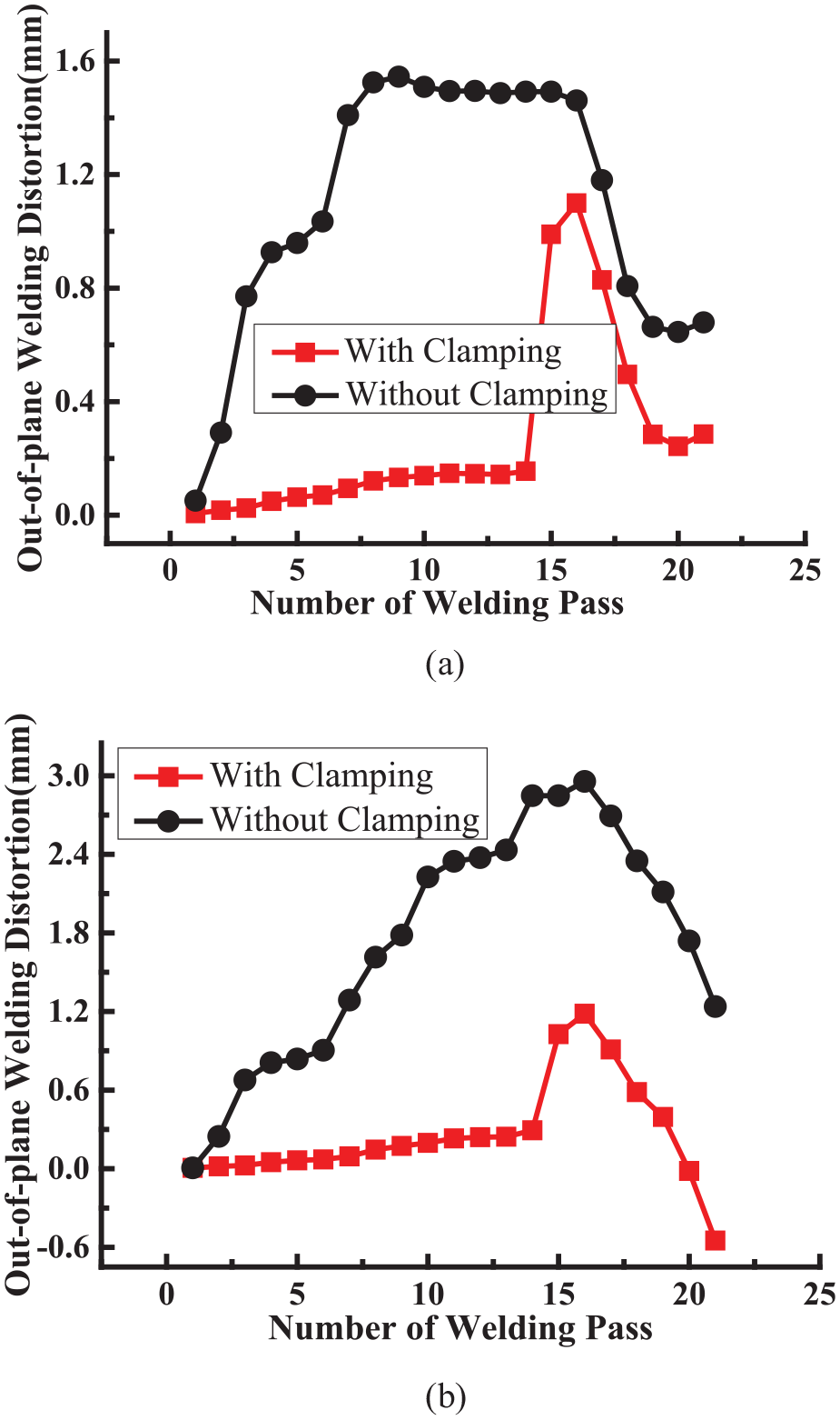
Comparison of computed out-of-plane welding distortions with clamping and without clamping. (a) Evolution of out-of-plane welding distortion of point 1.(b) Evolution of overall out-of-plane welding distortion.
In order to examine the behavior and influence of clamping constraint, non-linear element, the so-called clamping element, was presented to consider the springback response after clamping release. In addition, the stiffness of clamping element is assumed to be strong enough (1010 Pa) during welding process for out-of-plane welding distortion constraint, and after clamping release, the stiffness of clamping element is switched to be weak (10−2 Pa) for investigation of springback response. Not only behavior of clamping influence but also tendency of out-of-plane welding distortion has good agreement compared with observation and measurement of welding experiments.
Overall, computational analysis for application of the optimized welding sequence and clamping constraint with tack welding was demonstrated, which both can significantly reduce the out-of-plane welding distortion. Figure 24 comprehensively shows the comparison of evolution and magnitude of overall out-of-plane welding distortion during the fabrication of considered pozidriv type welded structure with three cases: conventional welding procedure, second optimized welding sequence, and clamping constraint with tack welding during front welding.
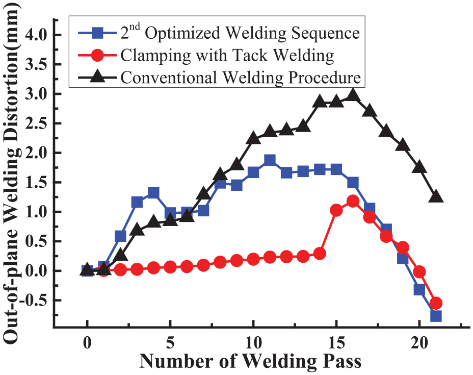
Comparison of evolution and magnitude of overall out-of-plane welding distortion with different assembly techniques.
Conclusion
An effective TEP FE computation with ISM and OpenMP parallel computation was proposed, and employed not only to predict out-of-plane welding distortion during the fabrication of pozidriv type welded structure with rectangular pipes but also to mitigate out-of-plane welding distortion with clamping constraint and welding sequence optimization. The following conclusions can be drawn:
Welding experiment and out-of-plane welding distortion measurement of pozidriv type welded structure with rectangular pipes were both carried out, and magnitude of out-of-plane welding distortion is obviously influenced by welding procedure.
Effective TEP FE computation with ISM and OpenMP parallel computation was proposed, and then employed to predict out-of-plane welding distortion that has a good agreement with measurement results.
Influence of welding sequence on welding distortion was numerically examined, and optimized welding sequence can significantly reduce out-of-plane welding distortion about 38% magnitude, which is clarified with the variation of structural stiffness.
Magnitude of out-of-plane welding distortion reduced with about 56% was examined with experiment and FE computation due to clamping constraint, while non-linear element was presented to consider the springback response after clamping release.
Footnotes
Declaration of conflicting interests
The author(s) declared no potential conflicts of interest with respect to the research, authorship, and/or publication of this article.
Funding
The author(s) received no financial support for the research, authorship, and/or publication of this article.