
Abstract
Miniature gears have important research value and application prospects in micro-scale machinery. The existing manufacturing methods for miniature gears produce spur gears on the micron scale and spur, helical and bevel gears on the millimetre scale. However, there is no mature process for gears on the micron scale for angular transmissions, such as bevel gears. This article reports for the first time the micro-machining of a miniature bevel gear with an external size of 1–2 mm based on a novel gear structure: the bevel line gear. First, a novel manufacturing method, namely the two-step method of nanosecond pulse laser ablation (NSPLA), is proposed. Then, a sample of a miniature bevel line gear is fabricated from 6061 aluminium alloy with a top angle of 90°, external diameter of 1375 μm, tooth number of 3 and average tooth width of 20 μm. Finally, the accuracy of the sample is studied to confirm the practicability of the proposed method.
Keywords
Introduction
Manufacturing of miniature gears
Miniature gears are defined as gears with an external size of 0.1–10 mm, 1 which can be subdivided into meso gears with an external size of 1–10 mm and micro gears with an external size of 0.1–1 mm. Miniature gears can be applied to micro motors, micro and meso gear boxes, 2 medical micro devices, 3 transmission parts in cameras and micro pumps. 4 Miniature gears are key elements of different micro-systems due to their potential advantages of ultra-light weight, small size and compactness, high dimensional accuracy, favourable functional and operating characteristics, long service life and zero backlashes compared to macro gears and their ability to sustain this performance in harsh environments. 5 Reaching these excellent characteristics is the aim of miniature gear research, but some features have not yet been achieved. Reaching high performance depends on the manufacturing processes and technologies, which emphasizes the importance of the manufacturing technologies of miniature gears.
To date, studies on the manufacturing of miniature gears have focused mainly on the processing of involute spur gears. Micro-hobbing 6 and micro-milling 7 are the traditional methods. However, burr problems exist in micro cutting, 8 which makes miniaturization difficult. Advanced methods include local forming, 9 powder metallurgy, micro-metal injection moulding, 10 powder extrusion moulding, 11 and micro electrical discharge machining (μ-EDM). Micro-machining of meso bevel and helical gears has also been reported. Using the powder extrusion process, Kim and Ko 12 made meso helical gears with powder Zn–22 wt% Al with an outside diameter of 2.55–4.348 mm, a module of 0.2–0.3 mm, a tooth number of 12 and a helix angle of 15°. By using the micro wire cut electrical discharge machining(μ-WEDM) process, Chaubey and Jain 13 made meso helical and bevel gears with an outer diameter of8–10 mm and quality of DIN6–7. The review of Chaubey and Jain 1 provides a detailed summary of the manufacturing of meso and micro cylindrical gears and reaches the following conclusion: Most of the existing technologies yield poor quality meso and micro gears, reaching a quality standard of DIN9–12. No additional work has been reported on the fabrication of other types of meso and micro gears, such as worm, non-circular gears, internal gears or splines. 1
In brief, existing micro manufacturing processes cannot achieve the manufacturing requirements of micro bevel gears. The difficulties lie on the complex teeth profiles of involute gears that are designed on the basis of the conjugate surface meshing principle. The spur gear is a special case because its teeth surfaces are parallel to its axis, so a micro spur gear is a type of 2.5D structure, which is why it is easier to be manufactured than other configurations. Helical and bevel gears have more complex teeth profiles but can still be manufactured by powder extrusion and μ-WEDM. However, the component size is limited to a few millimetres, specifically, greater than 2 mm. For other types of miniature involute gears, such as worm gears, internal gears and spiral bevel gears, the existing micro-machining technologies cannot adapt to the processing of their complex 3D surfaces. In other words, there is no mature technology to manufacture miniature gears with outer sizes smaller than 2 mm for the requirement of micro transmissions between intersecting and stagger shafts.
Bevel line gear (LG)
The LG, proposed by Chen et al., 14 is a novel gear based on space-curve meshing theory in which the teeth of the driving LG and the driven LG are a pair of spatial conjugate curves, namely the driving contact curve and the driven contact curve. 15 The unique profile of the LG reduces the difficulties in micro-machining, which provides a theoretical basis for the research of possible new miniature gear machining technologies. The LG also has disadvantages: The meshing is in the form of point contact, so this gear type cannot transfer a large force, and the tooth profile is easy to wear, but these problems are relatively minor in micro and miniature transmissions.
In preliminary studies, three types of contact curve pairs of LGs for rotary transmission between two intersecting shafts are proposed: the circular helix-conical spiral; 16 the Archimedes spiral-conical spiral; 17 and a pair of conical spirals. 18 The bevel LG pair with a pair of conical spirals as its contact curve pair has the following advantages: First, it can realize the transmission between the intersecting axis in the pure rolling state; 18 second, the difficulties of miniaturization are smaller than those of the involute bevel gear; third, the structures of the driving and driven gear wheel are consistent and can be processed by the same process.
The detailed design philosophy of the bevel LG pair mechanism can be found in Chen et al. 18 To get an intuitive understanding of bevel line gear pair transmission, please refer to the supplemental material. Here, the basic equations to be used in this article are briefly introduced.
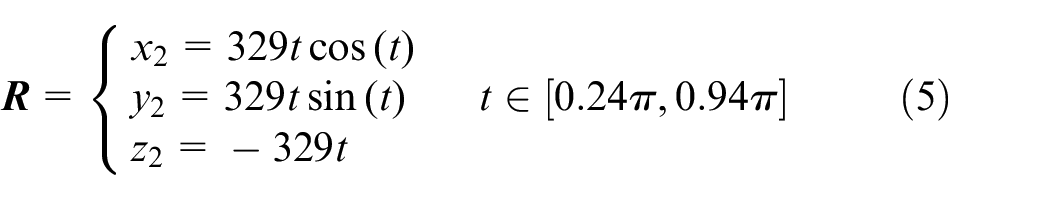
Considering only the external gearing, the parametric equations of the driving and driven contact curves,
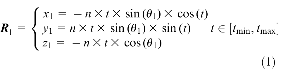
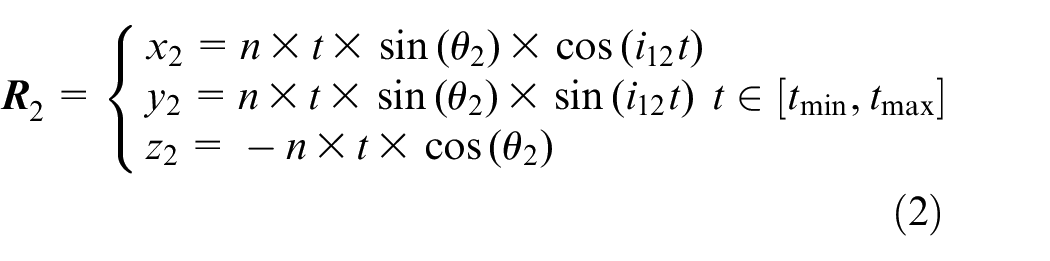
where t is a parameter representing the angle at which
Layer-by-layer nanosecond pulse laser ablation (NSPLA) method
Pulse laser ablation (PLA) is capable of manufacturing micro structures from metals, ceramics and polymers. 19 Researchers have used heat conduction and molecular dynamics 20 to describe the physical process of laser ablation, including the material removal mechanisms and the formation of plasma shielding. In the case of NSPLA of metal and metal-like materials, the target material is removed based on the thermal effect, and the main mechanisms are melting, evaporating and phase explosion.21,22 Literatures23–25 established material removal models of NSPLA based on normal evaporation and phase explosive. Xing et al. 26 explored the influence of the combination of laser power and scanning speed on the roughness of the bottom of the ablation groove and improved the parameter interval; Sivarao et al. 27 and Mandal et al. 28 used the response surface method (RSM) or Tachi method to select better parameters for processing grooves with smooth bottoms. These results provide valuable references for parameter selection in the NSPLA process in this article to obtain better processing effects.
When processing 3D structures, the layer-by-layer NSPLA method is applied. Its basic principle is to slice the target 3D structure, and the material is removed layer by layer according to the cross section of the slice. The precision of the horizontal pattern is usually very high, so the errors usually come from the height direction. As a result, the processing quality of the 3D structure is based on precise control of the ablation depth of each layer.
Among the many micro-machining methods, the layer-by-layer NSPLA method has the following characteristics: compared to micro cutting, it is a non-contact process, so the workpiece does not need clamping; compared to μ-WEDM, μ-EDM, micro cutting and so on, its machining tool, which is the laser beam, can be easily controlled and located and does not undergo wear; compared to LIGA, μ-EDM, micro extrusion and so on, the material adaptability is very wide. One can select laser parameters such as laser wavelength according to the target material’s optical properties. Compared to picosecond or femtosecond PLA, NSPLA has a lower power density, larger heat affected zone (HAZ) and lower machining accuracy, but it has a comprehensive advantage of efficiency, accuracy and economic factors in manufacturing micro parts with a feature size range of 0.1–1 mm. Therefore, the layer-by-layer NSPLA method is suitable for manufacturing miniature bevel LGs.
Two-step NSPLA method for miniature bevel LGs
In this part, the modelling of miniature bevel LG teeth and wheel body based on the characteristics of NSPLA are studied, and the two-step method of NSPLA manufacturing of miniature bevel LGs is proposed.
According to section ‘Manufacturing of miniature gears’ the existing technologies cannot be adopted for the manufacture of bevel gears with dimensions below 2 mm. This is because the tooth profile of the involute bevel gear is a complicated space surface, which is difficult to miniaturize. However, the tooth of the LG is a space cylinder built by a spatial curve, which is a relatively simpler space surface, so the machining difficulty is reduced and miniaturization is easier. A bevel LG is chosen to be manufactured in this article.
As discussed in section ‘Layer-by-layer nanosecond pulse laser ablation (NSPLA) method’, the layer-by-layer NSPLA method can be applied to 3D structure processing. If the overall workpiece is sliced and manufactured layer by layer, the quality of the whole structure is the same. The gear has a special manufacturing requirement: Only the accuracy of certain areas of the workpiece – the gear teeth – needs to be guaranteed, and the processing quality requirements of other areas, for example, the wheel body, are very low. Therefore, the overall layer-by-layer removal is not the most suitable method. It is necessary to re-design the machining process according to the characteristics of the target structure.
The disadvantages of using the overall layer-by-layer machining method to process the bevel LG in this article are as follows: First, it is difficult to ensure the accuracy of the workpiece because the thickness of each removed layer cannot be accurately guaranteed. If an error in the height direction occurs, the conical helix that lies on the tooth profile will not lie on the cone enveloping surface with a given cone angle, resulting in transmission error. Second, it is hard to measure the errors of the workpiece. If the conical helix is obtained directly, it is difficult to determine whether it lies on the given envelope cone surface.
As a result, according to the structural characteristics of the bevel LG, a two-step layer-by-layer NSPLA method is put forward to apply the layer-by-layer removal method twice. In the first step, a circular cone is manufactured. The influences of the parameters on the conical surface are studied to ensure the accuracy of the envelope cone surface of the workpiece; in the second step, the material in the side clearance of the teeth is removed to form the teeth profile.
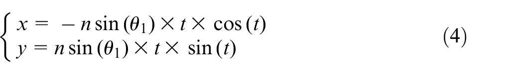
Essentially, a conical spiral, which is the contact curve of the bevel LG, is obtained through the intersection of a conic surface and a cylinder with an Archimedes spiral as the baseline. The two-step method of NSPLA superpositions the machining process of the conic surface described by equation (3) and that of the cylindrical surface described by equation (4). Where
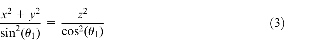
In step 1, the enveloping conic surface of the miniature bevel LG described in equation (3) needs to be manufactured using the layer-by-layer method, as shown in Figure 1.
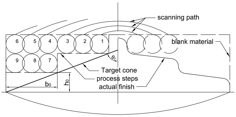
Scanning strategy of a conic surface.
In step 2, the material other than the teeth on the conic surface continues to be removed. Figure 2 shows the geometry constructions of the driving and driven miniature bevel LGs assembled. The dashed area indicated by diagonal lines is the tooth space from where the material is removed.
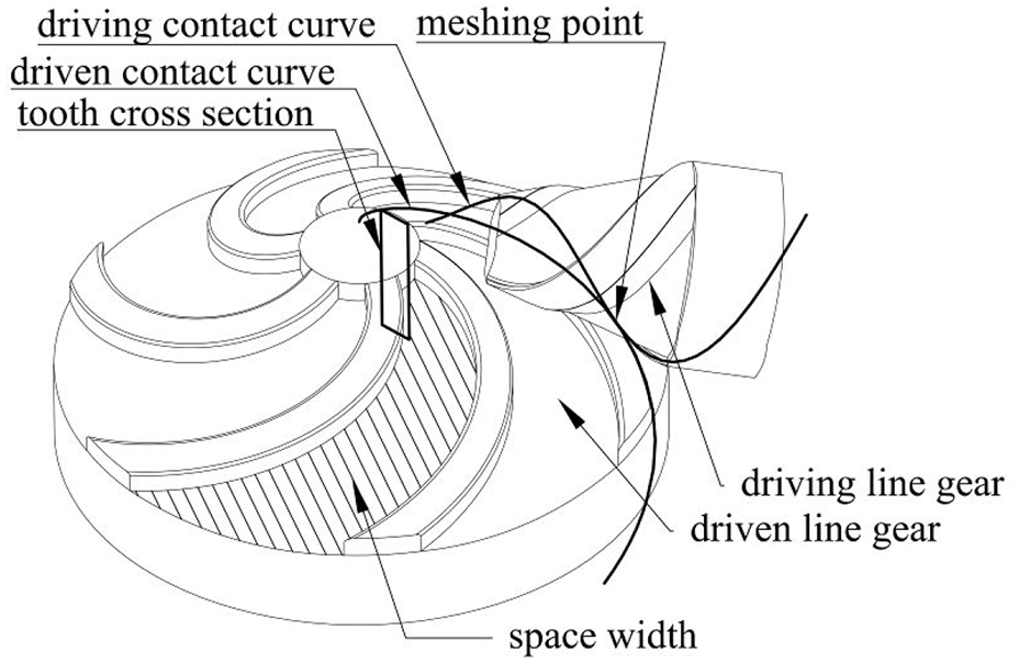
Geometry construction of miniature bevel LG.
In brief, a micro circular cone is manufactured in the first step of the process; gear teeth are manufactured in the second step of the process. This is named the two-step method of NSPLA. To get an intuitive understanding of the proposed two-step method, please refer to the supplemental material.
The two-step method of NSPLA has two advantages: First, the scanned area conforms to the geometric features of the structure, which simplifies the scanning process; second, it is easy to characterize the shape errors of the conical helix, which is decomposed into the shape error of the enveloping cone and Archimedes screw. As a result, the machining accuracy is easy to guarantee.
Manufacturing experiments
In this part, manufacturing experiments are carried out for a design example of a miniature bevel LG. Sections ‘Step 1: Manufacturing of the micro circular cone’ and ‘Step 2: Manufacturing of the teeth’ correspond to the two steps of the manufacturing method.
The experimental set-up is as follows: The laser beam is generated by a Q-switched fibre laser with a wavelength of 1064 nm, pulse duration of 100 ns, repetition frequency of 20 kHz and an average power of 20 W. The transmitted beam is focused on the target surface by using a set of lenses. The repetitions of the X and Y scanners are
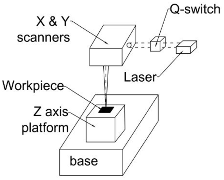
Structural diagram of laser marking machine.
Step 1: Manufacturing of the micro circular cone
The requirement of micro cone manufacturing is to ensure the top angle and contour of the conic surface. By means of the experimental method, the relationship between the processing parameters and the semi-top angle of the processed cone can be obtained. Then, appropriate processing parameters can be selected according to the top angle of the designed target bevel LG.
In the experiments, the bottom surface of the circular cone has a diameter of 1375 μm, and the conic surface is fitted by 10-step stair profiles. Through many comparative experiments, the filling mode of the scanning path with the best effect is obtained, which is the two-way reciprocating vertical scanning mode with a hatch of 5 μm. The maximum laser power is 20 W, and the six groups of laser power values selected in the following experiments are 20%, 35%, 50%, 60%, 70% and 80% of the maximum value. The five groups of scanning speed values are 1000 mm/s, 750 mm/s, 500 mm/s, 250 mm/s and 100 mm/s. Because the pulse repetition frequency in this experiment is a fixed value of 20 kHz and the laser spot diameter is 40∼50 μm, the pulse overlaps correspond to scanning speeds of 0%, 25%, 50%, 75% and 90%. In total, there are 30 combinations of parameters. Each combination is repeated three times in the experiments. The focus position is on the surface of the slab. According to a pilot experiment, the ablation depth is not significantly affected within 2 mm of the laser spot defocus. The results are shown in Figure 4, and as seen in Figure 5, the height of the manufactured cone is within 1 mm, so the feed speed in the vertical direction is set to zero in the experiments.
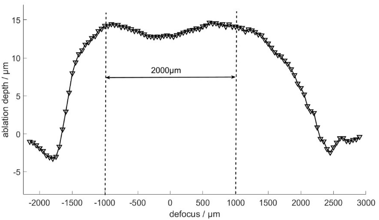
Ablation depth – defocus.
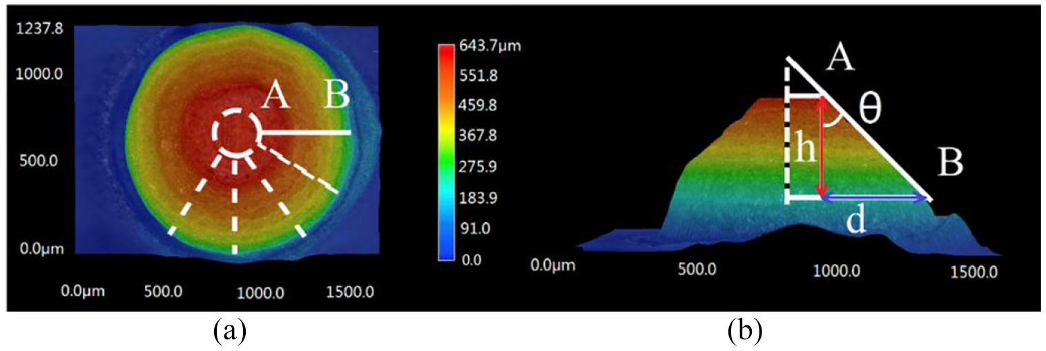
Demonstration of circular cone measurement: (a) Top view. (b) Side view.
Figure 5 shows one of the results of the processed circular cones. The measurement method of the average semi-top angle
Figures 6 and 7 show the relationship between the semi-top angle and the laser power and the relationship between the semi-top angle and the scanning speed (pulse overlap as well), respectively. The data are fitted by a cubic polynomial.
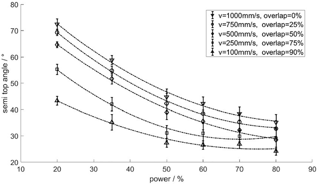
Semi-top angle of micro circular cones – laser power.
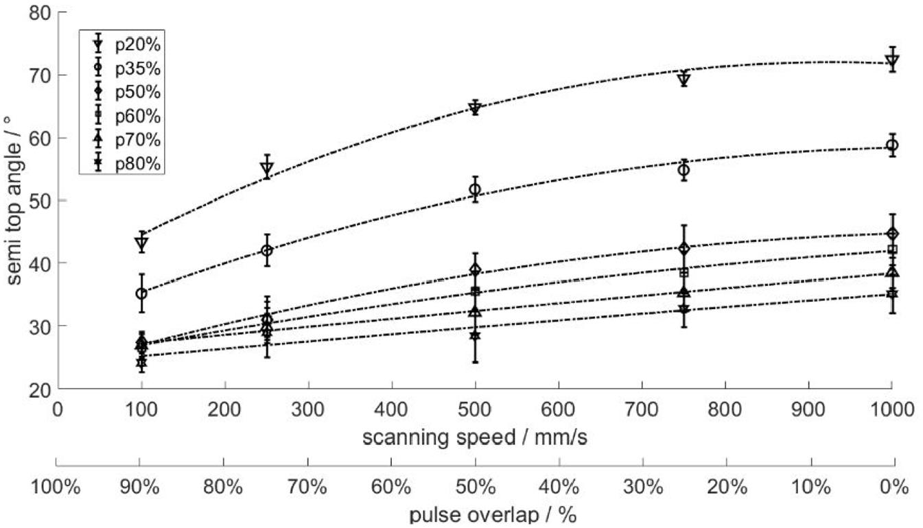
Semi-top angle of micro circular cones – scanning speed.
The standard deviation of the semi-top angle can show the symmetry of the cone that a lower standard deviation represents a cone with better symmetry. Figures 8 and 9 show the standard deviation of the measured data of the semi-top angle, where a lower standard deviation represents a cone with better symmetry. Figure 8 shows a general trend in which the cone symmetry increases as the laser power decreases; Figure 9 shows that at a small scanning speed and larger pulse overlap, the cone symmetry is better.
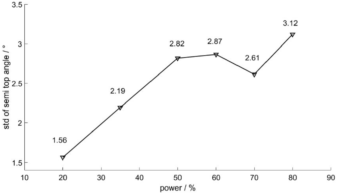
Standard deviation of semi-top angle – laser power.
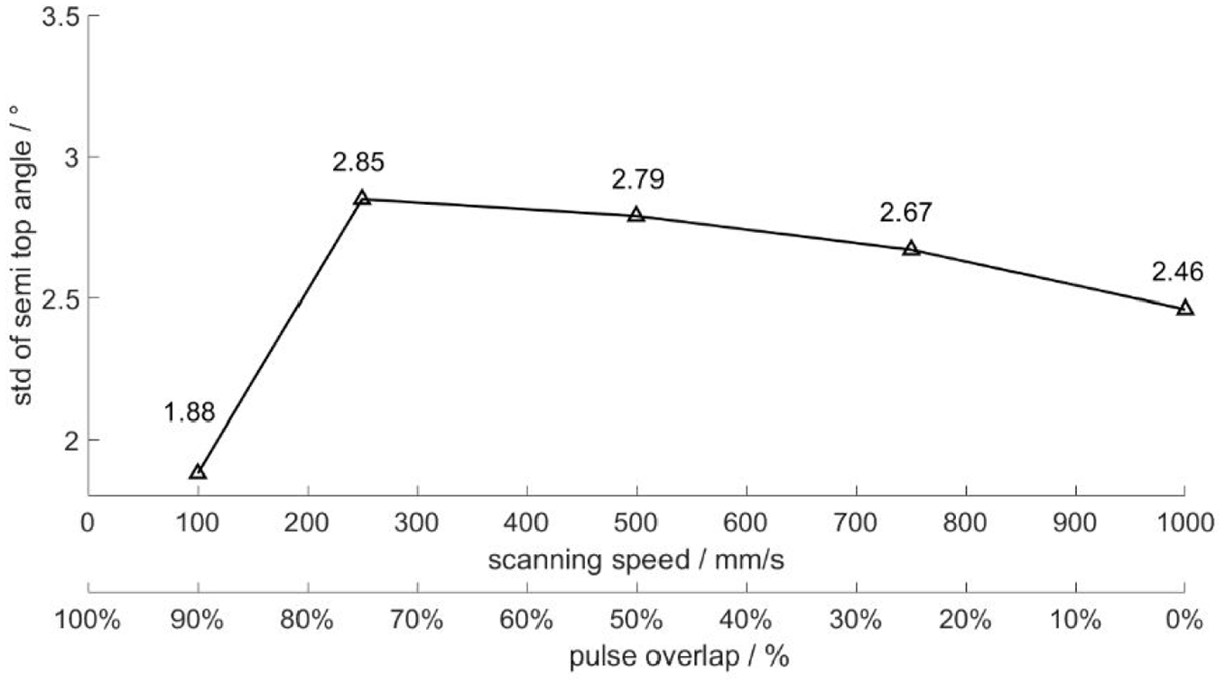
Standard deviation of semi-top angle – scanning speed.
Conclusions are drawn from above that by selecting the proper process parameters, the layer-by-layer NSPLA method is capable of manufacturing micro cones with semi-top angles within a range of
Then, an example of machining a miniature bevel LG with a suitable size using NSPLA is presented. The semi-top angle of the envelope cone of the bevel LG is 45°; the number of teeth is 3, the thickness of the tooth profile is
According to the fitting results of the experimental data, three combinations of scanning speed and laser power parameters can be selected for machining a cone with a semi-top angle of 45° as follows: 500 mm/s, 42.89%; 750 mm/s, 46.62%; and 1000 mm/s, 49.81%. The three laser power parameters are relatively close, so all three combinations of the parameters are used in the manufacturing process. Three corresponding circular cones were manufactured, and their cone angle deviation
Deviation of the processed cones.
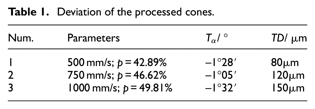
The values of
Step 2: Manufacturing of the teeth
The basic requirements of manufacturing the LG teeth are as follows: to remove the material in the tooth space and to ensure the integrity and precision of the contact curve at the same time. The following parameters are set as the parameters of machining the teeth: 30% of the maximum laser power; scanning speed of 500 mm/s; two-way reciprocating vertical scanning mode with a hatch of
Figure 10(a) is the 3D model of the target workpiece to be machined, and Figure 10(b) is the surface morphology of the machined workpiece measured by the optical profilometer. A comparison of Figure 10(a) and (b) confirms that the surface morphology of the workpiece is consistent with the expected morphology.
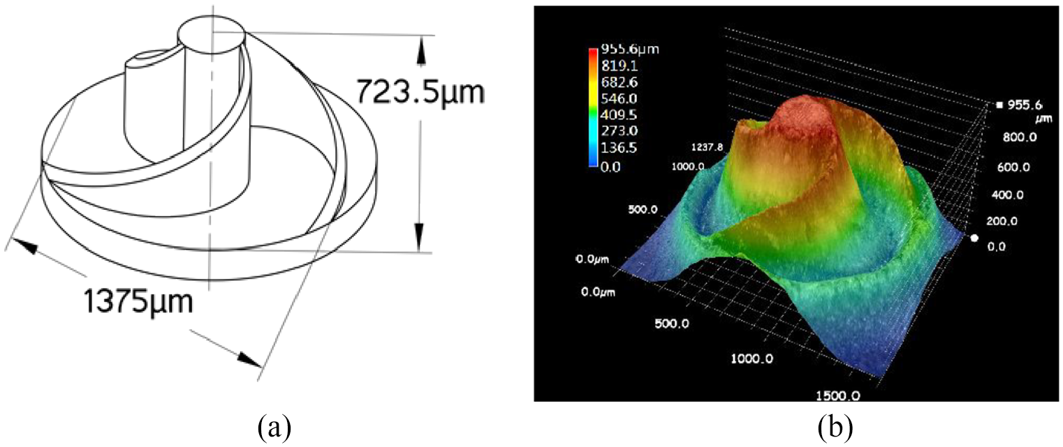
Miniature bevel LG workpiece: (a) 3D model of workpiece. (b) Optical profiler picture of workpiece.
The results of the shape error of the teeth profiles are shown in Figure 11. The three contact curves are shown as yellow, blue and red solid lines. The maximum profile deviation of the contact curve is
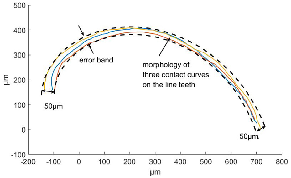
Shape error of the contact curve.
Figure 12 shows SEM images of the miniature bevel LG. Figure 12(a) shows that the overall external diameter of the sample is approximately 1.4 mm, and the symmetry and integrity of the sample are good. Figure 12(b) shows the profile of a bevel LG tooth. Figure 12(c) shows the morphology of the tooth surface. The average width of the tooth is 20 μm. As shown in Figure 12(c), in the NSPLA process, random debris is formed by spattering the molten material to the tooth surface. The debris reduces the surface accuracy and affects the stability of gear transmissions. The maximum height of the debris is 23.6 μm. The surface roughness values of the tooth are
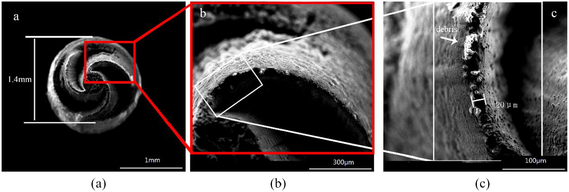
SEM image of miniature bevel LG sample: (a) Overall image. (b) Detailed view of a tooth profile. (c) Detailed view of the surface morphology.
The LG is a novel gear, so its accuracy standards have not yet been established. Therefore, an evaluation was made of the machining accuracy of the LG by referring to the accuracy standards of conic surfaces and the accuracy standards of involute gears. According to the shape characteristics and two-step processing order, the shape error of the bevel LG teeth can be divided into the following two parts: the shape error of the envelope cone and the shape error of the projection of the conical spiral on the horizontal plane. Specifically, the errors in machining the geometry construction are described in equations (3) and (4). The former can refer to the shape accuracy standard of the circular cone surface, and the latter can refer to the standard of the involute gear. The three teeth profiles in Figure 11 are rotated and superimposed in the same position so that the form error
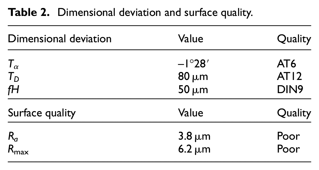
The results of dimensional deviation and surface quality of the miniature bevel LG are shown in Table 2. The tooth profile deviation
Dimensional deviation and surface quality.
Conclusion
In this article, a novel micro-machining method is proposed to manufacture miniature bevel LGs with external sizes of 1–2 mm. Specifically, according to the design theory of LGs, this article briefly introduces the meshing model of bevel LG pairs. Then, the structure of the miniature bevel LG is proposed along with its two-step method of NSPLA.
A summary of the main conclusions is as follows:
A two-step method of NSPLA for miniature bevel LGs was proposed, including the first-step manufacturing of circular cones and the second-step manufacturing of LG teeth.
A sample of 6061 aluminium alloy miniature bevel LG is fabricated using nanosecond pulse laser equipment with a taper angle of 90°, external diameter of 1375 μm, teeth number of 3 and average tooth width of 20 μm, which verifies the practicability of the two-step NSPLA method.
In the future, further study is needed to improve the machining accuracy and surface finish of miniature bevel LGs. For example, the diameter deviation of the enveloping cone
Footnotes
Appendix 1
Declaration of conflicting interests
The author(s) declared no potential conflicts of interest with respect to the research, authorship, and/or publication of this article.
Funding
The author(s) disclosed receipt of the following financial support for the research, authorship, and/or publication of this article: This work was supported by National Natural Science Foundation of China (No. 51575191), the Fundamental Research Funds for the Central Universities (No.2017B0071, No. 2018PY12) and 2019 Guangzhou technology project (No.201904 010368).
Supplemental material
Supplemental material for this article is available online.
References
Supplementary Material
Please find the following supplemental material available below.
For Open Access articles published under a Creative Commons License, all supplemental material carries the same license as the article it is associated with.
For non-Open Access articles published, all supplemental material carries a non-exclusive license, and permission requests for re-use of supplemental material or any part of supplemental material shall be sent directly to the copyright owner as specified in the copyright notice associated with the article.