
Abstract
This study focused on determining the residual stress of SAE 52100 hard-turned steel. The objective was to evaluate and compare the effects of the cutting-edge geometry and cutting parameters (cutting speed, feed rate, and cutting depth) on the residual stresses of three different conventional inserts: S-WNGA08 0408S01020A 7025, T-WNGA08 0408T01020A 7025, and S-WNGA432S0330A 7025. Tests were performed on 60 samples of SAE 52100 hardened steel with an average hardness of 58.5 HRC. The circumferential residual stresses of the samples were measured by X-ray diffraction. A full factorial design of experiments with three factors and two levels each with two central points and a replicate was used for a statistical analysis. The most significant results were as follows: For all inserts, the measured residual stresses were compressive, which extended the tool lifespan. The residual stresses of the Type-S inserts were significantly influenced by the cutting speed and depth, and those of the Type-T insert were significantly influenced by the feed rate and cutting depth. In addition, the residual stresses of the insert 3 were more compressive than those of the other two types of inserts. In other words, residual stresses are more compressive for inserts with larger chamfer angles even as the principal residual stress profiles were all compressive. This work has also shown that it is possible to determine a significant statistical relationship between cutting forces and residual stresses, allowing force measurements to predict the residual stress without any information on process parameters.
Introduction
Technological advances have enabled companies to manufacture products with superior quality rapidly, which, in turn, has allowed engineers to adapt different methods for performing several tests to maintain the same surface quality of manufactured products, 1 mainly in hard-turning process that requires fewer operations when compared to the grinding process, saving time and energy.2,3 Hard turning has several advantages over the grinding process, especially in the machining of complex profiles and in addition, induces compressive residual stresses in the workpiece as opposed to tensile residual stresses induced by the grinding process, which increases the lifespan of the workpiece. Kumar et al. 4 listed the main products that have been manufactured by this process, which include automotive gears, axes, inner and outer race bearing. On the other hand, hard turning can be performed by high-speed machining (HSM), where cutting speeds reach 250 m/min with ceramic or CBN inserts and without cooling, and can improve machined surface finish, enable machining of difficult-to-cut materials, and offer high productivity. 5 Chip formation also differentiates the conventional turning process from HSM; in the conventional process, the chip is less fragmented than in HSM. 6
Surface integrity has been the focus of numerous studies over the years. According to Pusavec et al. 7 Sedighi et al. 8 and Pan et al., 9 roughness, hardness, residual stress, among others, are considered characteristics of surface integrity of a material, determining its functionality and fatigue life. For Shaw, 10 the material performance characteristics are generally sensitive to surface integrity, including: fracture resistance, fatigue strength, corrosion rate, tribological behavior, magnetic properties, and dimensional stability. This final piece condition is the result of a process that involves plastic deformation, rupture, elastic recovery, heat generation, vibration, residual stress, and sometimes chemical reactions. 11 The effects of machining cause influences on the parts that can be grouped under three conditions: 12 topographic characteristics, change in mechanical properties, and metallurgical state. In addition to the machining conditions, Sharma et al. 13 and Rath et al. 14 described that the deterioration of surface quality during machining is directly related to the progression of tool wear. According to ASM International, 15 almost all fatigue failures begin at the surface, so surface finish and stress state can have a profound effect on fatigue strength. The friction generated during the machining, together with the low thermal conductivity of many materials, causes excessive heating of the tool, this consequently results in plastic deformation and excessive wear of the tool 16 and also removal of its topcoat. In the hard cutting, wear mechanisms observed are abrasion, fracture, plastic flow, adhesive and tribo-chemical wears 17 and these phenomena lead to some undesirable consequences such as increased cutting forces and residual stress and, consequently, low productivity, as well as increased energy consumption.18,19 High surface roughness values, for example, shorten the lifespan of a workpiece 20 owing to fatigue and increase the tensile residual stresses, and can also shorten the lifespan of the workpiece under varying loads over time.21–25 Tensile stresses generated in a material create favorable conditions for fatigue failure of the part,23,26 and accelerate the initialization and growth of micro-cracks. 27 Optimization of cutting parameters through empirical, analytical, and statistical methods can significantly improve the overall efficiency of the machining process. 28
Safari et al. 29 investigated the machinability of 55Cr3 steel in the turning process of 55Cr3 steel, highlighting the surface roughness variation by using the Taguchi method. Ventura et al. 30 investigated the effect of cutting edge geometries in the hard turning residual stress and found that the higher compressive residual stress in the subsurface and deeper affected zone were due to the geometries with large contact length. Revel et al. 31 studied residual stresses generated by hard turning of AISI 52100 steel and concluded that compressive residual stresses in the material increase with increasing cutting speed. Suresh et al. 32 presented a review of the state-of-the art research in machinability of hardened steels listing five main factors that can affect residual stress distribution in finish hard machining: insert grade, tool geometry, cutting parameters, tool wear progression, and chemical composition and hardness of workpiece material. Stenberg et al. 33 determined the influence of the feed rate, cutting speed, and rake angle at varying depths on the residual stress by a numerical method. Caruso et al. 34 investigated the effects of machining parameters such as cutting speed, hardness, and tool geometry on residual stress profiles of AISI 52100 hard-machined steel. Navas et al. 35 described the effects of cutting parameters on the surface residual stresses generated in AISI 4340 steel by turning. Bouzid et al. 36 studied the mathematical modeling for turning AISI 420 stainless steel and observed that the depth of cut was the dominant factor affecting the cutting force components. Thiele et al. 37 studied the effects of cutting-edge geometry and work material hardness on the surface integrity of AISI 52100. Anupan and Manas 38 investigated the multi-objective optimization of cutting parameters during dry hard turning of AISI 52100 steel and observed that the radial force is greater than main cutting force unlike conventional turning process. Meddour et al. 39 investigated and modeled the cutting forces and surface roughness when hard turning of AISI 52100. Bouacha et al. 40 analyzed the cutting forces using response surface methodology in hard turning of AISI 52100 bearing steel with CBN tool and 64 HRC. Hua et al. 41 investigated the cutting conditions and cutting-edge preparations for enhanced compressive subsurface residual stress in the hard turning of 52100 bearing steel. They measured a circumferential residual stress of −800 MPa. Pawar et al. 42 when studied the residual stresses during hard turning of AISI 52100 steel with 62 HRC, measured a circumferential residual stress of −1300 MPa. Although there is the statistical method concerning the subject matter, analytical formulations showing the relationship of the cutting force and residual stress were also addressed by authors such as Awan and Mabrouki 43 and Saleem et al. 44
As it can be seen from the literature review, the correlation of process parameters with residual stress has been addressed, but the papers found in the literature usually deal with small variations of these parameters implying that the solutions found can be very particular. In this work, we examined the HSM for hard-turning operations of three conventional inserts and employed a wider range of values of independent variables than those utilized in previous works on hard turning.31,33–37 This enabled us to gain a deeper understanding of the hard turning of SAE 52100 steel and its potential applications. The objective of this work was to study the effects of different configurations of cutting inserts on the residual stress and find a relationship between residual stresses and cutting forces to alternatively predict the residual stress without any information on process parameters.
Methods and materials
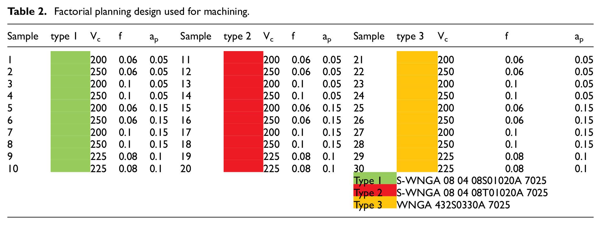
A total of 60 machining tests of SAE 52100 (Table 1) were performed by the full factorial design method with three factors and two levels with two central points. All the machining tests were performed on inserts without pre-existing wear. In the adopted procedure, a single insert was used for the roughing operation and another was used for the finishing operation. Two holders were used: one was mounted with an insert for the roughing operation and the other was instrumented to measure machining forces. The inserts used for machining were limited to only two operations per edge to keep them wear-free.
Chemical composition (wt. %) of the SAE 52100 steel.
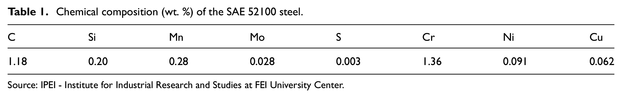
Source: IPEI - Institute for Industrial Research and Studies at FEI University Center.
Table 2 presents the factorial planning design used to perform the tests. The independent variables were (a) cutting speed (vc): 200/225/250 (m/min), (b) feed rate (f): 0.06/0.08/0.10 (mm per revolution), and (c) cutting depth (ap): 0.05/0.10/0.15 (mm). The dependent variables were the residual stress (RS) and the machining forces. Values of vc, f, and ap utilized in this study were those recommended by the manufacturer of the inserts, and the machined length of each test workpiece was 30 mm.
Factorial planning design used for machining.
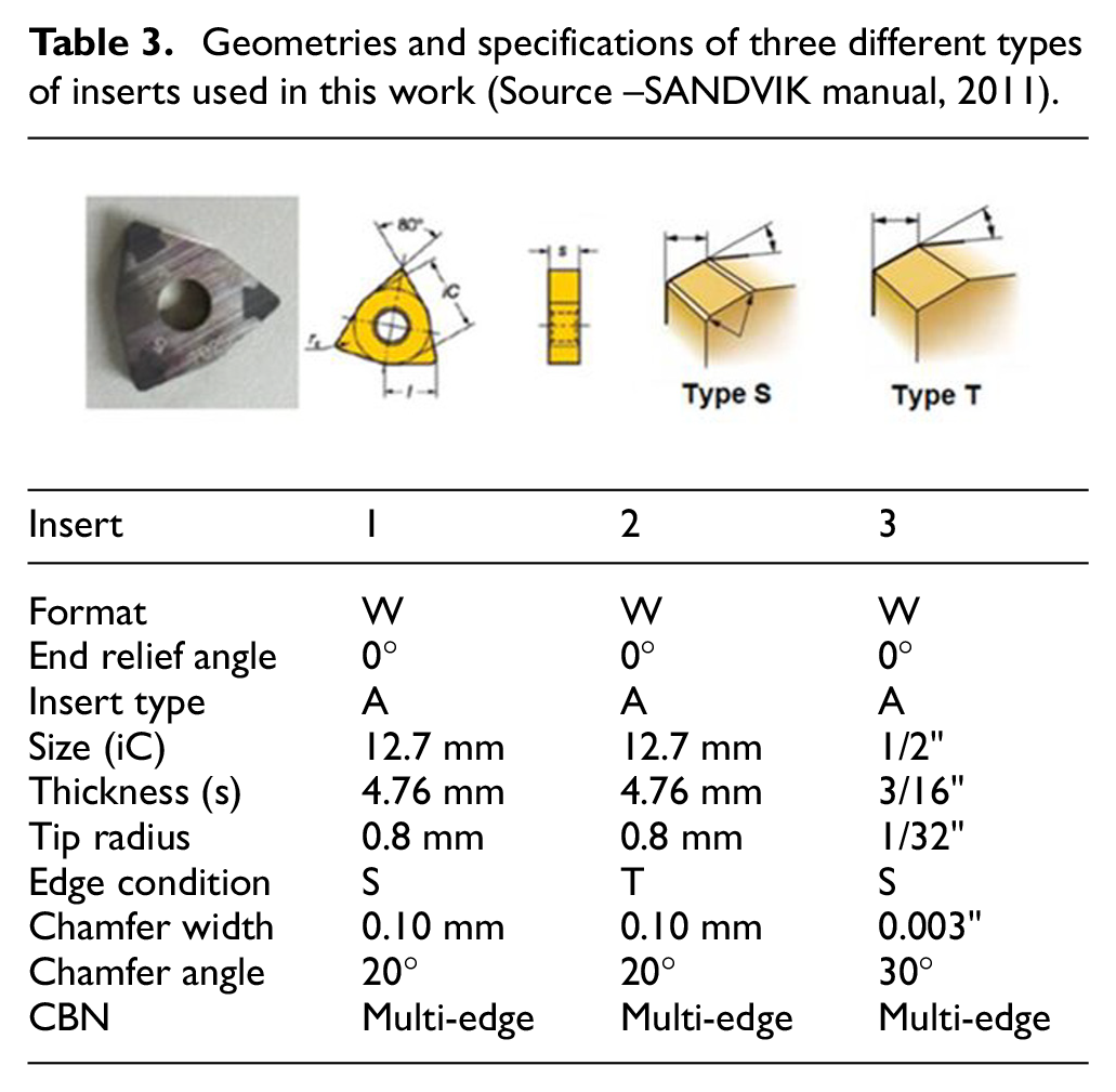
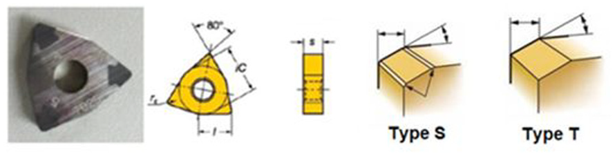
The experiments were performed on a Romi Centur 30D computer numerical controlled (CNC) lathe under dry conditions. Three types of CBN inserts (Table 3) —S-WNGA 08 04 08S01020A 7025, T-WNGA 08 04 08T01020A 7025, and WNGA 432S0330A 7025 — manufactured by Sandvik™ Coromant were used as the cutting tools. In order to ensure cutting stability, each experiment was performed using a new sharp insert.
Geometries and specifications of three different types of inserts used in this work (Source –SANDVIK manual, 2011).
A total of 60 round specimens of 52100 steel, each with a diameter and length of 25.4 mm and 80 mm, respectively, were used for the experiments. The round bars were quenched at 845 oC and tempered at 220 oC during 1.5 h, and their average hardness was 58.5 HRC.
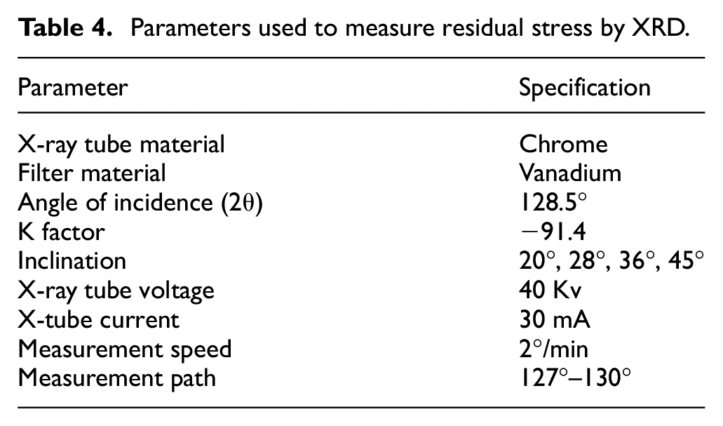
A piezoelectric PCB-260A02 model force transducer and the signal conditioner PCB-441A42 from PCB Piezotronics were used to record and measure the three cutting forces, that is, feed force (Ff), cutting force (Fc), and radial force (Fp), during machining. For a comprehensive study, wider ranges of values of the cutting depth and feed speed than those considered in previous studies on the hard-turning operation were selected in the present study. The residual stresses (RS) were measured using the Shimadzu XRD-7000 diffractometer in the circumferential direction (i.e. along the cylindrical surface of the sample). The parameters used for the residual stress measurement are listed in Table 4 and the technique applied was sin2ψ.45–48 The Blind Hole Method has been used to measure the residual stress profile of the parts. The Blind Hole Method is weak relative to measurements of residual stresses on the surface of a body. This is explained by the hole methodology for applying a residual stress calculation by some integrative method. The X-ray Diffraction and Blind Hole methods are of different natures, that is, the first measures residual stresses through the displacement of crystallographic planes and the second measures from a 1.6 mm cutter; thus it is expected that the measured values are not equal, however, they must be within the same order of magnitude as measured in this research.
Parameters used to measure residual stress by XRD.
Results and discussion
This section describes the influence of machining parameters on circumferential residual stress (RS) and cutting forces (Fc, Ff and Fp) (Table 5), where Fc is the tangential force, Ff is the feed force, and Fp is the passive force. For analysis of the test results, a factorial planning design was fitted to the results of the tests and their replicates with a 95% confidence interval.
Results of average circumferential residual stresses (RS) (MPa), cutting forces Fc (N), feed forces Ff (N) and radial forces Fp (N), for the factorial planning.
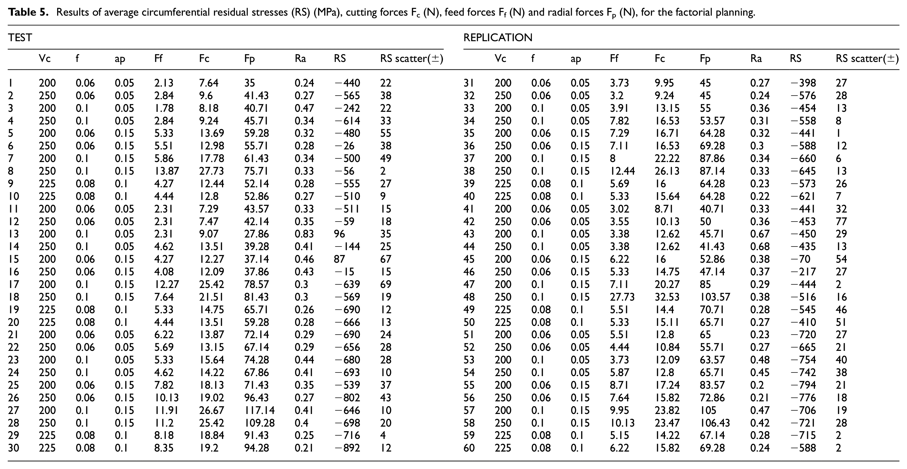
The experimental values of this research, Table 6, agree with the values obtained by Anupan and Manas, 38 Meddour et al., 39 Bouacha et al., 40 Hua et al., 41 and Pawar et al. 42 The slight variations are due to the different values of the cutting parameters or hardness of the steels employed.
ANOVA results for circumferential residual stresses and regression equation in uncoded units.
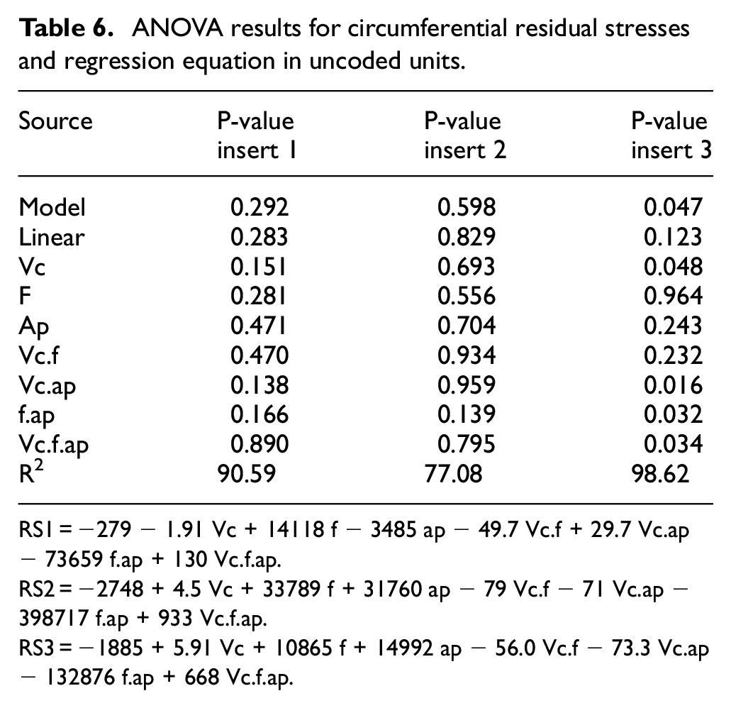
RS1 = −279 − 1.91 Vc + 14118 f − 3485 ap − 49.7 Vc.f + 29.7 Vc.ap − 73659 f.ap + 130 Vc.f.ap.
RS2 = −2748 + 4.5 Vc + 33789 f + 31760 ap − 79 Vc.f − 71 Vc.ap − 398717 f.ap + 933 Vc.f.ap.
RS3 = −1885 + 5.91 Vc + 10865 f + 14992 ap − 56.0 Vc.f − 73.3 Vc.ap − 132876 f.ap + 668 Vc.f.ap.
Table 5 shows that the circumferential residual stresses of all 60 samples were negative. This result shows that the influence of the thermal processes on the circumferential residual stresses was insignificant compared to that of plastic deformation. Observation of the respective macrographs, such as that shown in Figure 1, revealed that white-layer formation did not occur in any of the samples. It is known that white-layer formation is the result of re-tempering of a material in a small surface layer and that it leads to the generation of tensile circumferential residual stresses on the material surface. This knowledge is consistent with the results of Hosseini et al. 49 who reported the presence of tensile circumferential residual stresses in the thermally induced white layer
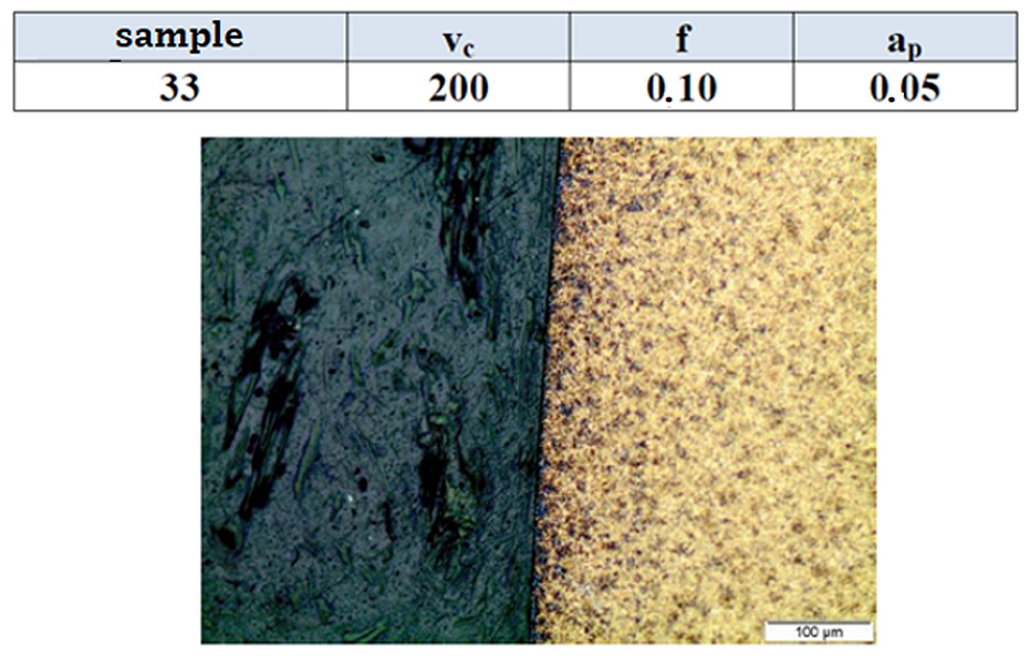
Macrograph showing absence of white layer of part subjected to treatment 29 of the factorial planning (Table 6).
An analysis of variance (ANOVA) (Table 6) revealed that for all three types of inserts, circumferential residual stresses were influenced mainly by the feed rate, cutting depth, and cutting speed. These factors may trigger thermal processes and microstructural transformations and produce mechanical strains; this would consequently result in non-uniform deformations, which, in turn, would lead to the generation of residual stresses. The ANOVA of inserts 1 and 2 did not show statistical significance of 5% indicating that other independent variables should be included in the experimental design, probably the temperature. On the other hand, we could observe that the insert 3 presented statistical significance of 5% when the respective ANOVA was elaborated. This is probably due to the low influence of thermal effects on the metal–insert contact zone as well as phase transformations. Nevertheless, the determination coefficients R2 of the three inserts resulted in high values, respectively 97.35%, 77.08%, and 98.62% indicating that the experimental values are well adjusted to the response surfaces.
The parameters that most influenced the circumferential residual stresses for the insert 1 were the interaction between the cutting speed and the cutting depth and the cutting speed itself. The circumferential residual stresses for the insert 2 were influenced by the interaction between the feed rate and the cutting depth. The circumferential residual stresses for the insert 3 were influenced by the interaction between the cutting speed and the cutting depth. Some key observations were as follows: the higher the feed rate. the higher was the strain rate; the higher the cutting speed, the higher was the temperature, which resulted in changes in the residual stress; higher temperatures facilitated plastic deformation during cutting, as a result of which a more compressive circumferential residual stress was generated on the surface; a higher feed rate resulted in severe non-uniform deformation. In the case of the insert 2, the higher the feed rate, the higher was the compressive circumferential residual stress. In the case of the insert 3, an increase in the cutting speed caused an increase in the compressive circumferential residual stress.
Figures 2–5 show the residual stress distributions in the circumferential direction, the radial forces, the feed forces, and the radial forces, respectively, for all three types of inserts subjected to different treatments. In the circumferential direction, at low values of the feed rate and depth of cut, the residual stress decreased from −242 to −640 MPa as the cutting speed increased from 200 to 250 m/min; that is, the circumferential residual stresses became more compressive and the radial force simultaneously increased. This probably occurred because the plastic deformation of the samples during machining was more dominant than the thermal effects on the samples. Moreover. at high cutting speeds, the removed bits of material absorb most of the generated heat. This agrees with the results of Revel et al. 31 On the basis of this knowledge, we conclude that the maximum compressive residual stress occurred in the subsurface between depths of 0.05 and 0.15 µm.
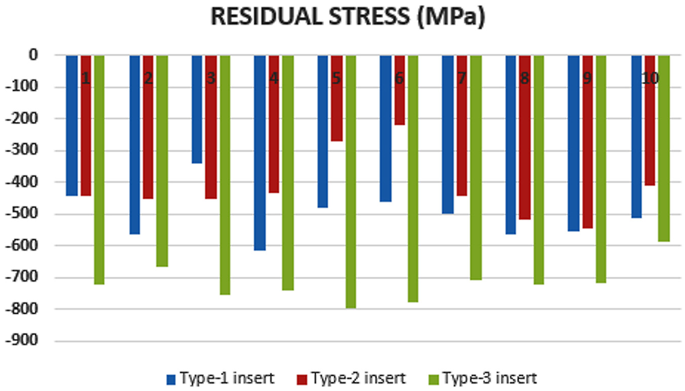
Average circumferential residual stresses for the three types of inserts under various treatments.
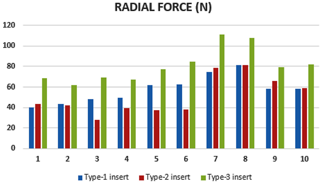
Radial forces for the three types of inserts under various treatments.
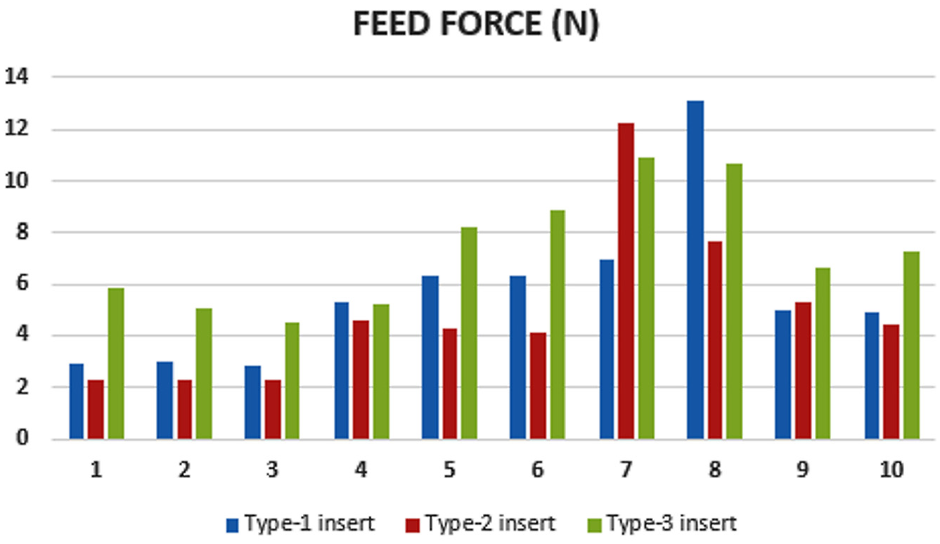
Feed forces for the three types of inserts under various treatments.
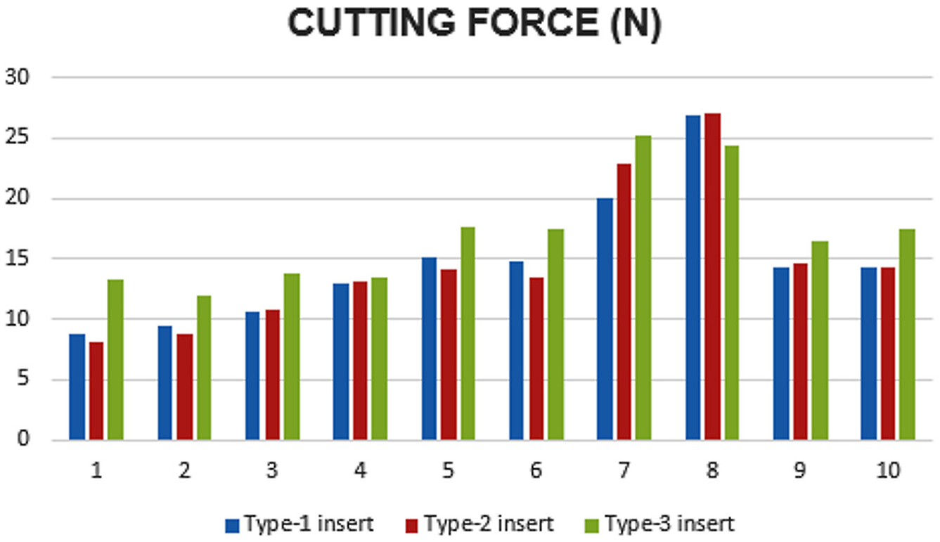
Cutting forces for the three types of inserts under various treatments.
The insert 3 generated the highest compressive residual stresses in the material, as can be seen in Figure 2. This result is supported by the observation of the highest radial forces in the case of the insert 3 in Figure 3. This induced large plastic deformations and, consequently, large compressive circumferential residual stresses in the sample. On the other hand, as can be seen from Table 3, the chamfer angle of the insert 3 (30°) is larger than that of the insert 1 and insert 2 (20°); as a result, larger feed forces are imposed in the case of the insert 3, as shown in Figure 3, and this result justifies the higher compressive residual stresses generated by this insert that causes greater feed and cutting forces, as shown in Figures 4 and 5, justifying the more compressive values of the circumferential residual stresses.
The residual stress profiles were measured in the circumferential and radial directions up to a depth of approximately 0.45 mm (Figure 6) by the hole-drilling method using the SINT MTS3000 system. The sample that was evaluated was the one subjected to treatment 29, which represented the central point of the factorial design for the insert 3. The goal was to observe the occurrences in the subsurface of the machined metal in terms of the residual stresses and to establish the correlations of the residual stresses with the cutting parameters.
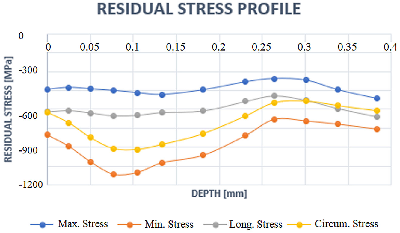
Residual stress profiles of part subjected to treatment 29 of the factorial planning (Table 4).
The first observation made from the measurement results of the residual stress profiles pertains to the values of the compressive residual stress. At depths of up to approximately 40 μm, the circumferential residual stress was highly compressive, with values lower than −600 MPa. These values are also consistent with those determined by XRD observations. The highest measured value of the circumferential residual stress was around −1100 MPa at a depth of 0.1 mm.
It is pertinent to point out the closeness of the values of the principal stresses to the values obtained in the circumferential and radial directions. Consequently, the direction of the highest (more compressive) residual stress was very close to the direction of the vector of the peripheral velocity of the sample. whereas the direction of the lowest (less compressive) residual stress was very close to the direction of the velocity vector of the machining tool or the feed direction.
Considering the machining forces, Tables 7–9 represent the ANOVA results for inserts 1, 2, and 3. For all the inserts, it can be seen with the regressions equations that, as expected, increases in the cutting speed, feed, and depth of cut contribute to increases in their respective forces. This corroborates with the work of Bouzid et al. 36 when turning stainless steel AISI 420. Feed force for insert 1 (Table 7) had the depth of cut as the only variable of some significance. The depth of cut was the most significant parameter for all forces of all the inserts. This can be explained by the fact that hard turning is a finishing machining process.
Feed force ANOVA and regression equation in uncoded units.
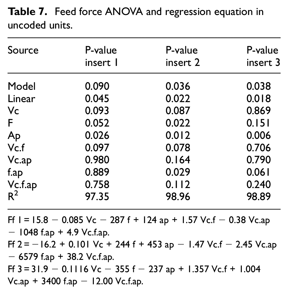
Ff 1 = 15.8 − 0.085 Vc − 287 f + 124 ap + 1.57 Vc.f − 0.38 Vc.ap − 1048 f.ap + 4.9 Vc.f.ap.
Ff 2 = −16.2 + 0.101 Vc + 244 f + 453 ap − 1.47 Vc.f − 2.45 Vc.ap − 6579 f.ap + 38.2 Vc.f.ap.
Ff 3 = 31.9 − 0.1116 Vc − 355 f − 237 ap + 1.357 Vc.f + 1.004 Vc.ap + 3400 f.ap − 12.00 Vc.f.ap.
Cutting force ANOVA and regression equation in uncoded units.
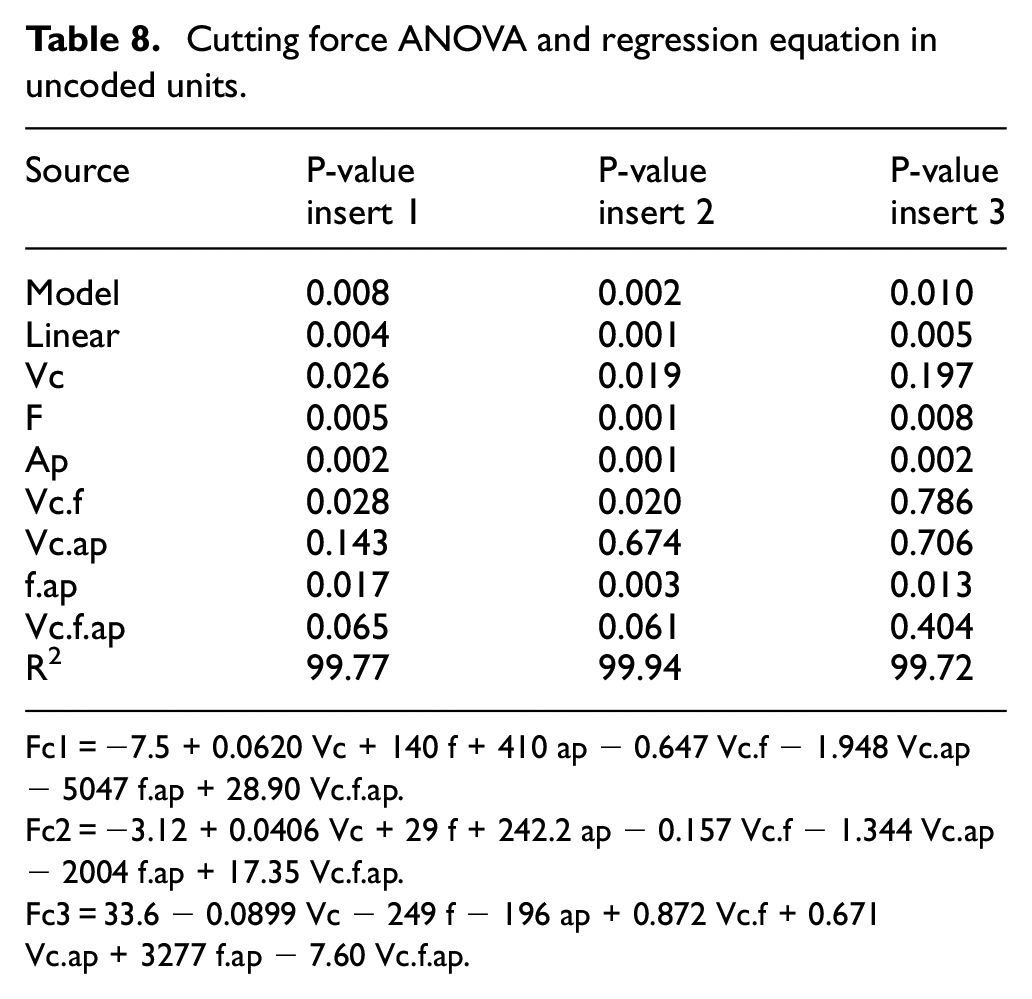
Fc1 = −7.5 + 0.0620 Vc + 140 f + 410 ap − 0.647 Vc.f − 1.948 Vc.ap − 5047 f.ap + 28.90 Vc.f.ap.
Fc2 = −3.12 + 0.0406 Vc + 29 f + 242.2 ap − 0.157 Vc.f − 1.344 Vc.ap − 2004 f.ap + 17.35 Vc.f.ap.
Fc3 = 33.6 − 0.0899 Vc − 249 f − 196 ap + 0.872 Vc.f + 0.671 Vc.ap + 3277 f.ap − 7.60 Vc.f.ap.
Radial force ANOVA and regression equation in uncoded units.
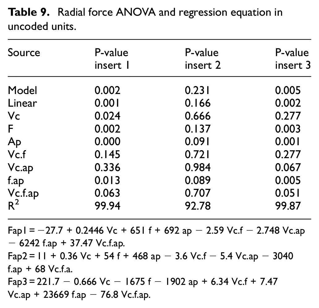
Fap1 = −27.7 + 0.2446 Vc + 651 f + 692 ap − 2.59 Vc.f − 2.748 Vc.ap − 6242 f.ap + 37.47 Vc.f.ap.
Fap2 = 11 + 0.36 Vc + 54 f + 468 ap − 3.6 Vc.f − 5.4 Vc.ap − 3040 f.ap + 68 Vc.f.a.
Fap3 = 221.7 − 0.666 Vc − 1675 f − 1902 ap + 6.34 Vc.f + 7.47 Vc.ap + 23669 f.ap − 76.8 Vc.f.ap.
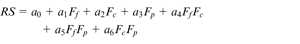
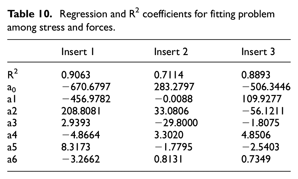
By solving a least square fitting problem among circumferential residual stress and cutting forces it was found a positive correlation between them in the sense of a relatively high R2 coefficient based on the linear function
It means that, if wanted, one may determine a good approximation of the circumferential residual stress solely by means of que cutting forces instead of using que process parameters. The Table 10 shows the regression and R2 coefficients for fitting problem, stress–forces.
Regression and R2 coefficients for fitting problem among stress and forces.
Conclusion
In this work, the residual stress of SAE 52100 hard-turned steel was investigated under the influence of the cutting-edge geometry of the tool and the cutting parameters by considering a wider range of values of independent variables and utilizing three different conventional inserts: S-WNGA08 0408S01020A 7025 (insert 1), TWNGA08 0408T01020A 7025 (insert 2), and S-WNGA432S0330A 7025 (insert 3). We employed statistical experimental planning design for prediction of the effects of the various parameters on the residual stresses. The main conclusions can be highlighted as follows:
For all inserts, the measured circumferential residual stresses were compressive.
Increases in the depth of cut led to an increase in the compressive circumferential residual stresses.
Residual stresses were more compressive for the insert 3.
The principal residual stresses profiles were all compressive.
There was a positive correlation between cutting forces and the circumferential residual stresses.
Footnotes
Acknowledgements
The authors thank Mr. Domenico Landi of Sandvik™ Coromant (Brazil), who kindly donated the inserts used in this work.
Declaration of conflicting interests
The author(s) declared no potential conflicts of interest with respect to the research, authorship, and/or publication of this article.
Funding
The author(s) received no financial support for the research, authorship, and/or publication of this article.