
Abstract
The need for environmental technology of machining is intensifying and is a tough challenge for manufacturing industries. This article investigates the performance of the minimum quantity lubrication in drilling of 6063-T6 aluminum. The experiments were conducted in dry and conventional wet machining and the results compared. Spindle speed, feed rate and point angle are the three parameters considered in this study. High speed steel drilling tools were used and an L8 orthogonal array was chosen for the experimental design. The quality characteristics of dimensional deviation of hole diameter, height of burrs, hole taper, chip thickness, tool wear, cutting power and surface roughness were measured and compared to evaluate the performance of the drilling in minimum quantity lubrication condition. The results presented that the drilling performance has improved in minimum quantity lubrication and demonstrates its capacity as an alternative for dry and wet machining. This article also proposes a feed forward artificial neural network model with a back propagation algorithm to predict the quality characteristics surface roughness and tool wear with chip thickness inputs and cutting power in addition to cutting parameters. The prediction results demonstrated the accuracy of the proposed artificial neural network (ANN) model.
Introduction
Drilling is one of the machining processes in making many large industrial parts. 1 Drill wear is a problem of vital importance in manufacturing, since they influence the surface quality and tool life of the drill. 2 Drill wear leads to change of tool, which increases the cost of production. Therefore, it is important to reduce wear to improve tool life. This can be achieved by proper selection of cutting parameters like cutting speed, feed rate, etc. The notation of drilling tools also has a significant effect on the quality characteristics of drilled holes. Among many things, the helix angle and point angle are critical parameters. In addition, other cutting condition, such as coolant application, is also an important contribution to the quality of the holes. During conventional flood cooling, the penetration of coolant to the cutting point is particularly difficult in deep drilling. Apart from this, conventional cutting oils have important consequences for the environmental and health problems of the operator.3,4 Therefore, the use, storage and disposal of conventional cutting oils are not simple tasks for metal cutting engineers. Moreover, the use of conventional coolants leads to a considerable increase in the cost of production.
Because of the above reasons, research manufacturers are willing to eliminate or reduce the use of conventional coolants. In this case, the minimum quantity lubrication (MQL) or near dry machining (NDM) is an excellent choice. In MQL, a very small amount of lubricant in the range of 50 to 500 ml/h is sprayed on the cut point with the help of air.5,6
Many studies reported that the application of MQL in the drilling process improves cutting performance. Research in deep hole drilling in mild steel plain MQL with three different lubricants, continuous and discontinuous lubricant supply and dry cutting has reported that the continuous oil supply improves tool life. 7 Moreover, the high viscosity lubricant and low water content was more advantageous than other lubricants. The tests showed that MQL drilling and compressed air conditions turned out to be cut with less wear with center and periphery inserts in comparison with the drilling of an emulsion. 8 It also identified and recorded the longer chips for emulsion compared with MQL and air assisted drilling. The surface roughness was high in the air assisted and low in MQL.
Sukanta and Ahmet 9 reported the reduction of torque and thrust forces during drilling of 319 grade Al–Si alloy with MQL water spray than with dry cutting. Similar results were observed in high speed steel (HSS) and diamond-like carbon (DLC) coated drills. Moreover, the adhesion of work material and the formation of the built-up edge (BUE) on the cutting edge of the drill were also small in MQL. Reduced adhesion of magnesium and the BUE for MQL, resulted in increased tool life, the average torque and torque forces during drilling of AM60 magnesium alloy. 10 The cutting temperature was also lower in MQL. The material adjacent to the drilled holes was evaluated by plastic deformation and hardness measurements revealed a significant weakening in the case of dry drilling, but not for MQL drilling. The drilling tests in the titanium alloy Ti–6Al–4V illustrating minimum quantity lubrication synthetic ester (MQLSE) conditions and minimum quanity lubrication palm oil (MQLPO) show similar results in tool life. 11 Although the MQLPO produced lower cutting forces and temperatures of the workpiece than MQLSE, the research suggested further research since the values were almost equal to the flooded condition. Braga et al. 12 have studied the performance of diamond coated and uncoated drills in drilling of Al–Si alloys (A356) under MQL and flood machining and suggested that the quality of the holes in MQL was better or similar to flooding. The flank wear was also the same in both cutting conditions. From the investigation 13 in the drilling of the ACP aluminum plate 5080, it was clear that reduction in the feed force during MQL was above flood at higher speeds and feeds. It was also concluded that the torque with the mist and flood lubrication was smaller than the compressed air or dry machining. The optimization of drilling parameters 14 and analysis on the effective flow rate of lubricant on feed force, torque, power consumption and specific cutting pressure 15 during drilling of aluminum AA1050 were carried out under MQL. The drilling performance on aluminum AA1050 was also predicted in terms of surface roughness, cutting power and specific cutting force using fuzzy logic models of Mandani and Takagi–Sugeno–Kang (TSK)-type rules with second order polynomial and trapezoidal shapes. 16 The comparison of results revealed that TSK-type and trapezoidal shape models predicted with higher accuracy. A multi response optimization method was proposed to minimize the surface roughness and specific cutting force 17 and quantity of lubricant was varied to determine the proper amount 18 in the turning of brass under MQL.
From the study of literature, it is clear that there is no comprehensive study on the drilling performance in 6063 aluminum under MQL. The study aims to investigate the drilling operation in terms of dimensional deviation of hole diameter, height of burrs, hole taper, chip thickness, tool wear, cutting power and surface roughness in dry, wet and MQL, and to justify eco-friendly MQL as the best choice for wet machining alternates. In addition, the three drilling parameters; spindle speed, feed rate and point angle are varied in each cutting environment to determine the performance of MQL at all cutting conditions.
Materials and methods
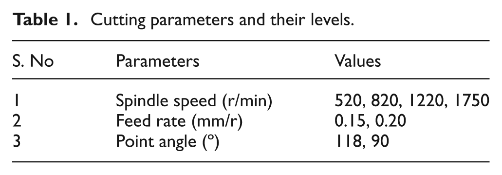
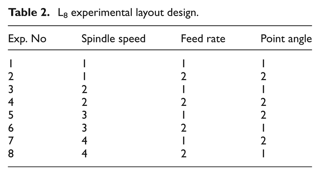
To evaluate the performance of cutting with MQL, drilling tests were carried out in a radial drilling machine. A number of process parameters influenced the quality of the drilled holes. However, it is not easy to take into account all the parameters for improving cutting performance. In this study, three important parameters, spindle speed, feed rate and point angle, of the drill tool that affects the quality of the drilled holes significantly, were considered. The parameter values chosen to conduct the experimental study are given in Table 1. The choice of parameter values were based on recommended standards for the combination of tool work and the ability of the drilling machine used. The levels of the three parameters were different, i.e. mixed level. Four levels for factor cutting speed and two levels for the other two factors, feed rate and point angle, were used. Since the experiments are conducted in dry, wet and MQL conditions, the number of experiments was more. Moreover, replication of experiments were also carried out to substantiate the results. So, L8 orthogonal array (OA) was chosen. MINITAB was used to select the appropriate Taguchi OA. The L8 OA was used to conduct experiments and are shown in Table 2. To substantiate the results as reliable it is usual to replicate the experiments. In this study, the experiments were repeated once and the average was taken. The work material was 6063–T6 aluminum with a dimension of 100×100×12 mm. A two-flute HSS Sandvik Ø12 mm drill was mounted on the drill chuck of 25 mm and is used in this study. The experiments were conducted in dry, wet and MQL cutting conditions. 3000 LT LACTUCA water-soluble oil was used in the wet machining in the proportion of 1:25. UNIST Coolube 2210 was chosen as the fluid in MQL cutting. Figure 1 shows the complete experimental setup consisting of radial drill, MQL setup, coolant nozzle and compressor. An air pressure of 5bar is supplied to the MQL mixing chamber setup. MQL oil was broken into smaller droplets and these droplets were carried to the point of cutting by the high pressure and velocity air. The high velocity oil–air mixture enters the tool-work contact point. The amount of oil–air mixture is maintained at a flow rate of 50ml/min through control valves provided.
Cutting parameters and their levels.
L8 experimental layout design.
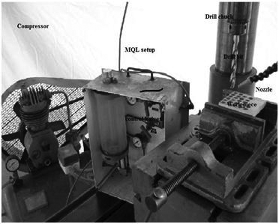
Experimental setup.
To determine the drill tool performance, drilled hole diameter, burr height, taper of drilled hole, chip thickness, tool wear, cutting power and surface roughness were measured. The hole diameter was measured using a Mitutoyo Vernier Caliper (Kawasaki, Japan) at three points and the average was taken. The heights of the burr hole taper were measured using a Mitutoyo dial gauge. The burr height was determined at four points that are separated by 90°. During the measurement of taper greatest effort has been taken in setting workpiece sides at right angles. In addition, the difference in the diameter of the hole in the top and bottom of the hole was also considered during the taper measurement. The average chip thickness is determined from ten sample chips of each experiment. The tool wear was measured after each experiment, with the help of an optical microscope. The cutting power was calculated from the measured voltage and current during the drilling of holes in all cutting conditions. The surface roughness was measured by Mitutoyo SJ-201 Surftest at four points for more consistency.
Artificial neural network prediction model
Artificial neural network (ANN) is extremely successful in very complex problems, such as signal processing, market prediction, speech and pattern recognition, optimization, etc. ANN has successful application in many areas, particularly where the relationship between input and output is not known and where a high degree of uncertainty is present. ANN has fully interconnected multi layers consisting of neurons as the basic element. Each neuron receives a number of inputs, either from the original data or from the output of other neurons in the neural network. Each input comes via a connection that has a weight. These weights correspond to synaptic efficiency in a biological neuron. The neurons, also called nodes, operate in parallel and the connection of weights between the next layers used to store the knowledge.
19
Each neuron also has a single threshold value. The weighted sum of the inputs is formed and the threshold subtracted to compose the activation of the neuron. The activation signal is passed through an activation function, also known as a transfer function, to produce the output of the neuron. This function returns a value on the interval of −1, 1 or alternatively 0, 1. The selection activation function is the ANN designer’s choice. A common activation function is the sigmoidal function

where
The parameter s defines steepness of the sigmoidal function. The mathematical model of this is shown in Figure 2. This process continues and the information passes to adjacent layers up to the output layer to get the desired output. The network must be trained to adjust the weights of each node to minimize the error between the actual and desired output. Since the number of experimental data (input) is less, the weights of the ANN model may not be determined fully and it will reflect in a higher prediction error. But, different ANN topologies and many iterations were analyzed and an appropriate one was determined with acceptable error limits. The most commonly used network training method in an ANN is the back propagation network. In this structure, the steepest decent method was used to adjust the weights with respect to the computed error. 20 To avoid the saturation of the activation function the normalized values are used. If the network is trained by providing inputs and matching output patterns, then it is called a supervised learning technique. Figure 3 depicts the supervised learning paradigm.
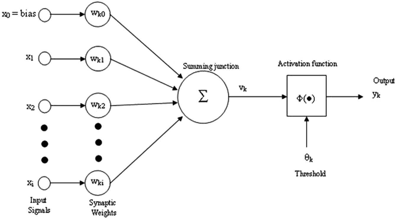
Mathematical model of neuron processes.
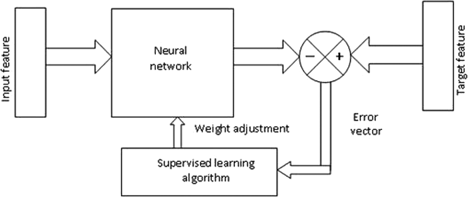
Paradigm of the supervised learning technique.
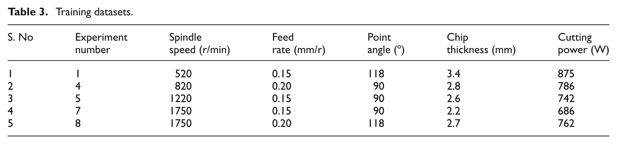
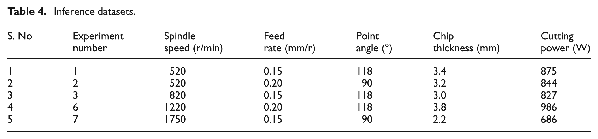
In this study, program C was written with a back propagation algorithm and executed. This program consisted of training and inference stages. A three-layered feed-forward back propagation ANN was designed for training, inference and testing. The spindle speed, feed rate, point angle, chip thickness and cutting power were the five parameters considered for input and the normalized values of these parameters were fed as input to each neuron in input layers. In these inputs, spindle speed, feed rate and point angle are machining parameters and chip thickness and cutting power are experimental results. In this network model, two hidden layers, each with ten neurons, are preferred after brief investigation. Choosing the precise number of neurons in the hidden layer is significant and complex. Too few neurons may lead to a lack of approximation of the desired output function. Too many neurons may lead to overtraining of the network and works on the few test samples but is ineffective for other inputs. The surface roughness and tool wear are the two neurons of the output layer. The proposed architecture of input-hidden output layers is shown in Figure 4. The machining parameters have complicated relationships with quality characteristics. The increase in spindle speed improves the surface quality, but an increase in feed rate will deteriorate it. The point angle also has great impact in hole quality. Since the relationship between the parameters is complex, an ANN is used here to predict the quality characteristics. From the eight MQL experimental results, five datasets are utilized to train the network and are given in Table 3. The remaining three datasets and two from training datasets are used to infer the accuracy of the proposed neural network. Table 4 gives the five datasets utilized for inference.
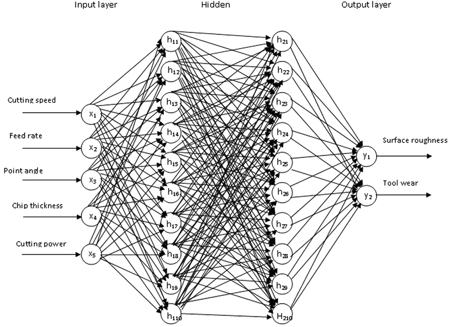
Proposed ANN model.
Training datasets.
Inference datasets.
Results and discussion
The experimental research was conducted to evaluate the different cutting conditions, such as dry, conventional wet and MQL machining. The quality characteristics considered were drilled hole diameter, height of the burr, hole taper, chip thickness, tool wear for drilling, cutting power and surface roughness.
Hole diameter
The drilled hole diameter was measured in all dry, wet and MQL conditions because it is one of the main quality characteristics. The diameter was determined at three points and the average value was considered. The resulting values are given in Figure 5 and it is clear that the diameter of the hole is closer to the diameter of the drilling tool (12 mm) in MQL, than in dry and wet conditions. The maximum hole diameter in dry, wet and MQL is 12.05 mm, 12.04 mm and 12.02 mm, respectively. The deviation of hole dimension in MQL is a smaller amount than dry and wet conditions. The percentage variation of the hole dimension is lesser in MQL than dry and wet machining. The maximum percentage of variation in MQL is 0.17%, whereas it is 0.42% in dry and 0.33% in wet machining. The minimum variation of hole size in MQL is due to less vibration. The effective lubrication at the cutting point reduces friction and thus vibration. Therefore, the variation in hole size is less for all experiments in the MQL condition. The trend line (TL) in Figure 5 illustrates that variation in the diameter of the hole is smaller in MQL cutting than other conditions. The gradient of dry machining TL is slightly increased and far from the required dimensions. The TL in wet machining is a steep decreasing slope with more deviation than dry machining at some points, however, the MQL slope is much lower. Almost all points are near the required dimension and shows that the variation is less, regardless of the cutting speed, feed and point angle.
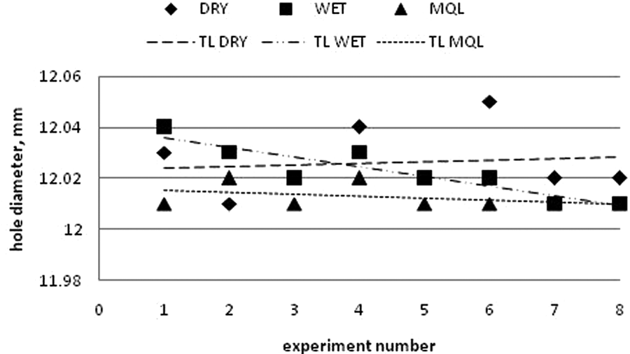
Diameter of drilled holes.
Burr height
Burrs produced around the drilled holes is inevitable. Often, this will affect the function of a product or leads to a secondary operation to remove the burrs. Therefore, control of the burr during drilling is important. The burr height was measured at four points around the holes separated by 90° and the average values were taken. The burr heights varied 0.01–0.09 mm in dry, 0.01–0.13 mm in wet and 0.01–0.03 mm in MQL conditions. The MQL produced burr heights of 1/3 that of dry and 1/4 that of wet machining. The temperature at the chip formation area influences the burr size. At higher temperatures, materials become more deformable and lead to chip formation. In MQL, the high velocity atomized lubricant reaches the cutting point and decreases the temperature at the cutting zone efficiently. This lessens burr formation and improves the machining efficiency. Figure 6 shows the height of burrs in different experiments in dry, wet and MQL conditions. During dry machining, the burr height was lower in many experiments. The TL was almost straight since the heights were high only in a few experiments. In wet machining, burr height grew steadily and steeply and are shown in the TL. The height of the burr and the variation was much lower in MQL machining, and is clearly demonstrated by the TL. From this it is obvious that the MQL results in less burr height compared with all cutting conditions. Dry machining also produced better results than wet machining.
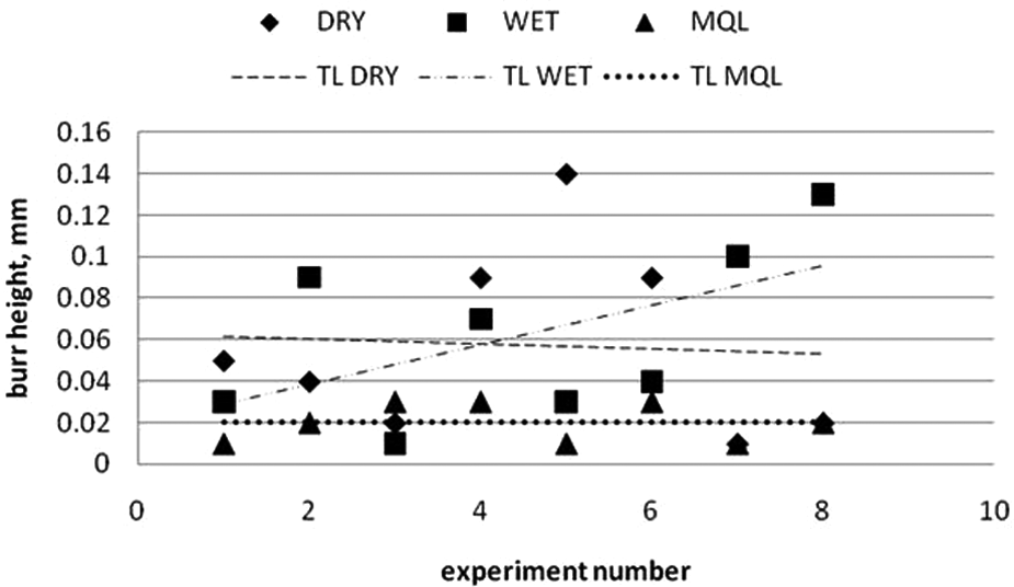
Burr height in different experiments.
Hole taper
The straightness of the hole axis is influenced by many factors, such as vibration, stiffness, tool overhang, cutting conditions, etc. The fixing of the workpiece in the vice is also vital in the production of a straight hole. Therefore, utmost care was taken in the setting of the workpiece. The measured hole taper is given in Figure 7. The experimental results show that, in all cutting conditions, the hole taper was steadily rising. The maximum taper in dry, wet and MQL is 0.11 mm, 0.20 mm and 0.06 mm, respectively. The taper in drilled-hole geometry is more common. This is due to thermal distortion of the drill tool and workpiece and clamping of the workpiece. A large amount of heat should be removed from chip and workpiece during drilling of the hole. The low velocity coolant in wet machining could not reach the cutting zone and splashed away by drill tool rotation. But in MQL, owing to the high velocity lubricant reaching the cutting zone the heat and friction reduces. Therefore, there is less taper geometry error by a lower thermal distortion of tool and workpiece. The wet machining produced a more tapered hole than other cutting conditions. The smallest taper was given by MQL machining. The higher cutting speed and feed rate leads to a greater overhaul.
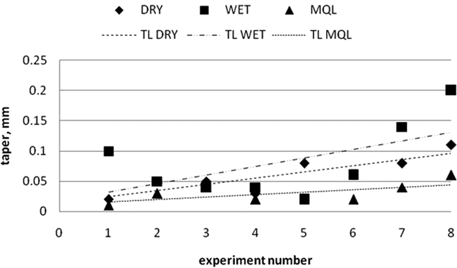
Hole taper in different experiments.
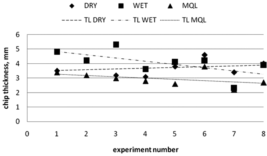
Chip thickness
The cutting edge of the tool penetrates into the workpiece and shears the material ahead of the cutting tool to initiate the formation of the chip. The angle between the direction of velocity and shear plane is called shear angle (Φ). Then the chip is partially deformed and moves along the rake face of the tool. Greater penetration of the tool produces a new machined surface and chip. The thickness of the chip produced depends on the angle of shear. Figure 8 illustrates the relationship between the shear angle and chip thickness. The chip thickness (h2) produced in a high shear angle (Φ2) was lower than the chip thickness (h1) with a low shear angle (Φ1). Figure 9 shows the thickness of the chip produced in dry, wet and MQL. The thickness of the chip produced during MQL was less than the thickness of the chip produced in dry and wet conditions. In a machining process the high shear angle is always an advantage, since the increase in the shear angle reduces cutting forces. The maximum chip thickness produced in MQL is 3.8 mm, but in dry and wet it is 4.6 mm and 4.2 mm, respectively. Therefore, the chip thickness in MQL is 17% lower than dry and 9% lower than wet machining. It is clear from the minimum chip thickness; the MQL provides lubrication at the chip–tool interface and reduces adhesion between chip and tool. Figure 10 shows the chips produced in dry, wet and MQL machining.
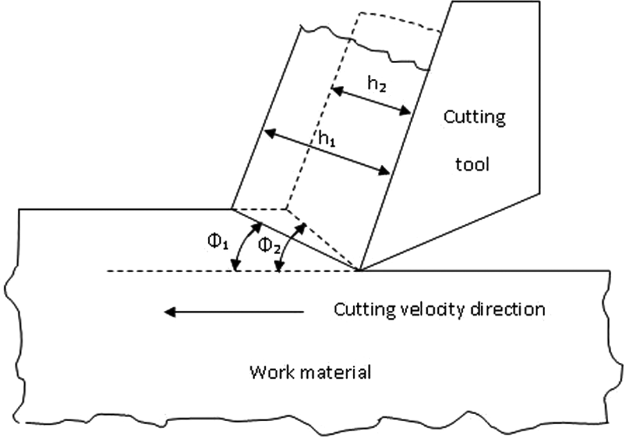
Variation of chip thickness with shear angle.
Chip thickness in different experiments.
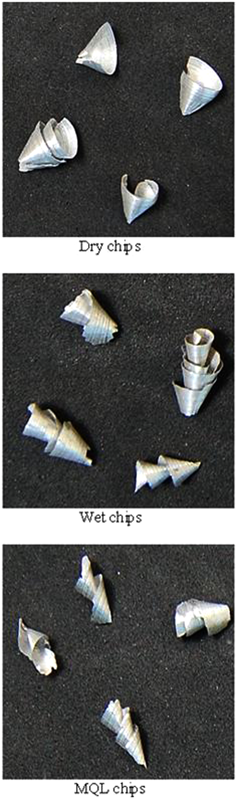
Photograph of chips produced in experiment number 6.
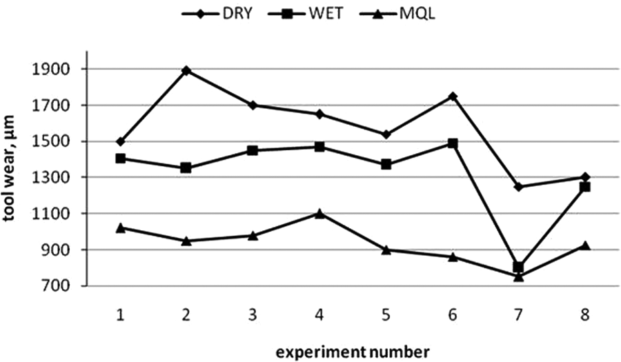
Tool wear
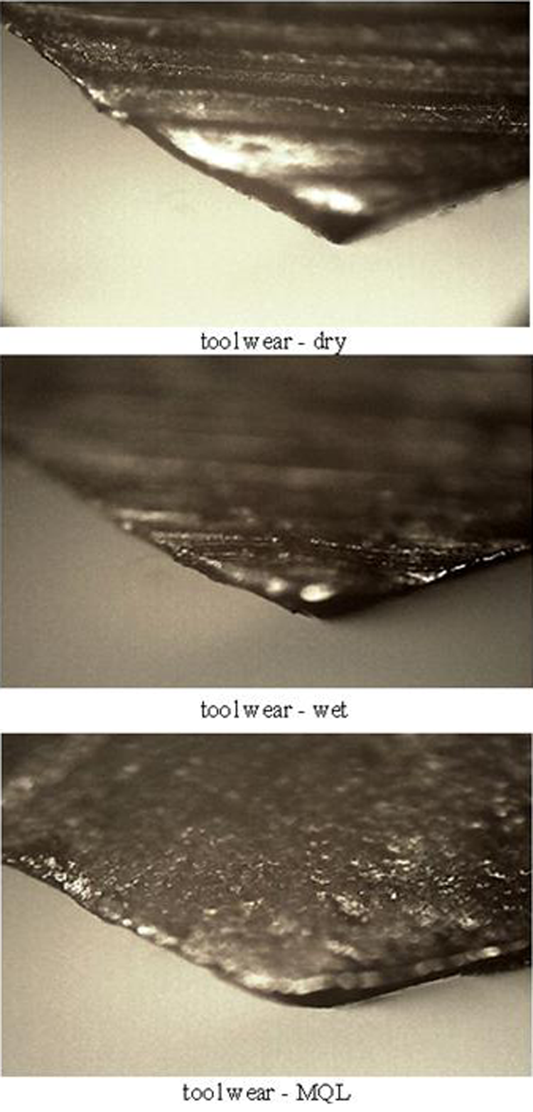
Tool wear is one of the most prominent factors in metal cutting as well as affecting the performance of cut in terms of surface finish, cutting force and dimensional accuracy. Tool wear in dry cutting, wet and MQL is given in Figure 11. For each experiment a new drill tool was used and the measurements of tool wear were taken. It is clear from the results that the MQL produces minimal tool wear by comparing all the conditions of dry and wet machining. Moreover, the MQL also have less deviation of tool wear, regardless of cutting parameters. This ensures the promising application of MQL at all stages of machining parameters. Figure 12 shows the optical microscope images of drilling tool wear in experiment number 2 (cutting speed=520r/min, feed rate=0.20 mm/r, and tip angle=90°) in dry, wet and MQL conditions. The tool wear in dry machining of 1890µm resulted owing to the high temperature and pressure at the cutting point. The cutting point loses its hot hardness, strength and toughness because of the absence of coolant and lubricant to reduce the cutting temperature and friction. In the same cutting conditions the experiment was carried out under wet machining. The tool wear was considerably reduced to 1350µm. This is due to cooling and lubrication provided by the enormous flow of coolant. The tool wear in MQL was 950µm, which was a lot lower than the dry and wet conditions. The maximum tool wear in dry is 1890µm, whereas it is 1490µm and 1100µm in wet and MQL conditions, respectively. This shows that MQL gives lesser tool wear by 71.8% and 35.9%, compared with dry and wet, respectively. The average tool wear is also lower by 68% and 41.4%, compared with dry and wet, respectively. The micro chipping and catastrophic failure present in the wet and dry machining is because of severe thermal stresses owing to longer heat transfer. This shows that there is insufficient cooling during wet machining. However, in MQL machining gradual tool wear is presented. This shows that the MQL provides very effective cooling and removes the heat by supplying lubricant at areas of tool–chip contact, tool–work contact and shear zones. The reduction of heat from the cutting area improves the cutting performance in MQL machining.
Tool wear in different experiments.
Images of tool wear in different cutting conditions.
Cutting power
Cutting power is often an indirect measurement of cutting forces during metal cutting. It is a simple and cost-effective cutting performance analysis. Figure 13 shows the cutting power measured in dry, wet and MQL conditions during drilling. The highest power consumption in dry and wet conditions is 1134W and 1128W, respectively. Even though the wet machining shows higher consumption, both are very close. The MQL consumed only 986W, which is nearly 15% lower than other conditions. The average power consumption in MQL is also lower by 21.2% and 33% than dry and wet machining, respectively. The results show that MQL uses less energy than dry and wet conditions. The energy spent in cutting was higher in wet than dry machining in some experiments, and there was greater variation in cutting power consumption for each experiment in the wet machining. Since cutting energy directly related to the cutting force, is clear from the results that the MQL is capable of providing less cutting force.
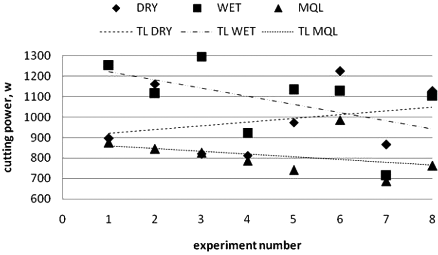
Cutting power in different experiments.
Surface roughness
A good surface quality is one of the main objectives in a machining process as it affects the functional attributes of the product and the manufacturing cost. The results of the surface roughness are shown in Figure 14. MQL improves the surface quality by 31% and 15% compared with dry and wet machining. Since the TL slope is lower for MQL, the variation of surface roughness was also less. Because of better cooling in MQL, the excessive heat was removed from the cutting zone effectively. Also, better lubrication reduces the friction between tool and chip and tool and work leading to less tool wear. This causes better surface quality in MQL machining than the dry and wet machining. In the experimental design four levels of cutting speeds were chosen, whereas only two levels were considered for feed rate and point angle. So, the surface roughness was reduced owing to an increase in cutting speed and shown with the negative slope TL.
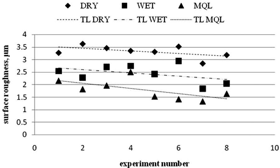
Surface roughness in different experiments.
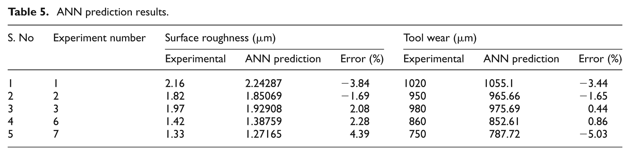
ANN prediction of surface roughness and tool wear
The training and inference datasets are given as input from the experimental results of MQL machining into the C program. The ANN topology information, like number of neurons in input, hidden and output layers and number of hidden layers, is specified during the execution of the program. In addition, the training parameters; momentum factor, learning rate, error constant, scaling factor, number of training data and iteration are also specified. The program window (Figure 15) shows the ANN topology and training parameter values. The developed feed forward ANN with back propagation algorithm predicts the surface roughness and tool wear accurately. The results are given in Table 5. It is observed from the results that, in all the cases of inference datasets, the prediction is quite accurate with the various combinations of input parameters. The maximum deviation in prediction for surface roughness is ±4.4% and for tool wear it is ±5%. Since the errors are within the acceptable level, the developed ANN model is very successful in prediction of quality characteristics of drilled hole.
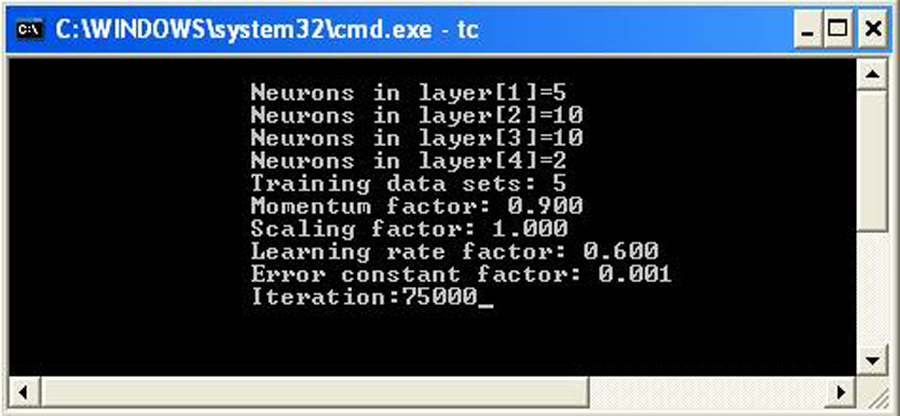
ANN topology and training parameters in the program window.
ANN prediction results.
Conclusion
From the results of drilling experiments conducted in 6063–T6 aluminum on a dry, wet and MQL the following conclusions can be made.
Dimensional deviation of a hole is lower in MQL machining by 60% and 50% than dry and wet machining, respectively. The hole taper is also reduced by nearly 50% in MQL than other conditions.
The burr size in MQL around the drilled hole is 1/3 of that in dry and 1/4 of that in wet machining.
The chip thickness is considerably lower in MQL machining conditions, i.e. 17% and 9% lower than dry and wet conditions, respectively.
Gradual tool wear is presented in MQL, whereas micro chipping and catastrophic failure is present in the dry and wet machining. The maximum tool wear in MQL is 1100µm, which is much lower than dry (1890µm) and wet (1490µm) conditions.
Average cutting power consumption is also less in MQL machining by 21.2% and 33% when compare with dry and wet machining, respectively.
Quality of the surface is improved in MQL by 31% and 15% compared with dry and wet machining, respectively.
The developed ANN back propagation model effectively predicts the surface roughness and tool wear.
This study confirms the improved performance of MQL, and suggests MQL as the best alternative to wet machining to eliminate environmental impacts.
Footnotes
This research work is supported by All India Council for Technical Education, New Dehli, India.