
Abstract
This article describes the multi-response optimization of electrochemical machining operating parameters such as voltage, concentration of the electrolyte, and current to maximize the rate of material removal in addition to minimize the over cut and delamination at the same time in micro-drilling of AA6061-TiB2 in situ composite. A novel Entropy–VIKOR method is applied to handle such mutually conflicting responses. The weight of each response is computed from the entropy method, and VIKOR method is used to rank the various levels of parameters. This method yields the combination of 2 mol of electrolyte concentration, 16 V of applied voltage, and 4 A of current as optimal parameters to minimize the over cut and delamination in addition to maximize the rate of material removal at the same time. This optimal process-governing parameters satisfied the conditions for compromising solution such as acceptable advantage and acceptable stability condition. The response graph illustrates that, of the parameters investigated, electrolyte concentration has the greatest effect on the VIKOR index, followed by applied voltage and current. Scanning electron microscopic analysis illustrates that the radius of the hole is equal throughout the periphery, except for one instance of micro-delamination.
Keywords
Introduction
Composite materials are attracting attention within the aerospace, automotive, and space sectors due to their enhanced mechanical properties at room and elevated temperatures, weight-saving potential, superior corrosion resistance, and tailorability. 1 Aluminium composites have great potential for use in liners, pistons, brake drums, and rotor discs in automobiles; compressors and turbine blades in aerospace industries; and packaging and thermal-conductivity-controlling materials in the electronics industry. 2 The real-time application of engineering components requires much strength, wear resistance, a high Young’s modulus, and tremendous dimensional stability. 3 Large reinforcement particles, dirty reinforcements, oxide contamination during preheating, and poor distribution of reinforcements are notable drawbacks of composites that are fabricated by ex situ methods. 4 These drawbacks are considered major sources of degradation of the mechanical properties and restrict the extensive application of composites. In situ reinforcement formation via flex-assisted synthesis is becoming more popular as an uncomplicated and inexpensive alternative method for manufacturing aluminium-based composites. 5 Aluminium-based in situ composites have numerous benefits, such as having particulates with good thermodynamic stability, a clean matrix–particulate interface, greater interfacial bonding between the matrix and particulates, and cluster-free reinforcement particulates as a consequence of the formation of very fresh, fine, dust-free, and oxide-free ceramic particulates. 6 Therefore, the flex-assisted synthesis method of manufacturing in situ composites is an efficient way to overcome the aforesaid challenges.
AA6061 is a 6xxx series (Al-Si-Mg) alloy and possesses moderate strength as a result of the incorporation of Mg2Si. It is extensively used in the construction of ships and other lightweight structures.7–9 TiB2 is a popular ultra-high temperature ceramic phase and has fabulous mechanical and physical properties. TiB2 has excellent chemical stability, great hardness, a high melting point, superior wear resistance, relatively low density, and excellent electrical and thermal conductivity. 10
Not long ago, the synthesis of aluminium composites reinforced with TiB2 using K2TiF6-KBF4-aluminium melt reactions and the evaluation of mechanical properties under various treating conditions received the attention of researchers worldwide.11–13 AA6061-TiB2 composites have several beneficial effects. For example, the TiB2 particulates act as a diverse nucleation region and facilitate the fine grain size of aluminium. Also, the TiB2 particulates at the inter-dendritic zone obstruct the growth of Si and enable a fine microstructure. Furthermore, the TiB2 particulates refine the coarse Mg2Si and hinder its negative effects.14,15 Mandal et al. 16 described a suitable reaction time and temperature for avoiding the formation of an Al3Ti phase. Liu et al. 17 emphasized the stirring of an aluminium melt after the completion of the exothermic reaction. This stirring action helps to break the TiB2 particle cluster, thereby achieving a homogeneous particle distribution.
Manufacturing components with intricate profiles and low surface roughness using a hard-to-cut material is still a challenge. 18 The conventional machining process has countless limitations. Some of the most notable of these are related to macro-level material removal rate (MRR), tool wear rate, and material hardness. These limitations make it challenging to convert the material into the desired shape. 19 Electrochemical machining (ECM) enables micro-level material removal without needing to consider the hardness of the material to be machined. In ECM, the material machining process is carried out based on Ohm’s and Faraday’s laws. However, there is no physical contact between the tool and the workpiece during ECM. 20 The electrochemical dissolution effect brings many advantages (e.g. a faster rate of machining of materials irrespective of their hardness, a residual stress-free machined surface, the absence of a heat-affected zone on the machined surface, the elimination of tool wear, a desirable surface finish, and good dimension control and accuracy). 21 ECM is widely used in industries to form cavities in forged die; to make intricate profiles, such as turbine wheels, turbine jet blades, and thin-walled components; and to drill holes with large aspect ratios and complicated shapes.22,23
Today’s industry scenario requires a greater production rate, enhanced quality of products, a decrease in production costs, and a curtailing of environmental impacts. Controlling delamination and radial overcutting in ECM are tedious tasks. The delamination factor is determined by the ratio of the maximum diameter (Dmax) of the delamination zone to the hole diameter (D). Figure 1 illustrates the delamination of the drilled hole. Radial overcut is defined as half the difference between the diameter of the hole produced and the tool diameter. The optimization of machining parameters is intended to achieve the aforesaid manufacturing necessities. Alternatively, manufacturers may rely upon trial and error or the ability of the operator, neither of which results in optimum operational parameters. 24
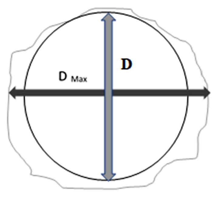
Delamination of the hole.
However, it is very difficult to combine all aspects of production challenges within a single response. The real-time operations associated with multiple responses are used to achieve the manufacturing goal. Multiple response optimization provides reasonable correlations among heterogeneous responses and helps to attain the solo optimum setting of process parameters that meets the specifications of all responses. 25 Biswesh et al. 26 proposed an response surface methodology (RSM)-based nondominated sorted genetic algorithm to optimize the electrochemical machine operating parameters to increase the rate of material removal and reduce the roughness of the machined surface during the machining of hardened steel. A Pareto optimal solution was obtained by uniting the current, voltage, and flow rate of electrolyte and inter-electrode gap, thus providing a simultaneous reduction of surface roughness and a greater rate of material removal. It is also noted that the multi-response optimization method yields superior performance for the two conflicting responses. Mehrvar et al. 27 utilized an algorithm based on response surface methodology coupled with differential evolution and obtained an optimal solution for the ECM of stainless steel. The single response optimization illustrates that a greater rate of material removal was attained at higher voltages, electrolyte concentrations, and tool feed rates, whereas lower surface roughness was achieved at low to medium-low ranges of voltage and electrolyte concentration. However, the proposed multi-response optimization method yields a Pareto optimal solution by considering both conflicting responses. Similarly, many multi-response optimization methods (e.g. quality loss function 28 and grey relational analysis 29 ) have been shown to optimize the electrochemical process parameters for machining various materials.
There is very little literature that deals with the application of the multi-response optimization of ECM parameters for aluminium-based composites. Senthilkumar et al. 30 developed a nondominated sorting genetic algorithm to optimize the concentration of electrolytes, the flow rate of electrolytes, and the voltage and rate of feed of the tool to simultaneously attain a greater rate of material removal and the lowest possible amount of surface roughness in the machining of Al-SiC composites. The sorting practice allows a fitness assignment scheme that chooses the nondominated solutions and uses a sharing strategy that extracts diversity among the solutions. Their analysis revealed that the group response values obtained from the proposed method are in agreement with the experimental values under the same set of parameters. Rao and Padmanabhan 31 proposed a multi-response optimization method by using response surface methodology to discover the optimal process parameter combination for reducing surface roughness and overcutting. They developed a mathematical model by considering the content of the reinforcement, rate of feed, concentration of electrolytes, roughness of the surface, and voltage. The developed model results in minimal surface roughness and overcutting. Ayyappan et al. 32 developed an integrated fuzzy artificial bee colony algorithm to optimize the operating parameters during the ECM of AA6061-Al2O3/SiC composites to attain improved responses for the rate of material removal, roughness of the surface, and overcutting. Their study illustrates that the exactness of the proposed method relies on the accurate modelling of the fuzzy inference system and the steadiness of the artificial bee colony algorithm’s convergence.
The VIKOR method was invented by Opricovic to resolve multiple-criteria choice-making problems involving conflicting criteria by considering compromise as tolerable. The solution is based on the ‘maximum group utility’ for the majority and ‘minimum of an individual regret’ for the opponent. This method appraises a VIKOR index based on its ‘closeness’ to the ‘ideal’ solution. Furthermore, this method offers both a feasible solution, a close to ideal solution, and a far to the worst one. 33 The Entropy–VIKOR method has played a vital role in solving multi-criteria choice-making problems in a variety of engineering applications. With this method, the weight of the criterion obtained from the entropy method is integrated with the VIKOR steps. Sharma et al. 34 intended to optimize the performance-governing parameters of discrete V obstacles in a solar air channel to maximize heat transfer and minimize pressure losses by using the Entropy–VIKOR method. They noted that the optimized process-governing parameters obtained from this proposed method provide the best feasible solution by considering all the responses together. Ismail et al. 35 applied the Entropy–VIKOR method to optimize the drilling parameters along with the reinforcement ratio to reduce the roughness of the drilled hole and minimize the delamination and rate of material removal at the same time during the drilling of A356-TiB2/TiC composites. The confirmation result illustrates that the regression equation developed from the VIKOR index was in good agreement with the experimental values of the identical run.
After a thorough review of the existing literature, it is noted that there is little work on the ECM of AA6061-TiB2 composites produced by K2TiF6-KBF4-aluminium melt reactions. This gap in the literature is filled by the current work, in which the ECM of AA6061-TiB2 composites and the identification of optimal machining conditions are carried out by a novel multi-criteria decision-making method. Hence, an effort has been made to optimize the parameters that govern the ECM process (i.e. current, voltage, and electrolyte concentration) to reduce overcutting, minimize delamination, and maximize the rate of material removal using the Entropy–VIKOR method in the machining of AA6061-TiB2 in situ composites.
Experimental work
The AA6061 alloy was selected as the matrix material. A flex-assisted synthesis method was used to generate the TiB2 ceramic phase by reacting K2TiF6 and KBF4 halide salts with an aluminium melt. The synthesis and characterization of the AA6061-TiB2 in situ composite are described in our previous work. 36 The fabricated composite was made into a 0.5-mm sheet and used for the experimental work. An ECM setup (Sona College of Technology, Salem, India) was followed. The schematic view of the machining setup is exemplified in Figure 2. The machining setup composed of the machining unit and the system for tool feed, electrode gap, pulsed power control, and electrolyte supply. The machining unit includes the main body, the arrangement for tool feed, and a fixture for holding the workpiece. The pulsed control system comprises a pulsed power supply of 20 V and 30 A, with the arrangement for changing the voltage, current, and pulse duration as needed. The duty cycle for the current work is fixed at 65%, and the frequency of the pulsed control system is maintained at 50 Hz. Furthermore, the component of the electrolyte supply system includes the pump and filter. The flow rate of the electrolyte is controlled by the pump. The role of the filter is to remove the debris brought out from the machining and the side product coming out from the electrolysis process. The initial gap between the tool and workpiece is maintained at 50 µm. The tool feed system has the provisions for the tool to be moved along the Z-axis with a 2-µm resolution. A stepper motor interfaced with the 8051 microcontroller controls the electrode gap through the current sensor. This sensor monitors the gap current inside the closed loop and delivers the feedback to the microcontroller. The tool feed control system is crucial to maintaining the machining performance. If the tool contacts the workpiece, a short circuit occurs. This short circuit leads to an increase in the current and damages the semiconductor device. Furthermore, the short circuit induces an unwanted temperature increase and burns the workpiece, thus reducing the efficiency of the machining process and diluting the quality of the machined surface.
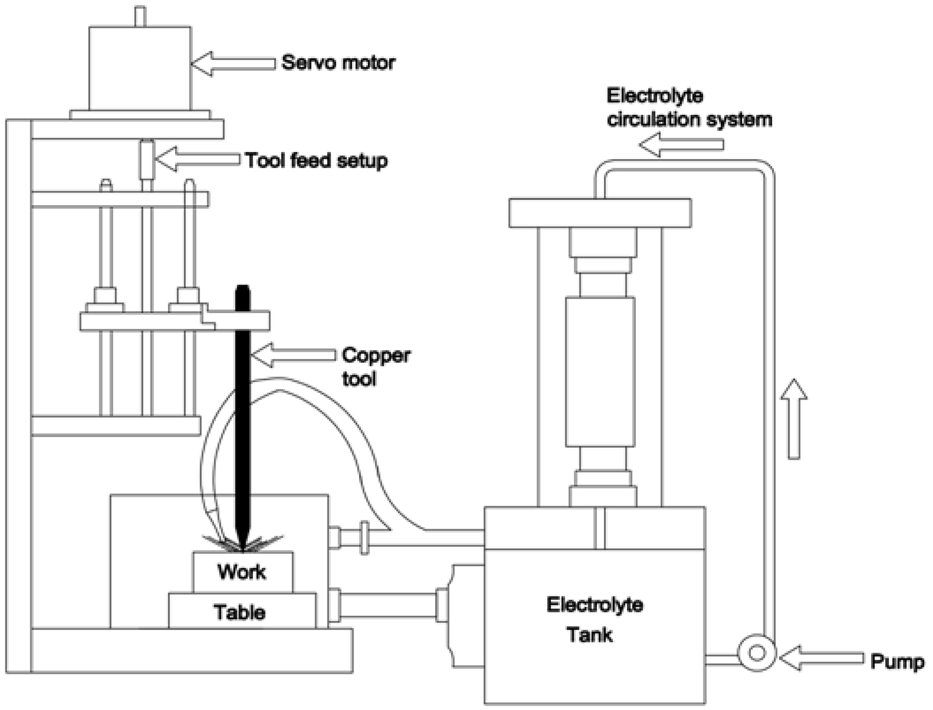
Schematic view of the experimental setup.
Electrolyte concentration, voltage, and current were chosen as machining parameters, whereas the rate of material removal, overcutting, and delamination were chosen as machining responses. A 500-µm cylindrical copper tool was selected, and a NaNO3 electrolyte was chosen for the experimental work. The flow rate of electrolytes is maintained at 10 L/min for the machining work. The rate of material removal was calculated as the ratio of mass loss and the time taken for machining. Delamination and overcutting of the machined hole were measured using a metallurgical microscope. L27 experimental layout is followed for the experimental work. Machining response values are evaluated based on various parameters as reported in Table 1.
Design of experiments and measured responses.
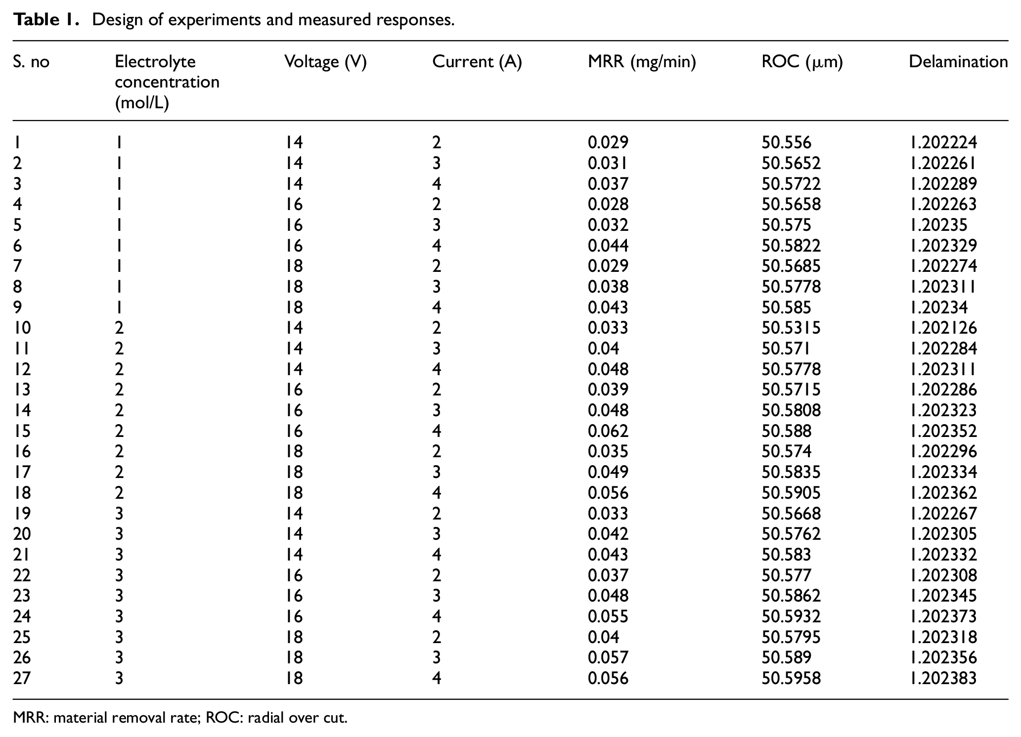
MRR: material removal rate; ROC: radial over cut.
Entropy–VIKOR method
In the Entropy–VIKOR method, the weights of criteria from the entropy method are united with the steps of the VIKOR method. The various steps associated with the Entropy–VIKOR method are described below.
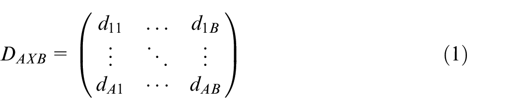
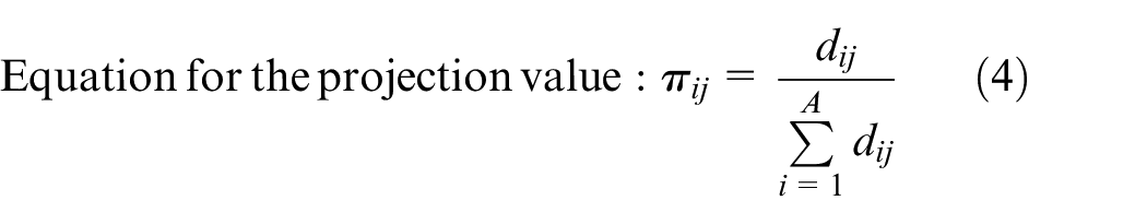
where dij (i = 1, 2, 3, …, A; j = 1, 2, …, B), which denotes the real value of the ith alternative and jth criterion.


where
if j is the benefit criteria for j = 1, 2, 3, …, A.
if j is the cost criteria
for j = 1, 2, …, B.
Where
Results and discussion
Each alternative (A-1 to A-27) comprises an electrolyte concentration, voltage, and current, whereas the rate of material removal, overcutting, and delamination are response criteria. The rate of material removal is a benefit criterion and is to be maximized, whereas overcutting and delamination belong to cost criteria, which are to be minimized. The results attained using different sets of alternatives are optimized using the Entropy–VIKOR method through the following steps.
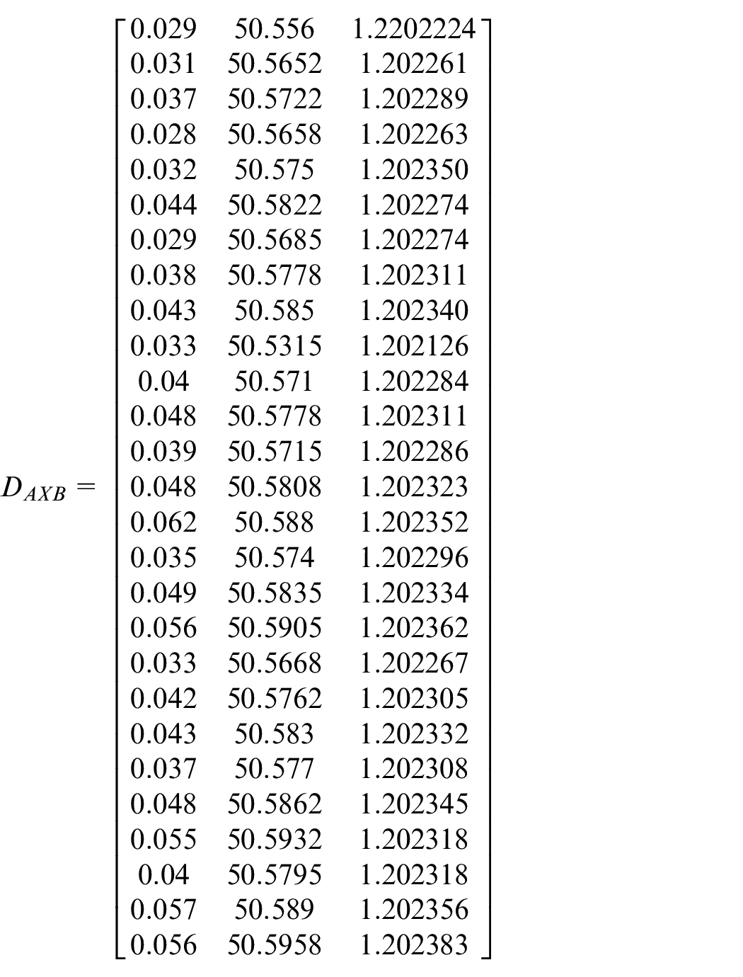
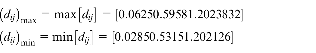
The benefit criterion and cost criterion are identified from the decision matrix as per equations (2) and (3)
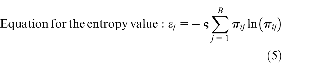
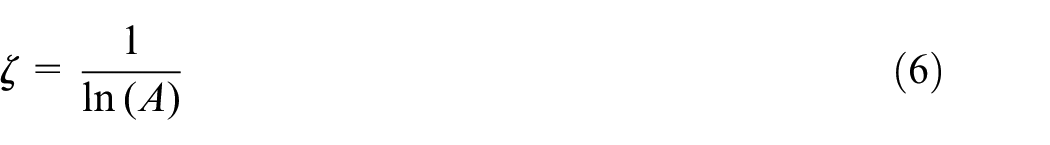
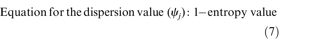
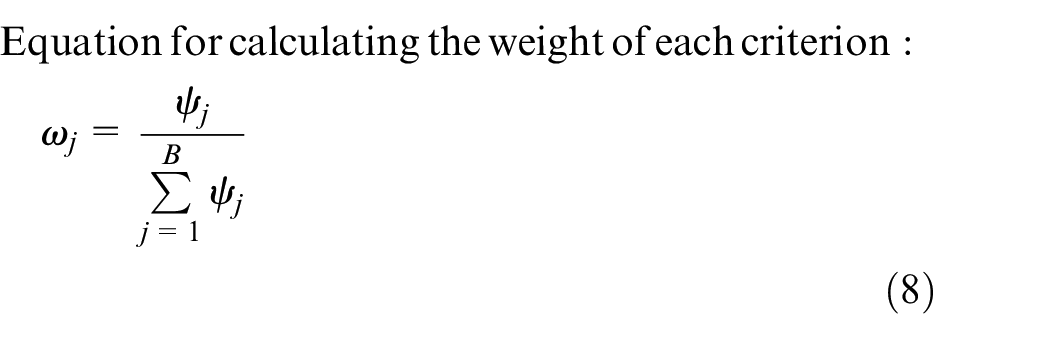
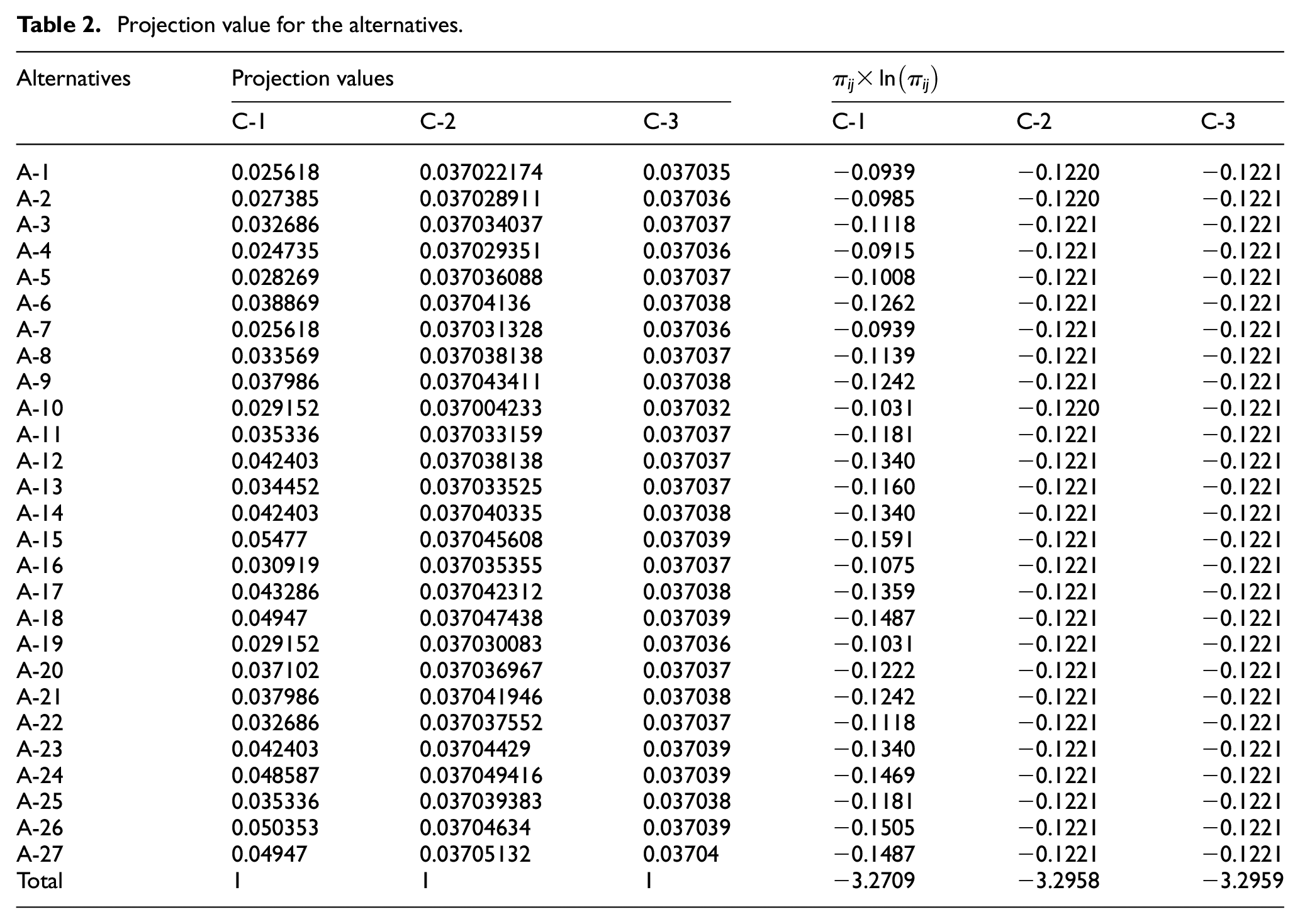
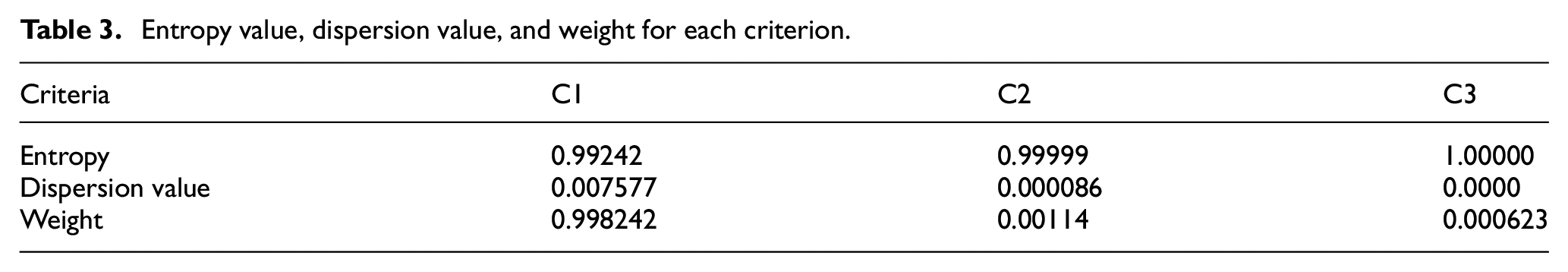
The estimation of the weight of each criterion comprises estimations of the projection value, entropy value, and dispersion value. The projection values for all alternatives are computed using equation (4). The calculated values are presented in Table 2. The entropy value, dispersion value, and weight for each criterion are calculated using equations (5)–(8). These values are exhibited in Table 3.
Projection value for the alternatives.
Entropy value, dispersion value, and weight for each criterion.
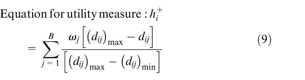
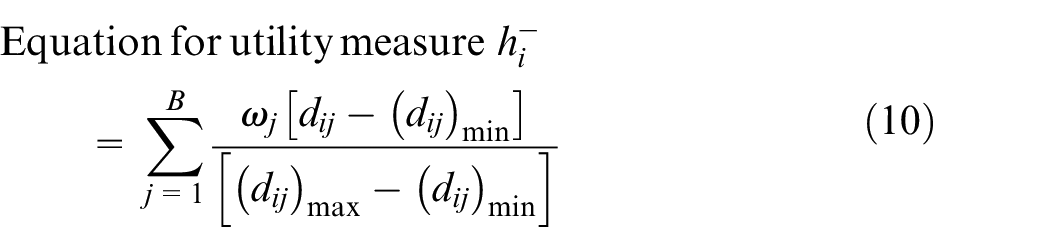
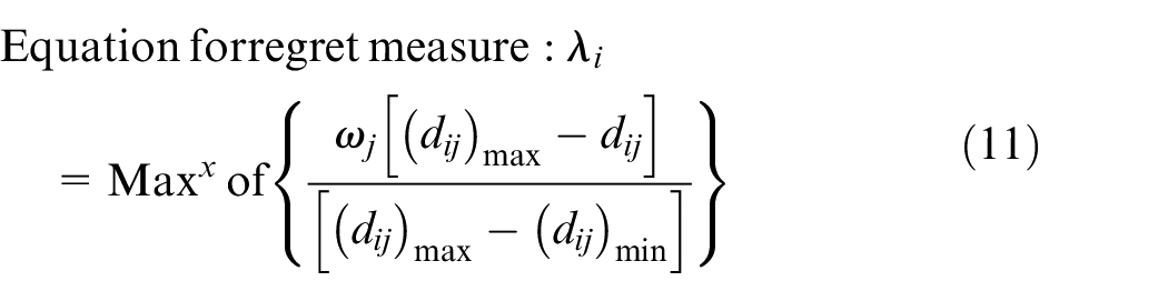
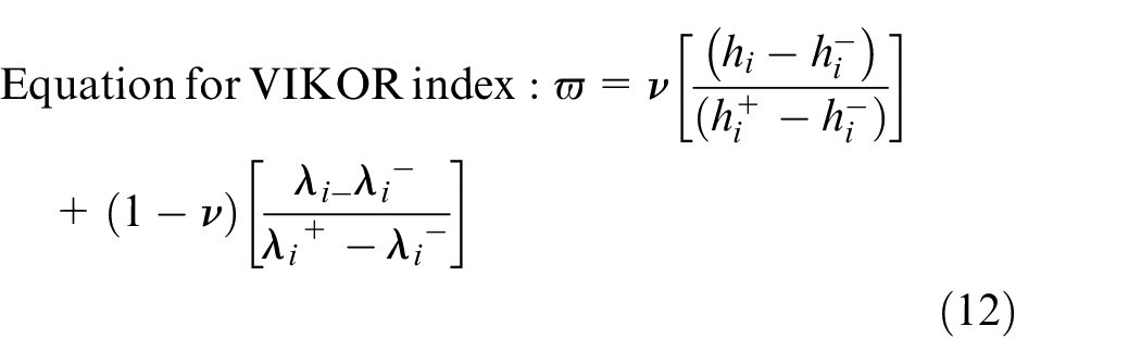
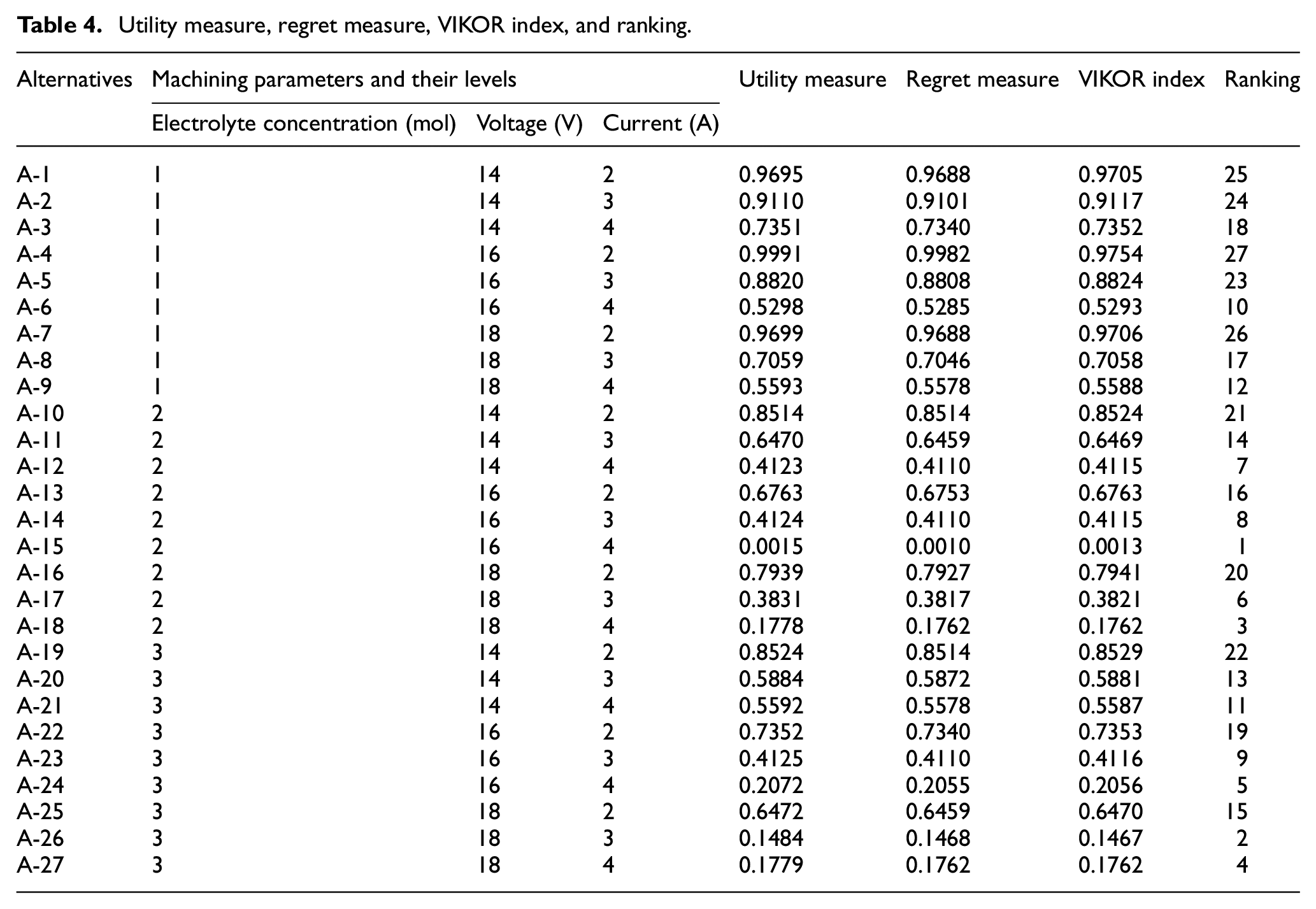
The utility measure for the rate of material removal is calculated using equation (9), whereas overcutting and delamination are computed using equation (10). Furthermore, the regret measure is estimated using equation (11). The VIKOR index is calculated by inserting the utility and regret measure values into equation (12) (see Table 4). The weight of the utility measure component is
Utility measure, regret measure, VIKOR index, and ranking.
Shemshadi et al. 37 and Musani and Jemain 38 described the following conditions to check whether the best alternative yields the compromise solution:
where DQ is denoted as a threshold value and is calculated as
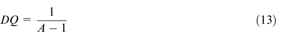
The VIKOR index value for the second-best-ranked alternative is 0.1467, whereas this value for the best-ranked alternative is 0.0013. The threshold value of DQ is
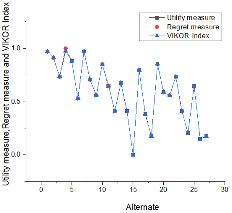
Comparison of utility measure, regret measure and VIKOR index.
The Entropy–VIKOR method integrates all responses to yield a single response. The optimized level of parameters yields greater machining efficiency. Figure 4 illustrates comparisons of the rate of material removal and radial overcutting for various alternatives. Alternative A-15 is associated with the greatest rate of material removal. The levels of machining parameters that correspond to the A-15 alternative are 2 mol of electrolyte concentration, 16 V of applied voltage, and 4 A of current. Furthermore, the A-10 alternative has the lowest radial overcut and the lowest amount of delamination. The corresponding levels of machining parameters are 2 mol of electrolyte concentration, 14 V of applied voltage, and 2 A of current. According to single response optimization, a greater value of current leads to a greater MRR. Furthermore, the low current of alternative A-10 reduced delamination and radial overcutting. The single response optimization focuses on only one response at a time, whereas the multi-response optimization deals with several responses simultaneously and converts them into a single response. Figure 5 depicts that the VIKOR index values for the A-15 alternative are lower than the values for all other alternatives. The parameter levels for alternative A-15 is 2 mol of electrolyte concentration, 16 V of applied voltage, and 4 A of current. ECM is a micromachining process in which increasing the current accelerates the rate of material removal. The moderate levels of electrolyte concentration and voltage associated with the A-10 alternative control delamination and radial overcutting.
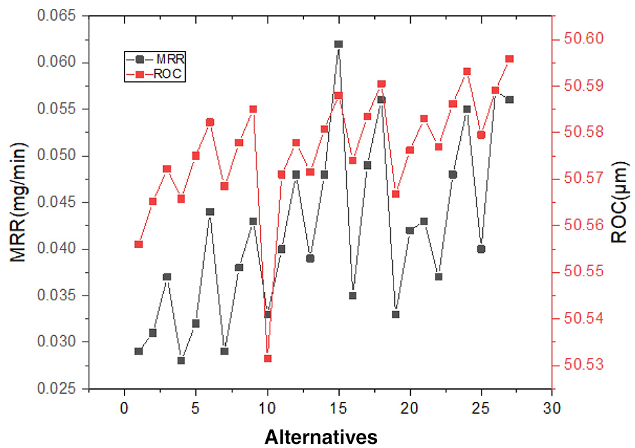
Comparison of MRR and ROC at different alternates.
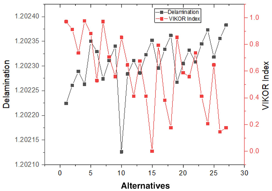
Comparison of delamination and VIKOR index at different alternates.
The applied voltage provides the DC current flow between the electrodes and facilitates the anodic dissolution process. Nevertheless, the reaction at the cathode terminal will be the hydrogen gas generation. Furthermore, the applied voltage charges the electrode surface, and this surface attracts the dipoles and oppositely charged ions from the electrolyte. This effect forms the electrical double layer. There is a drawback to applying constant potential. The workpiece attains a strong level of polarization from the tool and initiates the dissolution process. Over time, the rate of material dissolution is maximized because of the electrical double layer. Greater dissolution due to constant potential maximizes overcutting and the size of the deviation of the top- and bottom-hole during drilling.
The Entropy–VIKOR method reveals that 16 V is the optimal voltage for improving the overall machining process; 16 V is a moderate level of voltage within the selected range and provides the necessary DC current flow to attain a sufficient level of anodic dissolution without dissipating more heat at the machining interface. As a result, overcutting declines, as does the deviation between the diameters of the top and bottom holes. Furthermore, the pulsed power supply system was applied with 20 V and 30 A, with the voltage, current, and pulse duration changed as needed. The duty cycle for the power supply is fixed at 65%, and the frequency of the pulsed control system is maintained at 50 Hz. This power control system restricts the duration of the power supply and minimizes the current density at the machining interface. This could be an additional cause of the minimal overcutting and delamination of the drilled hole.
The utilization of sodium nitrate electrolytes prevents stray corrosion and offers a close duplication of the tool shape. It is also advantageous for maintaining the cylindricity throughout the hole. The Entropy–VIKOR method reveals that a 2-mol electrolyte concentration offers the best overall machining performance. According to Wang et al., 39 a greater concentration of electrolytes distributes the current at a higher density due to its extreme electrical conductivity and the resulting availability of more ions for reactions. This mechanism maximizes the machining rate, overcutting, and delamination. A lower concentration of electrolytes has more electrolyte resistance and reduces the rate of material removal. 40 The pulsed power supply further decreases the rate of material removal. However, a low electrolyte concentration improves the machining resolution, thereby reducing overcutting and delamination. Thus, the 2-mol electrolyte concentration with a pulsed power supply system yields an admirable rate of material removal without diminishing the cylindricity of the drilled hole.
The Entropy–VIKOR method reveals that 4 A is the optimal level of current for attaining the greatest rate of material removal while also minimizing delamination. It is a greater value within the selected levels of parameters. Generally, a greater value of current than the selected values may be preferred for surface machining. In the case of drilling, a greater current dilutes the cylindricity of the drilled hole via overcutting and delamination. Joule’s first law states that the heat produced at the machining interface is directly proportional to the square of the current, time of the current supply, and electrical resistance. A greater current maximizes the temperature of the electrolytes, thereby raising their conductivity. This effect maximizes the rate of dissolution and facilitates faster machining under a constant supply of voltage. However, it is not advantageous for drilling processes in which hole cylindricity is essential. Hence, the 4-A current supply with a pulsed power supply offers a desirable resolution while controlling overcutting and delamination. Rathod et al. 41 state that a high current and low voltage are preferred for obtaining a high rate of machining. However, a voltage of 16 V and a current of 4 A with a pulsed power supply has a greater influence on overcutting and delamination, thus retaining the cylindricity of the drilled hole.
A response graph is generated to assess the relationship between the process-governing parameters and the VIKOR index (Figure 6). The VIKOR index diminishes as the levels of electrolyte concentration, applied voltage, and current are increased. Figure 6 also depicts that current has the greatest effect on the VIKOR index, followed by electrolyte concentration and applied voltage.
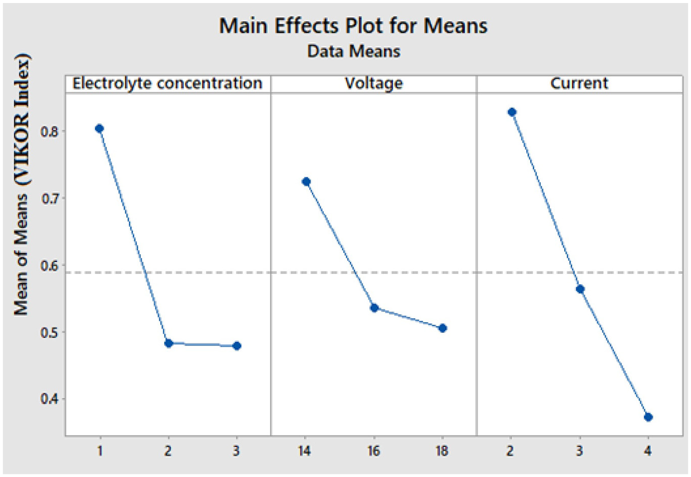
Response graph for VIKOR index.
Figure 7 illustrates the scanning electron microscopic view of a hole machined at 2 mol of electrolyte concentration, 16 V of applied voltage, and 4 A of current. Figure 7(a) shows that the radius of the hole is equal throughout the periphery except for one instance of micro-delamination. Furthermore, the edge of the hole has nano-level erosion due to the lack of insulation around the tool. Figure 7(b) exhibits the interior view of the drilled hole. Some uneven dissolution of the surface and electrochemical debris deposition around the hole can be observed. The reason for the uneven dissolution might be the discontinuous machining, which is caused by the pulsed power supply. However, the pulsed power supply controls dissolution and maintains parameters related to hole cylindricity, such as overcutting and delamination.
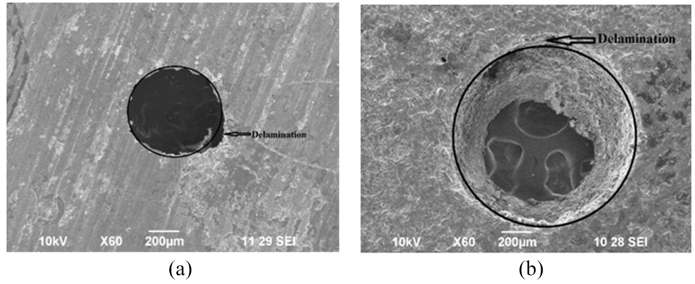
Scanning electron microscopic analysis of drilled holes: (a) External view of the hole and (b) interior view of the hole.
Conclusion
Some ECM operating parameters (i.e. voltage, electrolyte concentration, and current) are optimized to maximize the rate of material removal while minimizing overcutting and delamination during the micro-drilling of an AA6061-TiB2 in situ composite. The optimal levels of parameters that govern the ECM process are identified using the Entropy–VIKOR method. The combination of 2 mol of electrolyte concentration, 16 V of applied voltage, and 4 A of current are optimal for minimizing overcutting and delamination while maximizing the MRR. These optimal parameters satisfied the conditions for a compromise solution, such as an acceptable advantage and acceptable stability conditions. A pulsed power supply system has a significant influence on overcutting and delamination, and the use of such a power supply system retains the cylindricity of an electrochemically drilled hole.
The Entropy–VIKOR method used in the present study handles conflicting responses efficiently. This method simplifies multiple complex responses into a single response in the form of a VIKOR index. The response graph illustrates that, of the parameters investigated, electrolyte concentration has the greatest effect on the VIKOR index, followed by applied voltage and current. The Entropy–VIKOR method is an effective method for optimizing problems related to the ECM process. The operator can choose the specified combinations of machining parameters based on the importance of the process responses. A scanning electron microscopic analysis illustrates that the radius of the hole is equal throughout the periphery, except for one instance of micro-delamination.
Footnotes
Appendix 1
Declaration of conflicting interests
The author(s) declared no potential conflicts of interest with respect to the research, authorship, and/or publication of this article.
Funding
The author(s) received no financial support for the research, authorship, and/or publication of this article.