
Abstract
Laser-assisted micromilling is a promising micromachining process for difficult-to-cut materials. Laser-assisted micromilling uses a laser to thermally soften the workpiece in front of the cutting tool, thereby lowering the cutting forces, improving the dimensional accuracy, and reducing the tool wear. Thermal softening, however, causes the workpiece material to adhere to the tool and form a built-up edge. To mitigate this problem and to enhance micromachinability of the workpiece in laser-assisted micromilling, this article investigates the following lubrication and cooling methods: (1) minimum quantity lubrication and (2) vortex tube cooling. Experiments utilizing the two methods are carried out on a difficult-to-cut stainless steel (A286), and the surface morphology, tool condition, burr formation, groove dimensional accuracy, surface finish, and cutting forces are analyzed. Results show that the combination of laser-assisted micromilling and minimum quantity lubrication yields the least amount of tool wear, lower resultant force, better groove dimensional accuracy, and no built-up edge. While vortex tube cooling with laser-assisted micromilling produces smaller burrs compared to minimum quantity lubrication, it yields larger changes in groove dimensions and is characterized by built-up edge formation. Possible physical explanations for the experimental observations are given.
Keywords
Introduction
As applications in medical and electronics industries continue to drive part miniaturization, cost-efficient manufacturing processes capable of creating microscale features are necessary. For part features of moderate geometric complexity and relatively low aspect ratios, micromilling is a practical option because of its high material removal rates and affordability. However, machinability and tool life in micromilling of difficult-to-cut metals such as stainless steels and titanium- and nickel-based alloys remain a challenge. Hybrid processes1,2 such as laser-assisted micromilling (LAMM)3–6 have been shown to enhance the machinability of such materials. However, unlike conventional machining, where cutting fluids are used to enhance micromachinability and tool life, the use of traditional cutting fluids in LAMM is difficult because they occlude the laser beam and inhibit thermal softening. Consequently, less intrusive micromachinability and tool life enhancement methods are needed for LAMM.
Minimum quantity lubrication (MQL)7–9 and vortex tube cooling10–14 are two machinability and tool life enhancement methods that are potentially suitable for LAMM. However, while there have been many studies of MQL in micromilling,15–21 and limited investigations of vortex tube cooling 13 and blown air cooling 22 in micromilling, there have been no studies of the combined effects of laser heating and cooling or laser heating and lubrication on micromachinability in LAMM. Wang et al. 23 combined plasma-enhanced machining (PEM) and cryogenic cooling to thermally soften the workpiece and to cool the tool, respectively, in conventional scale turning of Inconel 718. Tool life in the combined process was found to increase significantly in comparison to using PEM alone. Pereira et al. 24 investigated machinability enhancement in turning of AISI 304 stainless steel by combining cryogenic cooling and MQL. They found that the combination of cryogenic cooling using either liquid nitrogen or carbon dioxide and MQL yielded the greatest improvement in tool life compared to using any of the cooling or lubrication methods individually. Using the combined cryogenic cooling and MQL approach, Pereira et al. 25 also reported significant improvements in tool life in conventional milling of Inconel 718. In related work, Pereira et al. 26 analyzed the performance of several vegetable and recycled oils as MQL cutting fluids in conventional milling of Inconel 718. They showed that high oleic sunflower oil and recycled ECO-350 oils were environmentally sustainable alternates to commonly used canola oils in MQL applications.
Recent work by Ucun et al. 27 investigated the role of cryogenic precooling and MQL on machinability in micromilling of Inconel 718. They found that cryogenic precooling increased tool wear while MQL yielded better tool life but mixed results for surface finish and burr formation. The use of liquefied carbon dioxide as a cryogenic medium for cooling has also been investigated. Specifically, the combination of carbon dioxide and air cooling using a commercially available multichannel delivery system was shown to reduce flank wear, lower the cutting edge temperature, and increase the material removal rate when cutting a high-strength high-temperature stainless steel. 28 Hybrid cooling and lubrication systems that combine carbon dioxide-based cryogenic cooling with MQL have also been reported for machining of difficult-to-cut materials. 29
While the literature on laser-assisted machining (LAM) of difficult-to-cut materials is vast (see Sun et al. 30 for an exhaustive review), work on machinability enhancement in LAM through cooling and/or lubrication strategies, either at the conventional scale or microscale, is very limited. In conventional scale turning of Ti-6Al-4V, Dandekar et al. 31 combined laser heating with cryogenic cooling and found that tool life increased significantly compared to laser heating alone. Bermingham et al. 32 found that the use of laser heating in conventional milling of Ti-6Al-4V was detrimental to tool life compared to its performance in dry milling. Laser heating tended to increase adhesion and built-up edge (BUE) leading to accelerated notch wear. On the contrary, by combining laser heating with MQL, tool life was greatly improved. However, MQL alone was found to be just as effective as the combined process.
It is clear from the literature review that there is very limited work on cooling and/or lubrication strategies to enhance micromachinability in LAMM. This article presents the results of an experimental investigation of the effects of MQL and vortex tube cooling on micromachinability in LAMM of a difficult-to-cut precipitation hardened high nickel content stainless steel (A286), which is widely used in the aerospace industry for multiple high-temperature applications, including turbine wheels and fasteners. 33 Currently, industry utilizes nontraditional machining processes such as electrical discharge machining (EDM) to produce small-scale features in A286 steel material. However, industry is interested in higher material removal rate processes for these applications, which motivates this work. Specifically, the effects of MQL and vortex tube cooling on various aspects of micromachinability of A286 steel such as the machined surface condition, tool condition including wear and BUE, dimensional accuracy of the groove, surface finish, and cutting forces are evaluated in this article. Specifically, the performance of LAMM + MQL and LAMM + Vortex tube cooling are compared with LAMM. Physically based explanations for the experimental observations are given.
Experimental work
Experimental setup
The experimental setup shown in Figure 1(a) was used to conduct the LAMM experiments.
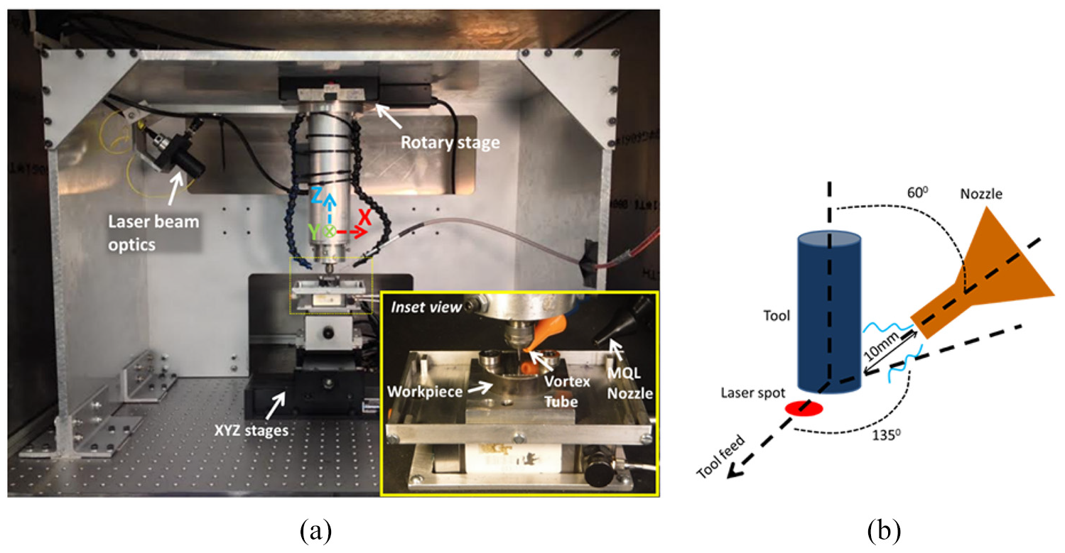
(a) Experimental setup for LAMM; inset shows a close-up view of the vortex tube and MQL nozzle delivery systems positioned around the micro end mill. (b) Schematic of the position and orientation of the MQL and vortex tube cooling nozzles.
In the setup, the laser head is mounted on a rotary stage fixed to the top of the gantry structure, enabling the laser beam to rotate 360° around the z-axis. A ytterbium-doped continuous-wave fiber laser (YLM-30; IPG Photonics, Oxford, MA, USA) with a Gaussian beam and a near infrared nominal wavelength of 1070 nm was focused to a 300 µm diameter spot located at a small predetermined distance from the leading edge of the tool. The cutting speed was derived from a variable high-speed electric spindle (NR-3060; Nakanishi, Japan) with a maximum spindle speed of 60,000 r/min. Three stacked linear motion ball screw stages (ATS-125 and AVS-105; Aerotech, Pittsburgh, PA, USA) were fixed to the top of an anti-vibration table and provided the workpiece feed motions. A piezoelectric force dynamometer (Minidyne® 9256C2; Kistler, Winterthur, Switzerland) was mounted on the stacked stages. In order to detect tool–workpiece contact, a uniaxial accelerometer (Model 8636C50, ±50 g range, 6 kHz frequency range, Kistler) was attached to the side of the dynamometer. The workpiece was fixed to the top face of the dynamometer. An MQL system (UNIST Coolubricator; UNIST Inc., Grand Rapids, MI, USA) was used to lubricate the tool using an atomized mixture of compressed air and oil (Coollube 2210EP, UNIST Inc.) delivered through a nozzle to the cutting zone as shown in the inset in Figure 1(a). A vortex tube system (610 Cold Air Gun; Vortec, Cincinnati, OH, USA) was fixed to the top of the gantry. The vortex tube takes in compressed air and outputs cold air through a nozzle.
Materials and experimental conditions
The workpiece material used in the experiments was a cold reduced round bar of precipitation hardened A286 steel (41.8 ± 0.6 HRC) commonly used in the production of aerospace fasteners. A286 is a high nickel content steel alloy with high tensile strength (1455 MPa), good corrosion resistance (oxidation resistance up to 700 °C), and good high-temperature creep resistance. It is composed of (by wt%) 56.8% Fe, 24.5% Ni, 14.1% Cr, 2.2% Ti, and small traces of other metals. The presence of abrasive hard carbide phases in the steel makes it difficult-to-machine, especially at the microscale.
Two flute, 500 μm diameter (nominal), square end, TiAlN-coated tungsten carbide end mills (MStar MS2SSD0050; Mitsubishi Materials U.S.A. Corporation, Mooresville, NC, USA) were used in the experiments. Each test was performed with a new tool.
Four parallel slots (grooves) were machined in each test. The first groove (Groove 1) was a shallow groove produced by a single pass of the tool at an axial depth of cut of 20 µm. The second and third grooves were deep grooves produced by 18 tool passes of 20 µm axial depth of cut per pass to yield a total groove depth of 360 µm. The fourth slot (Groove 4) was a shallow groove. The overall tool path in each test consisted of 38 tool passes, each 28.4 mm long and a depth of cut 20 µm, for a total cutting length of 1079.2 mm and total material removal volume of 10.8 mm3. All reported measurements were made on the first and fourth shallow grooves. The purpose of the second and third deep grooves was to induce tool wear.
This article focuses on the results for the following test combinations: (1) LAMM, (2) LAMM + MQL I, (3) LAMM + MQL II, (4) LAMM + Vortex I, and (5) LAMM + Vortex II.
Machining and laser parameter values were selected based on the previous work reported elsewhere. 34 Specifically, the machining parameter values consisted of a cutting speed of 16 m/min, 0.03 mm/tooth feed, and an axial depth of cut 0.02 mm. The laser power was set to 18 W with a corresponding peak intensity of 510 W/mm2, and the center of the 300 μm diameter laser spot was located 450 μm from the tool center. Two sets of MQL parameters, denoted as MQL I and MQL II, were selected based on prior work reported in the literature 20 and based on recommendations of the MQL system provider. The two vortex tube cooling tests, denoted as Vortex I and Vortex II, were based on the maximum flow rate and the maximum temperature concept.12,35 The specific parameters and their values for the MQL and vortex tube cooling assisted experiments are listed in Table 1.
Experimental conditions.
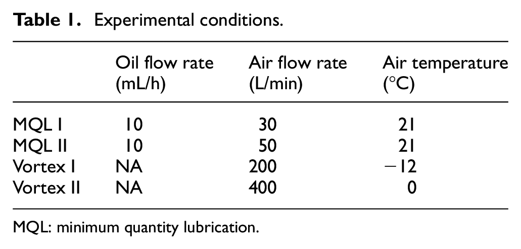
MQL: minimum quantity lubrication.
Assuming a simple cylinder in cross air flow to model a micro end mill subjected to vortex tube cooling, the Nusselt numbers for the flows represented by Vortex I and Vortex II were computed to be 17.2 and 23.3, respectively. Interestingly, Vortex II, which is characterized by a warmer but higher air flow rate, has the ability to remove more heat as suggested by the Nusselt numbers.
The MQL and vortex tube cooling nozzles were positioned approximately 10 mm from the tool tip at a yaw angle of 135° and a pitch angle of 60° relative to the direction of tool travel as shown schematically in Figure 1(b). Both MQL spray and vortex flow had a diameter of 10 mm or larger, and consequently, they not only impinged on the tool but also impacted the surrounding workpiece surface.
Measurement methods
All groove quality measurements were made on the shallow Grooves 1 and 4. Groove quality measurements were made using a confocal microscope (LEXT 3D; Olympus, Japan) and consisted of the groove dimensions (depth and width), burr dimensions (burr root thickness and height), and surface roughness. Tool diameter wear was measured using a toolmaker’s optical microscope. Tool wear at the bottom of the end mill was imaged in the confocal microscope. Flank wear of the tool’s peripheral cutting edges was imaged using a scanning electron microscope (SEM, S-3700N VP-SEM; Hitachi, Japan). Flank wear magnitude was quantified in an optical microscope (Microphot-FXL; Nikon, Japan). BUE on the tool was analyzed using the electron dispersive spectroscopy (EDS). Cutting forces were measured using the piezoelectric force dynamometer at a sampling rate of 30 kHz.
Results and discussion
Groove quality
Optical images of the surfaces of the first groove (Groove 1) are shown in Figure 2. Below each image is a representative cross-sectional profile of the groove. Since the first pass of each test was made with a new tool, the grooves have minimal chip adhesion, and their cross sections are relatively square. In addition, since the tool is new, surfaces of the groove floor have distinct tool marks. In the case of LAMM + Vortex I and LAMM + Vortex II, a dark vertical streak is visible along the groove centerline. This streak suggests the presence of a heat-affected zone (HAZ), which was confirmed through hardness measurements that yielded a hardness of 20.1 HRC in the dark region compared to ∼42 HRC near the groove walls. Thermal contraction due to cooler air produced by the vortex tube resulted in less than the full (0.02 mm) axial depth of cut. As a result, the tool did not remove all of the thermally softened material leaving behind an HAZ on the cut surface. The reason the HAZ is confined to the center of the groove is because of the Gaussian distribution of the laser irradiation, which produces the highest temperature at the center of the groove and lower temperatures away from it. It can be seen that the surfaces produced by LAMM + MQL I and LAMM + MQL II also exhibit HAZs. In the LAMM + MQL I and LAMM + MQL II tests, application of MQL resulted in a thin oil film on the workpiece surface prior to machining. Consequently, the oil film increased the absorption of laser radiation, which led to more heat penetration into the workpiece than in LAMM alone. Previous studies have shown that, in the presence of olive oil, the infrared laser absorption of stainless steels can increase anywhere from 37% 36 to 55%. 37 The MQL oil used in this study (Coollube 2210EP) is a natural vegetable oil, which is similar to olive oil. Note that prior work has demonstrated that the occurrence of HAZ in LAMM can be avoided through proper selection of laser power, laser spot size, and laser scan speed. 38
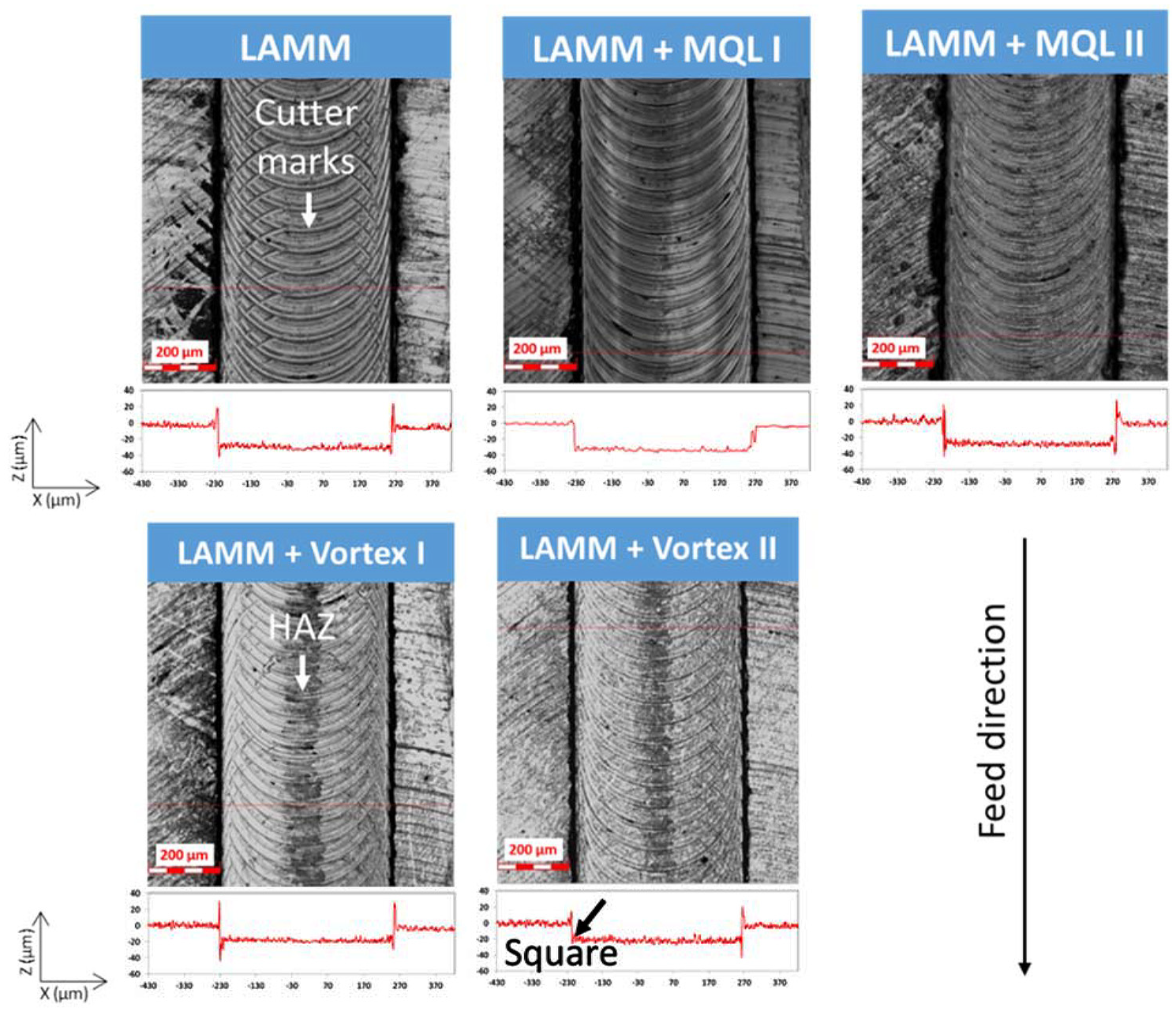
Surfaces of Groove 1 and corresponding cross-sectional profiles.
Optical images of the groove surface at the end of the tests (Groove 4) are shown in Figure 3. Due to progressive tool wear, the groove surfaces are characterized by chip adhesion, and have more tapered and rounded corners as seen in the groove cross-sectional profiles. Tool wear causes a burnishing action, which produces cutter marks that are less distinct than observed in Groove 1. The HAZ streaks are more pronounced in Groove 4 than in Groove 1. This is attributed to less material being removed by the worn tool, which leaves behind more of the HAZ. The MQL tests also yield larger burrs along the groove edges (see dark regions along the edges).
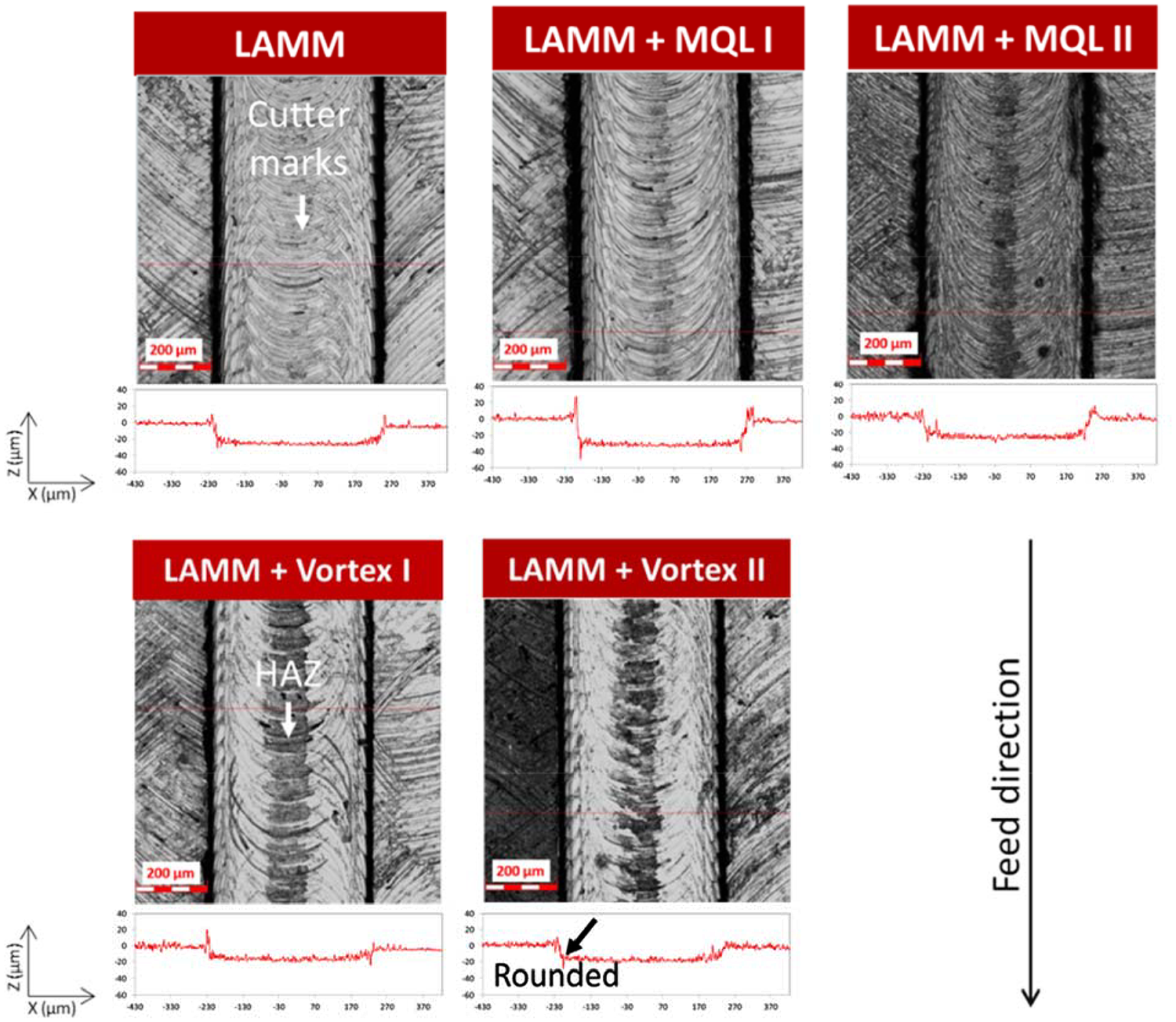
Surfaces of Groove 4 and corresponding cross-sectional profiles.
The groove width was measured in 10 different cross sections per groove per test condition. The groove depth measurements reported in this article are the averages of 500 depth measurements made along three different cross sections per groove per test condition.
Figure 4 shows the average depths of Grooves 1 and 4 for each test condition. Due to tool wear, the groove depth decreased from Grooves 1 to 4 in all test cases. The groove depths for LAMM, LAMM + MQL I, and LAMM + MQL II were found to be greater than the programmed axial depth (20 μm). As discussed elsewhere,34,38,39 this is due to thermal expansion of the tool and workpiece, which causes an increase in the axial depth of cut. Surprisingly, the axial depths of cut in LAMM + MQL I and LAMM + MQL II are greater than those in LAMM alone. This is again attributed to increased absorption of laser radiation by the thin MQL film on the workpiece surface, which generates higher temperatures and, in turn, more thermal expansion. On the contrary, LAMM + Vortex I and LAMM + Vortex II are characterized by less than or equal to the programmed axial depths of cut, depending on the cooling conditions. This is attributed to thermal contraction of the workpiece and, to a lesser degree, the tool due to impingement of cold air. Utilizing the thermal expansion coefficient of A286 and the temperature gradient in the workpiece produced by vortex tube cooling, it can be shown that there is a measurable contraction of the workpiece in the height direction, which impacts the axial depth of cut. It should be noted that the vortex tube cooling spot was approximately 10 mm in diameter, and therefore it impacted the tool and the surrounding workpiece. LAMM + Vortex II yielded a groove depth that was closest to the programmed depth. It should be noted that the under- or over-shoot in the axial depth of cut can be easily compensated for, provided the thermal expansion or contraction is estimated a priori.
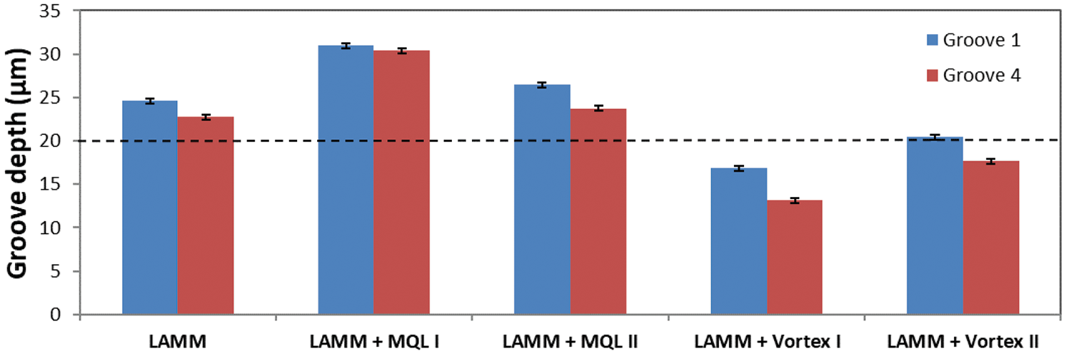
Groove depth measurements.
Comparing the widths of Grooves 4 and 1, the change in groove width for the different test cases is shown in Figure 5. It can be seen that the addition of MQL to LAMM reduces the change in groove width. This is due to the beneficial impact of MQL on tool wear. Compared to LAMM, the LAMM + MQL II test yielded a 41% smaller change in groove width. Interestingly, LAMM + Vortex I and LAMM + Vortex II produced larger changes in groove width, which is attributed to reduced thermal expansion of the tool and the workpiece (due to vortex tube cooling) and due to increased diametric wear of the tool (as shown later in Figure 9).
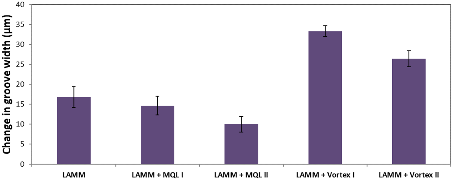
Change in groove width.
Burr root thickness was characterized by the burr width at the base of the burr. Burr height was measured from the top plane of the workpiece surface to the highest point of the burr.40,41 For each test condition, burr measurements were made for Grooves 1 and 4 at five different cross sections on the left and right sides of the groove for a total of 10 measurements per groove. The resulting average burr root thickness is shown in Figure 6, and the average burr height is shown in Figure 7. Although the burr dimensions exhibit significant variation, some general trends can be discerned. In the absence of significant tool wear (Groove 1), the addition of MQL and vortex tube cooling mostly resulted in reductions in the burr dimensions compared to LAMM, albeit to different extents depending on the MQL and vortex tube cooling conditions utilized. An exception is the burr height for LAMM + MQL II, which does not show a significant reduction in burr height in the absence of tool wear. The reductions may be attributed to possible lowering of temperatures in the cutting zone due to MQL and vortex tube cooling, and consequent reduction in the ductility of the work material. In the presence of tool wear (Groove 4), the burr dimensions generally increased with the addition of MQL and vortex tube cooling compared to LAMM. This may be explained by the increase in cutting zone temperatures due to tool wear, which has a greater influence on the ductility of the work material than the lubrication and cooling effects of MQL and vortex tube cooling, respectively.
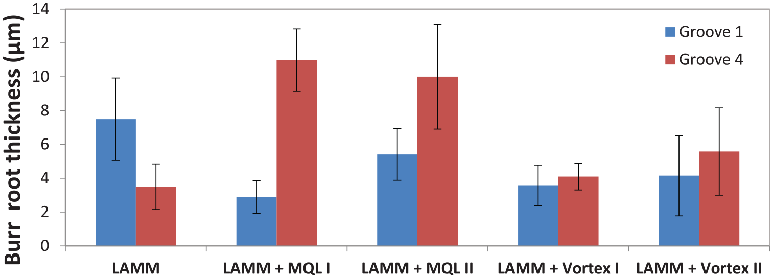
Burr root thickness results.
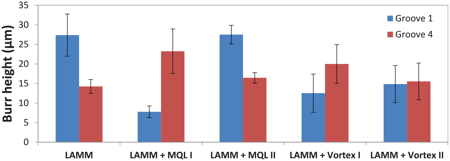
Burr height results.
The areal arithmetic average surface roughness height (Sa) of the groove floor for each test condition is shown in Figure 8. It can be seen that in most cases, the surface roughness of Groove 1 was greater than Groove 4. When the tool was new and sharp, it left distinct cutter marks on the surface. But as the tool corner radius and cutting edge wore, the burnishing action of the tool tended to decrease the roughness. This can be seen from the optical images of the cut surfaces in Figures 2 and 3. LAMM + MQL II yielded the lowest surface roughness, which did not change significantly with tool wear.
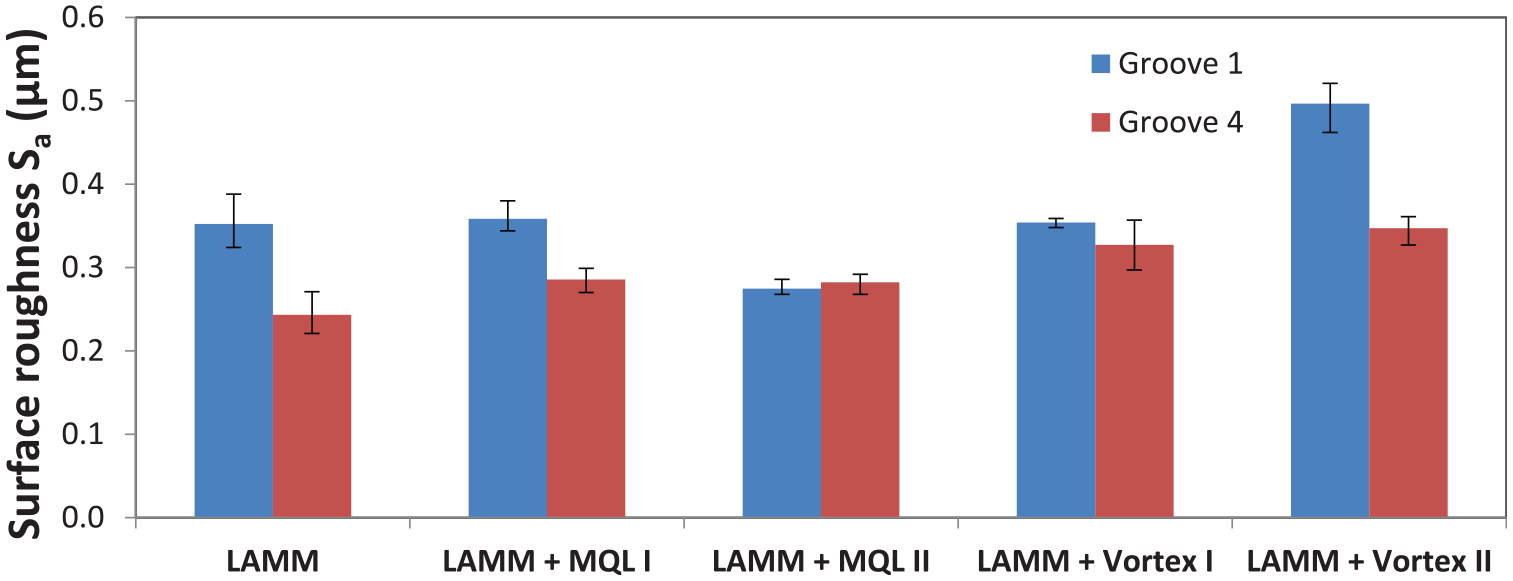
Areal arithmetic average surface roughness height (Sa).
Tool condition
Tool diameter was measured optically at the axial depth of cut, that is, 20 µm along the tool axis measured from the tool tip, and the results are shown in Figure 9. It can be seen that LAMM + MQL II yielded the smallest change in tool diameter, and hence the least wear. The tool corner radius results are similar, as reported elsewhere. 42 Reduction in tool wear from the use of MQL in macroscale laser-assisted milling has also been reported by Bermingham et al. 32
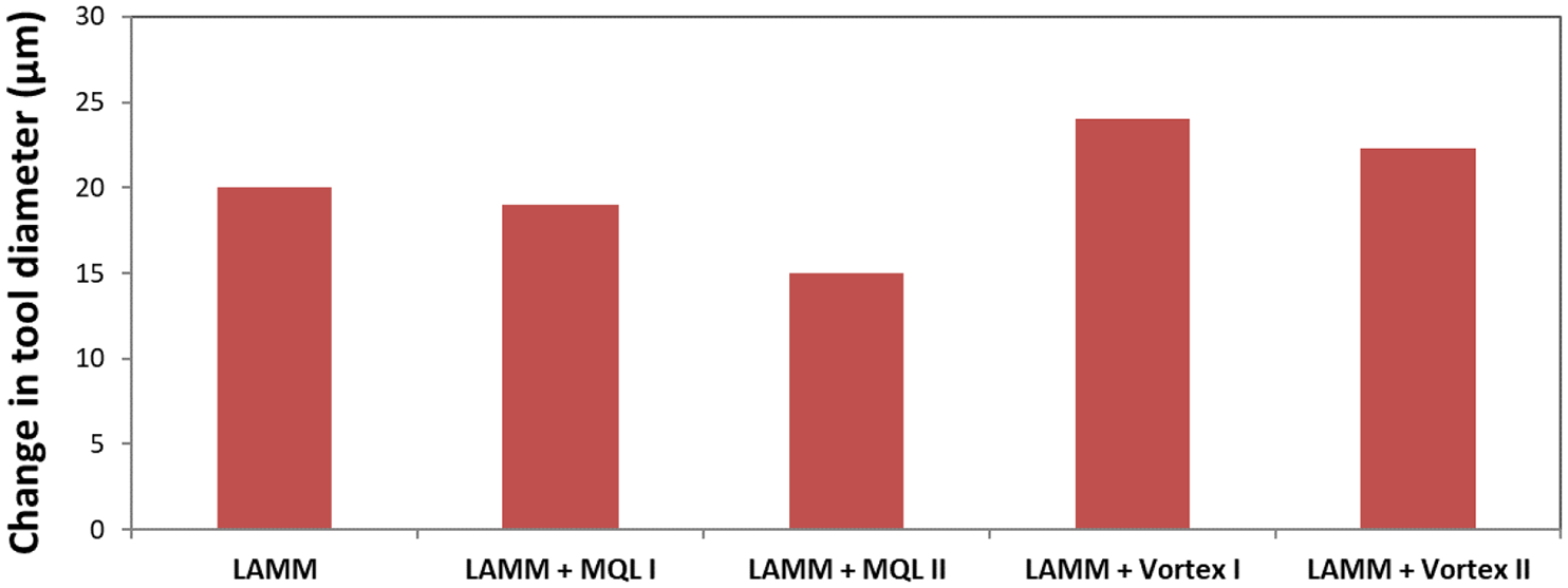
Change in tool diameter.
SEM images of the peripheral edge of the tool after each test are shown in Figure 10. Visible BUE is seen in the LAMM, LAMM + Vortex I, and LAMM + Vortex II tests. The BUE is more prominent in these tests because the workpiece is thermally softened and is thus more prone to adhesion. The BUE will eventually break off and take with it some of the coating, or even chip the tool, thereby accelerating wear. Other researchers have also reported increased work material adhesion in macroscale laser-assisted milling. 32 Interestingly, no BUE was seen in the LAMM + MQL I and LAMM + MQL II tests. This is attributed to the enhanced tool surface lubrication by the MQL fluid. This is also the reason that LAMM + MQL II yielded the smallest change in tool diameter, as shown in Figure 9.
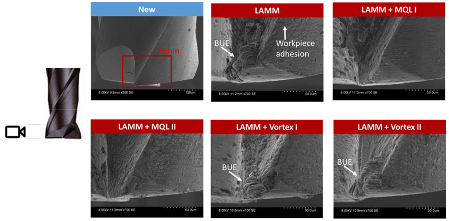
SEM images of the peripheral cutting edge of tool showing wear and built-up edge.
As seen in Figure 10, a flank wear scar can be observed along the peripheral edge. As reported elsewhere, 42 analysis of the maximum width of flank wear showed that LAMM + Vortex I did slightly better than the other cases, albeit only marginally.
EDS was conducted on the tools used in the LAMM and LAMM + MQL II tests to confirm that the material adhering to the tool surfaces was indeed BUE. Figure 11 shows the EDS maps. It can be seen that LAMM is characterized by a large clump of Fe (from A286) welded to the tool tip and around the cutting edge. In contrast, LAMM + MQL II shows no work material buildup. Yet, in both cases, some of the tool coating is worn away exposing the tungsten base.
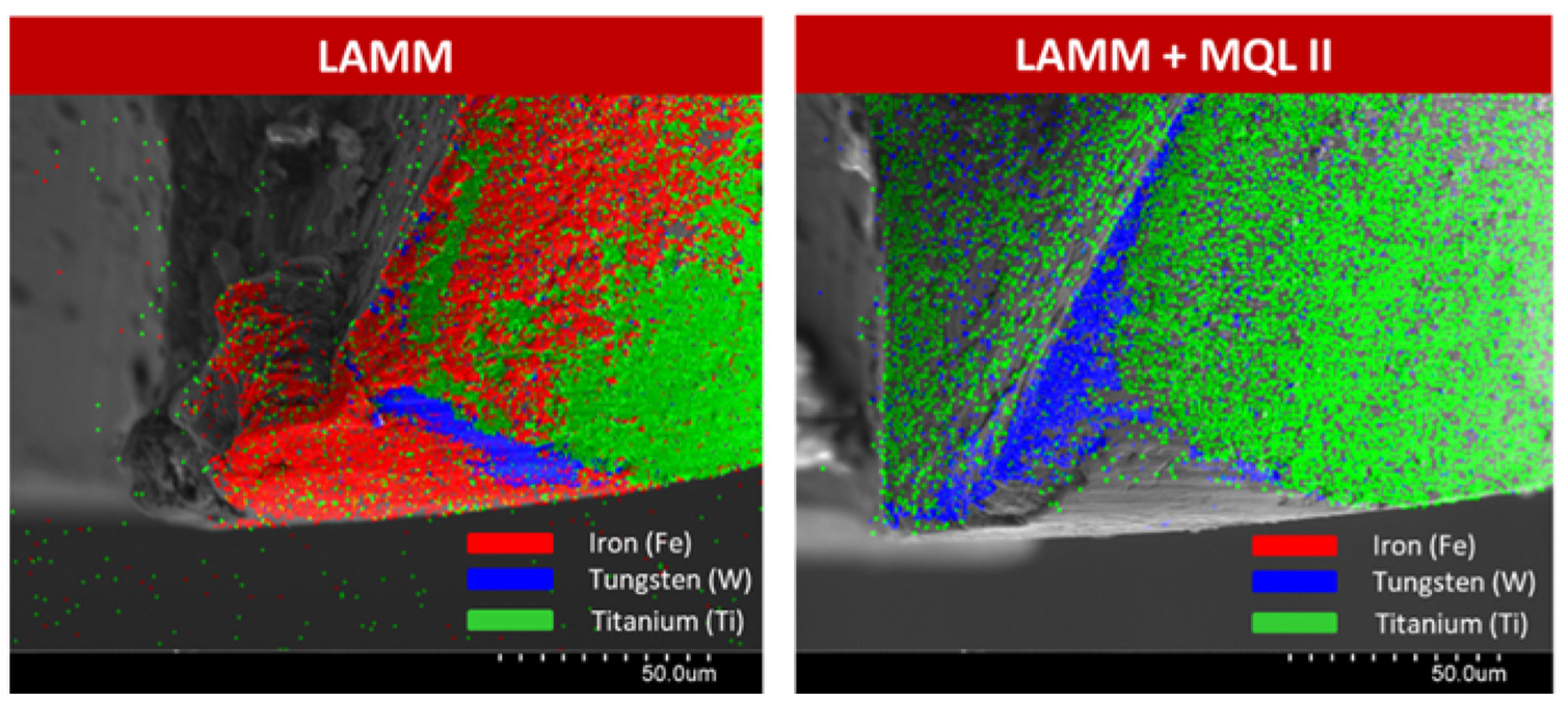
EDS maps for LAMM (left) and LAMM + MQL II (right).
Quantitative analysis of the EDS maps revealed that almost 45 wt% of the mapped area of the tool used in the LAMM test consisted of chemical elements from the workpiece material, indicating significant workpiece adhesion. 41 In comparison, the LAMM + MQL II test only had 23 wt% of A286 elements, implying considerably less work material adhesion. The LAMM + MQL II test also preserved more of the tool coating than any other test, as seen from the greater presence Ti in the EDS maps. Compared to LAMM, the LAMM + Vortex I and the LAMM + Vortex II cases did only marginally better in minimizing workpiece adhesion. 42
Cutting forces
The average resultant forces for the five test conditions are shown in Figure 12. As expected, due to tool wear, the resultant force was always higher for Groove 4 than for Groove 1. Comparing the results for Groove 1, LAMM + Vortex I yielded the lowest average resultant force. Groove 4 was a better indicator because it showed how each test condition affected the cutting forces after a prolonged period of cutting. In comparison to LAMM, LAMM + MQL II lowered the resultant force only slightly. Compared to LAMM, LAMM + Vortex I and LAMM + Vortex II yielded the highest (∼15%) reductions in the average resultant force.
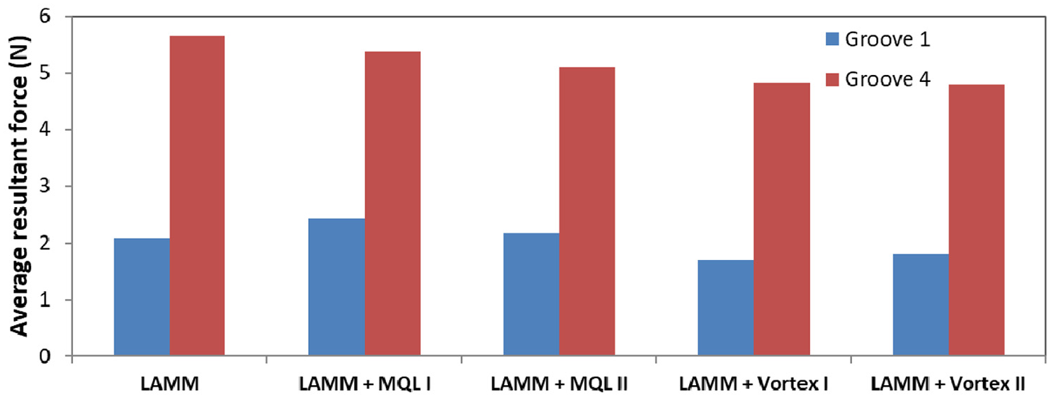
Average resultant force.
Conclusion and future directions
This article investigated the use of MQL and vortex tube cooling in the LAMM process to mitigate BUE formation and further enhance micromachinability of a high nickel content stainless steel (A286). The main conclusions of the study are as follows:
Compared to LAMM, LAMM + MQL II resulted in a smaller change in groove width, implying better groove dimensional accuracy. On the contrary, the groove depth was larger than the nominal depth in all LAMM + MQL cases due to increased absorption of laser irradiation by the workpiece in the presence of the MQL film.
Vortex tube cooling generally produced shallower and narrower grooves, which is attributed to thermal contraction of the workpiece.
LAMM + Vortex tube cooling generally reduced the burr size, while LAMM + MQL increased the burr size.
When using MQL, a higher air flow rate (as in LAMM + MQL II) allowed for better lubrication of the tool surfaces and less BUE on the tool.
LAMM + MQL II yielded the smallest change in tool diameter due to wear.
Compared to LAMM alone, LAMM + MQL II and LAMM + Vortex II reduced the average resultant force by an additional 10% and 15%, respectively.
Overall, LAMM + MQL II was found to be the best condition with the least amount of tool wear, minimum BUE, and the smallest change in groove width.
The above enhancements in micromachinability of the difficult-to-cut stainless steel obtained through the use of MQL in LAMM can benefit mass production applications, particularly in the aerospace industry where micromachining of A286-based products such as fasteners is known to be difficult and costly.
This work opens up opportunities for further investigations of micromachinability enhancement in LAMM. Specifically, a HAZ was observed in the LAMM + MQL cases, but not when using LAMM alone. Consequently, a better understanding of how MQL alters the absorption of laser irradiation is required to prevent a HAZ. While the effect of cryogenic cooling on machinability enhancement in macroscale LAM has been reported, 31 similar studies at the microscale are lacking and should be pursued. Finally, there is merit in investigating the use of cryogenic cooling using either liquid nitrogen or liquid carbon dioxide to enhance micromachinability of difficult-to-cut materials in LAMM. Recent work on dual cryogenic jets to enhance machinability in conventional turning of a titanium alloy points to a potential pathway to adapt this cooling approach to benefit the LAMM process. 43
Footnotes
Appendix 1
Acknowledgements
The first author would like to acknowledge the assistance of A. Bucciarelli in preliminary experimental work that led to the present study.
Declaration of conflicting interests
The author(s) declared no potential conflicts of interest with respect to the research, authorship, and/or publication of this article.
Funding
The author(s) disclosed receipt of the following financial support for the research, authorship, and/or publication of this article: This work was sponsored by Alcoa Fastening Systems & Rings (now a division of Arconic).