
Abstract
Broaching operations require stiff machine tools that have to withstand high cutting forces. This work aims to develop a methodology to predict the macroscopic cutting forces on a real, internal broaching operation comprising a large number of teeth. The macroscopic forces are estimated, based on the addition of local forces that are applied to each section and are simultaneously in contact with the broach. These local forces are calculated using a model of specific cutting pressure, depending on the rise per tooth. This study uses two methods to identify this specific cutting pressure model, that is, a direct approach based on orthogonal cutting tests and an inverse approach based on an instrumented broaching operation. It is shown that the direct method is effective in identifying a specific cutting pressure model and enables the prediction of macroscopic forces. Moreover, the direct approach provides more comprehensive results in terms of radial forces.
Introduction
Since the 19th century, the broaching process has been commonly used to rapidly generate complex, accurate surfaces (IT7) and good surface finishes (Ra ≈ 0.8 μm). Broaching consists of progressive material removal using a special tool, known as a ‘broach’, and it, generally, has a linear movement (Figure 1). 1 The broaching can be internal, if the tool operates within a hole, or external, if the tool operates on an open surface.
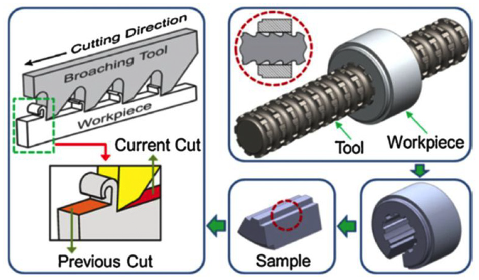
Principle of broaching. 1
The basic principle of broaching is close to an orthogonal cutting operation (Figure 2). A tool (broach) is composed of several teeth with different heights HD. The difference between two heights generates a rise per tooth h. Chips are generated at the rake face (with a rake angle γ) and stored in a chip chamber. The distance between two teeth is known as the pitch P. In order to avoid severe friction, teeth are sharpened with two clearance angles: α on the relief face and αoe on the flank face.
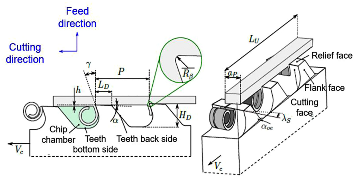
Description of a basic broaching operation.
The main differences to the conventional methods of machining (milling, turning and so on) are the very low cutting speed (usually a few m/min) and the very thin chips that vary between 1 μm, for finishing teeth, and 40 μm, for roughing teeth. Even though broaching is commonly used in the aeronautical and automotive industries, limited research has been carried out on this process compared to conventional processes. This is due to the limited number of applications that can be used to produce at a very large scale, leading to a very stable and low cost per part. Moreover, during a defined broaching operation, all the parameters are predetermined in advance, especially the design of the broach. Then, in front of the machine, it is only possible to modify the cutting speed and lubrication to a limited extent. Nevertheless, it may take several months to find the right design for the broach, based on experience and trial and error. As more emphasis is placed on productivity and part accuracy, modelling becomes a key issue. End users are interested in the modelling and prediction of the quality and cost of broaching operations. Among the parameters to be modelled, forces are of primary importance in order to predict the ability of the machine to manage the operation (the power of the axis and structural deformation), as well as to predict part deformation and broach wear.
A significant number of scientific investigations have focused on the variation of forces during a single tooth broaching operation, which corresponds to a well-known orthogonal cutting configuration (Figure 3). Each tooth has to withstand two elementary forces: a cutting force Fc and a radial force Fr (Figure 4(a)).
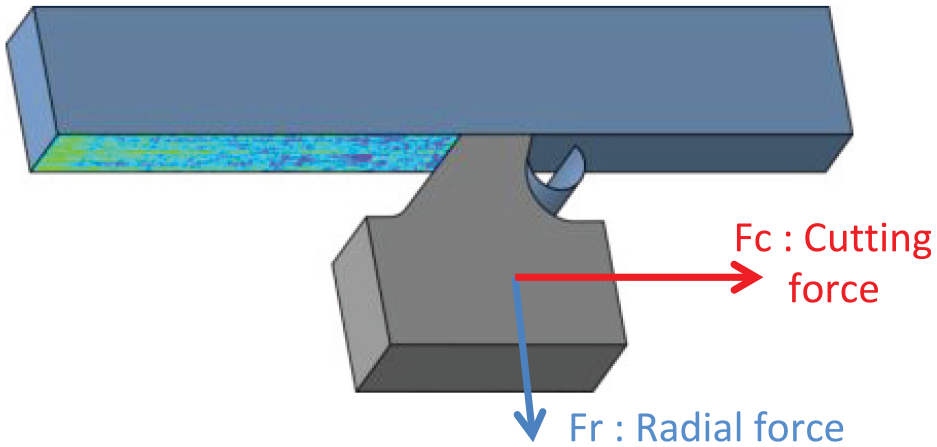
Principle of an elementary orthogonal cutting operation.
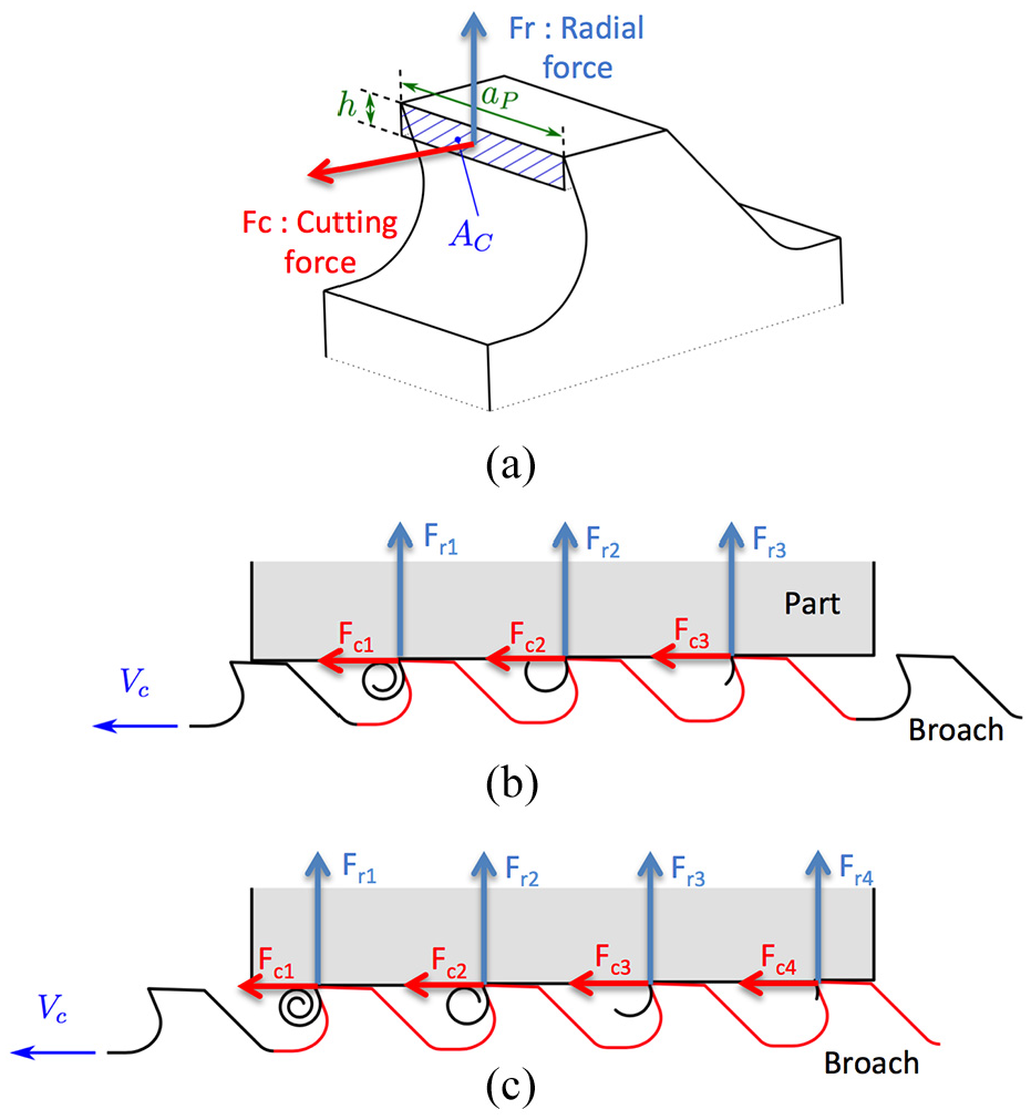
Model of cutting and radial forces for (a) a single tooth broach and (b and c) multiple teeth broaches.
Several works2–6 have developed finite element models (FEMs) to predict both components, but their accuracy faces problems due to the very small chip thickness, that is, within the same order of magnitude as the grain size of the material. Moreover, the very low cutting velocity leads to serious limitations regarding friction models at the tool–material interface. Finally, most of these FEMs2,3,5,6 are concerned with milliseconds, which do not enable them to take into account the contribution of the rolling up of the chip inside its chamber. Fabre et al. 4 have proposed a preliminary scientific contribution to consider this phenomenon.
Many works have identified empirical models using an experimental setup close to an orthogonal cutting operation (Figure 3).6–17 They model cutting and radial forces on the basis of equations (1) and (2), using the traditional specific cutting pressure kcc and the specific radial pressure kcr
where Ac is the area of chip section (in mm2), equals h × ap (Figure 4).
Specific pressures kcc and kcr are identified using an experiment for each configuration (work material⇔tool substrate⇔lubrication) by considering the most sensitive parameters, that is, the rise per tooth, the cutting speed and the rake angle. These experiments lead to a surface response for each specific pressure of kcc and kcr.
These empirical models are very accurate in predicting the forces of an orthogonal cutting operation. The problem is verifying whether these simple models may be used to estimate the macroscopic forces on real broaches with complex and curved geometries, that is, with a variable rise per tooth and rake angles. Theoretically, the macroscopic forces Fc and Fr applied to a real broach can be determined by adding the elementary forces acting on each tooth, as illustrated in Figure 4(b) and (c)
The weakness of this method is related to the fact that orthogonal cutting tests consider a single straight cutting edge in contact with the workpiece and oriented perpendicular to the cutting direction. The work material is supposed to flow in a plane that is perpendicular to the cutting edge (plane strain deformation). On this basis, it is assumed that a complex cutting edge can be divided into several elementary straight cutting edges and working in orthogonal conditions. Moreover, these elementary forces are assumed to be independent from each other. This is a strong assumption. Indeed, real cutting edges are curved, which disturbs the chip flow. For instance, when broaching an internal cylinder (Figure 5), a chip begins to be generated by a concave surface (rake face). Then, its curvature is suddenly modified into a convex surface due to the interaction with the gullet (the core of the broach). This modification of the curvature induces a high load on the teeth that is not considered in the elementary orthogonal cutting approach with straight edges. Figure 6 illustrates that the bending moment Mfx of a straight edge differs significantly from the bending moment of a curved edge. This difference can be even larger if the section is not homogeneous, which strengthens the chip. In practice, this problem is solved empirically by broach manufacturers using chip breakers (Figures 5 and 7). Using ‘enough’ chip breakers, it is possible to consider small curved cutting edges as behaving like straight edges, making it possible to apply the orthogonal cutting force models (Figure 7).
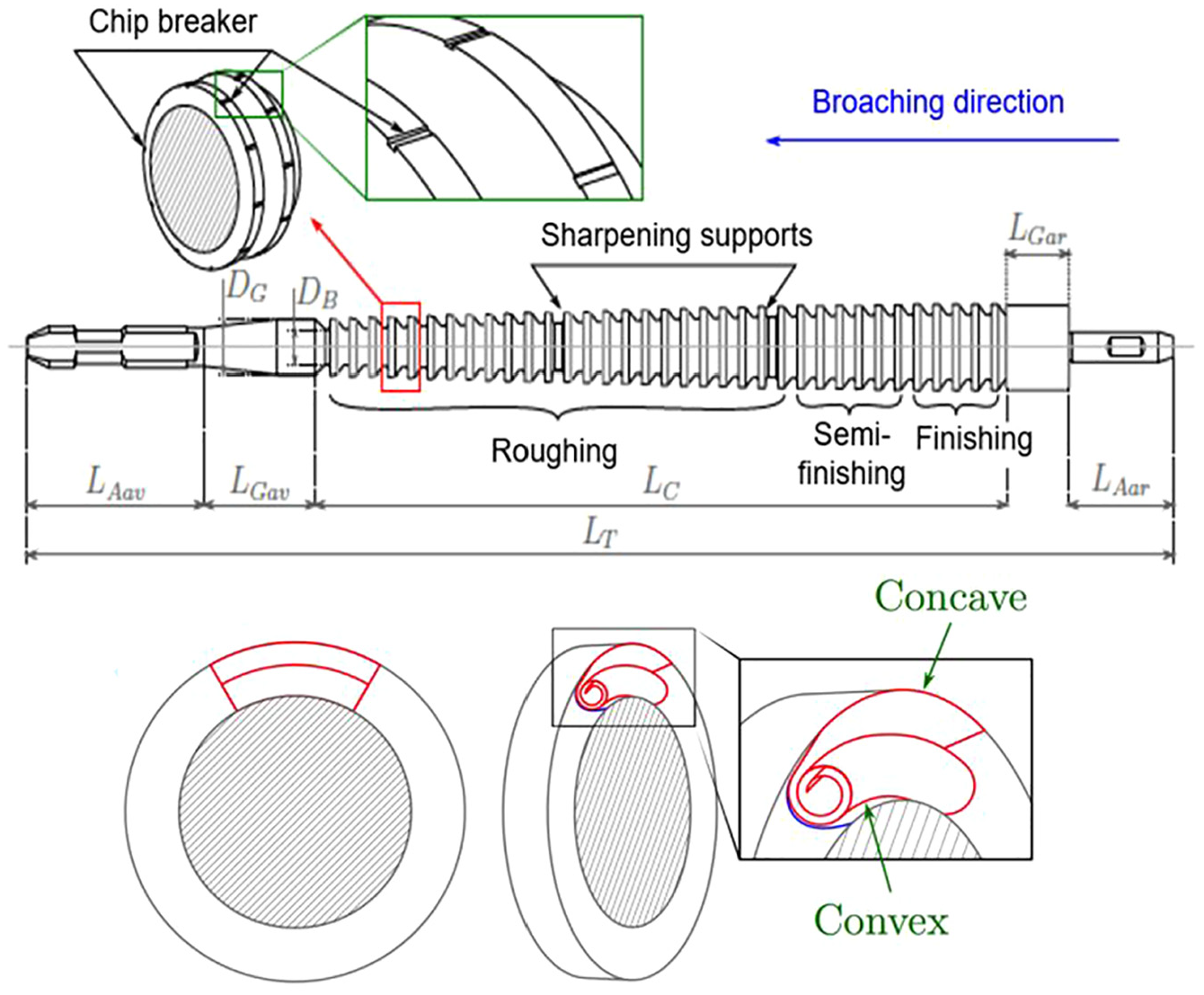
Example of an internal broach and the curvature of chip flow.
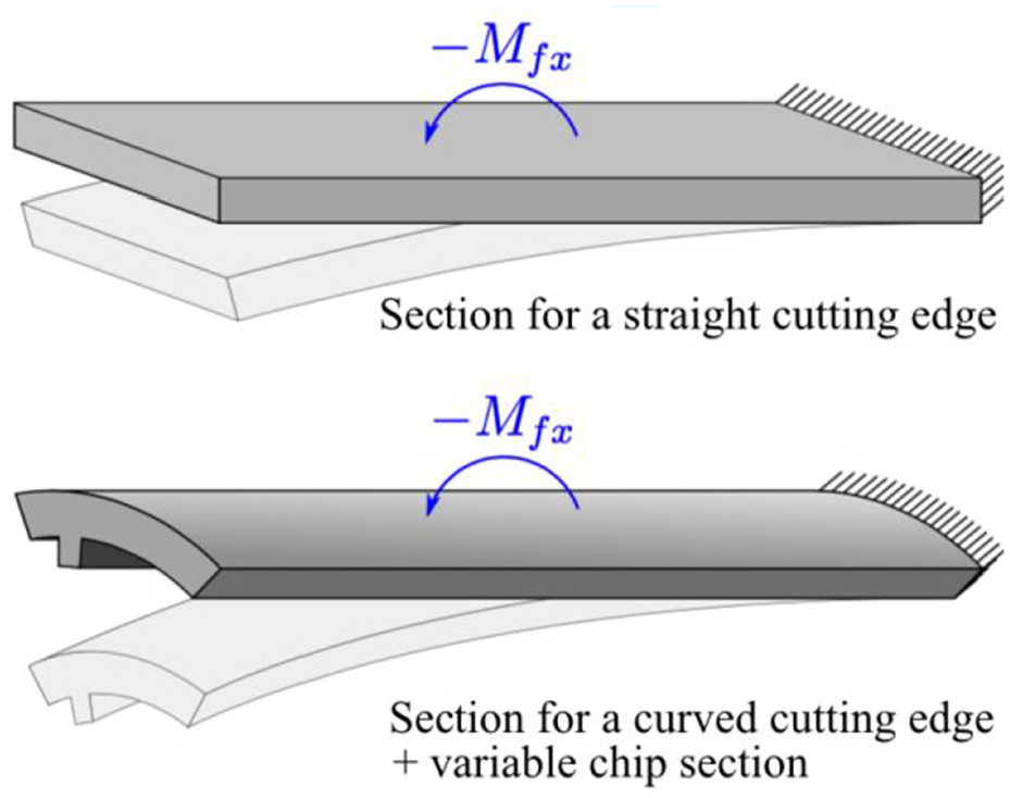
Illustration of the bending moment with straight and curved cutting edges.
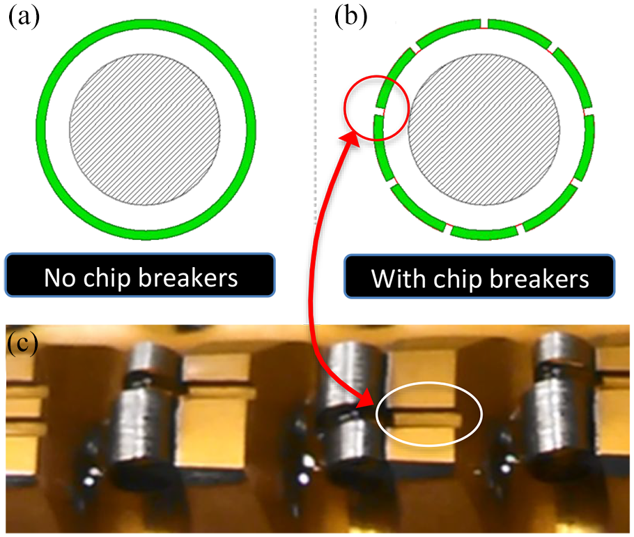
A broach (a) without chip breakers and (b and c) with chip breakers.
As a result, some scientists have decided to use this approach. For instance, some researchers 18 developed a model to predict macroscopic cutting forces in a gear broaching operation. A similar work is presented in Ozlu et al. 19 and Vogtel et al. 20 for a fir-tree broaching operation.
Another approach is to carry out a real broaching operation with industrial parameters (real broach, parts and lubrication) and to monitor the forces. By analysing the signal, it is theoretically possible to identify the force for each tooth. Indeed, Figure 4(b) and (c) shows that the number of teeth varies over time. Thus, it is possible to discriminate the contribution of each tooth inside the signal. As the section to be removed by each tooth is known, an inverse calculation should be able to identify kcc and kcr for each tooth. Moreover, as the rise per tooth varies between roughing, semi-finishing and finishing teeth, it is theoretically possible to identify a model of kcc and kcr depending on the rise per tooth. Of course, this approach requires accurate manufacturing of the broach. Moreover, rake angles have to be kept constant, which is usually the case, as a single rake angle is selected for a given work material and tool’s substrate. This inverse approach integrates potential interactions with the gullet during chip formation, but it does not enable identification of the effects of cutting speed and rake angles. Moreover, as far as internal broaching operations are concerned, this inverse approach does not enable the identification of a specific radial pressure kcr model, because the radial forces are counterbalanced. From the available literature, no scientific study appears to have investigated this approach.
Therefore, the objective of this work is to challenge the two methods (a direct approach, based on orthogonal cutting tests, and an inverse approach, based on a real broaching operation that is monitored) to identify elementary cutting force models with the objective of applying them during the prediction of macroscopic cutting forces in broaching. As mentioned previously, the identification of the specific radial pressure model is not possible in the case of the inverse approach. Thus, this work will challenge the two methods by analysing the cutting force only.
The study starts by identifying a specific cutting pressure model based on an orthogonal cutting operation. Then, a real broaching operation will be monitored in order to identify another elementary model. Both models will be compared. Finally, their ability to predict real macroscopic internal broaching forces will be assessed.
Identification of force models with orthogonal cutting tests
The experimental setup is presented in Figure 8. A four-axis machining centre with a horizontal spindle was used to carry out the broaching experiments. The spindle was equipped with a specially designed workpiece holder and a clamping system mounted on a dynamometer to maintain the broaching tool. In order to limit the disturbances induced by the entry/exit of broaching tool teeth, tests were carried out with a single tooth cutting tool.
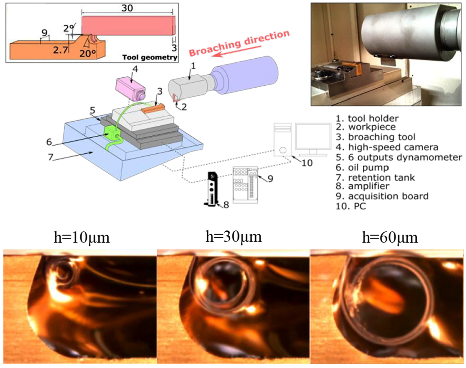
Experimental setup for elementary orthogonal broaching operations.
The study of force evolution concerns the broaching of an X12Cr13 stainless steel workpiece with a HSS M35 tool, TiN-coated on the flank face only. The rake angle is γ = 20°, the clearance angle is α = 2° and the cutting edge preparation is Rβ = 6°. The broaching speed is 2.5 m/min, and the straight oil is used with a flow rate of 400 L/h.
As shown in Fabre et al., 9 each test takes approximately 0.7 s. Cutting forces become stable after approximately 0.2 s, so the values of kcc have been averaged between 0.2 and 0.7 s. Tests were replicated five times. The error bars presented in the following curves are obtained through a Student’s law with a 0.9 cumulative probability. Figure 8 plots some of the chips obtained after broaching. As reported by Fabre et al., 9 the chip rolling diameter increases with the rise per tooth.
Figure 9 plots the evolution of the calculated specific cutting pressure kcc over the rise per tooth h within the broad range of 0.01–0.05 mm. The curve has a conventional shape, similar to the one presented in Fabre et al. 9
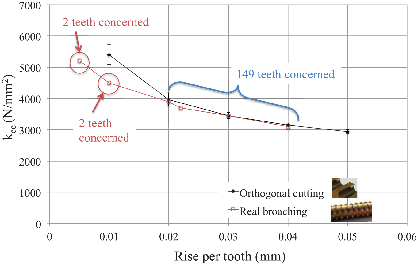
Evolution of specific cutting force over the rise per tooth.
Identification of force models by inverse method
The broaching operation was carried out on an industrial horizontal broaching machine. The industrial application corresponds to the manufacture of a plate-maintaining tube in a nuclear steam generator, as illustrated in Figure 10. Each plate has ∼12,000 holes that are pre-drilled so as to guide the broach. The shape of the profile to broach is presented in Figure 10. The broaching machine is equipped with a dynamometer that measures the macroscopic cutting force.
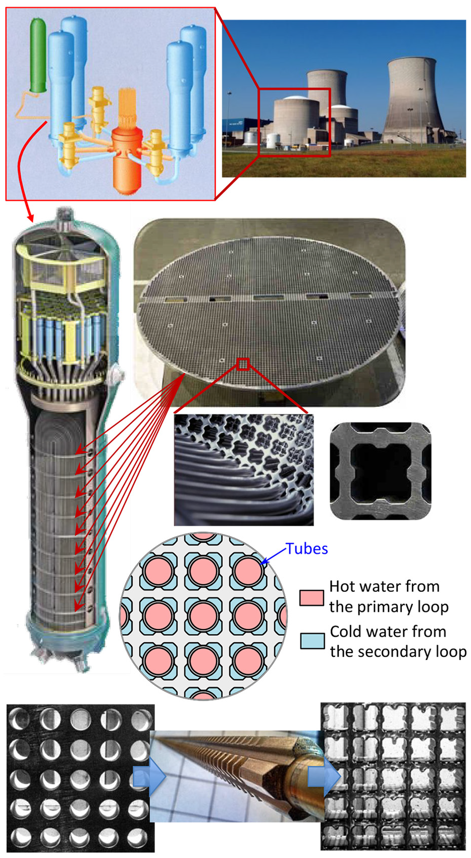
Industrial application of the broaching operation.
Figure 11 presents the shape of the broach and the evolution of 153 teeth profiles, which can be divided into five different types. The pitch of the broach is P = 8 mm, the rake angle is γ = 20° and the clearance angle is α = 2°. The broaching speed is 2.5 m/min.
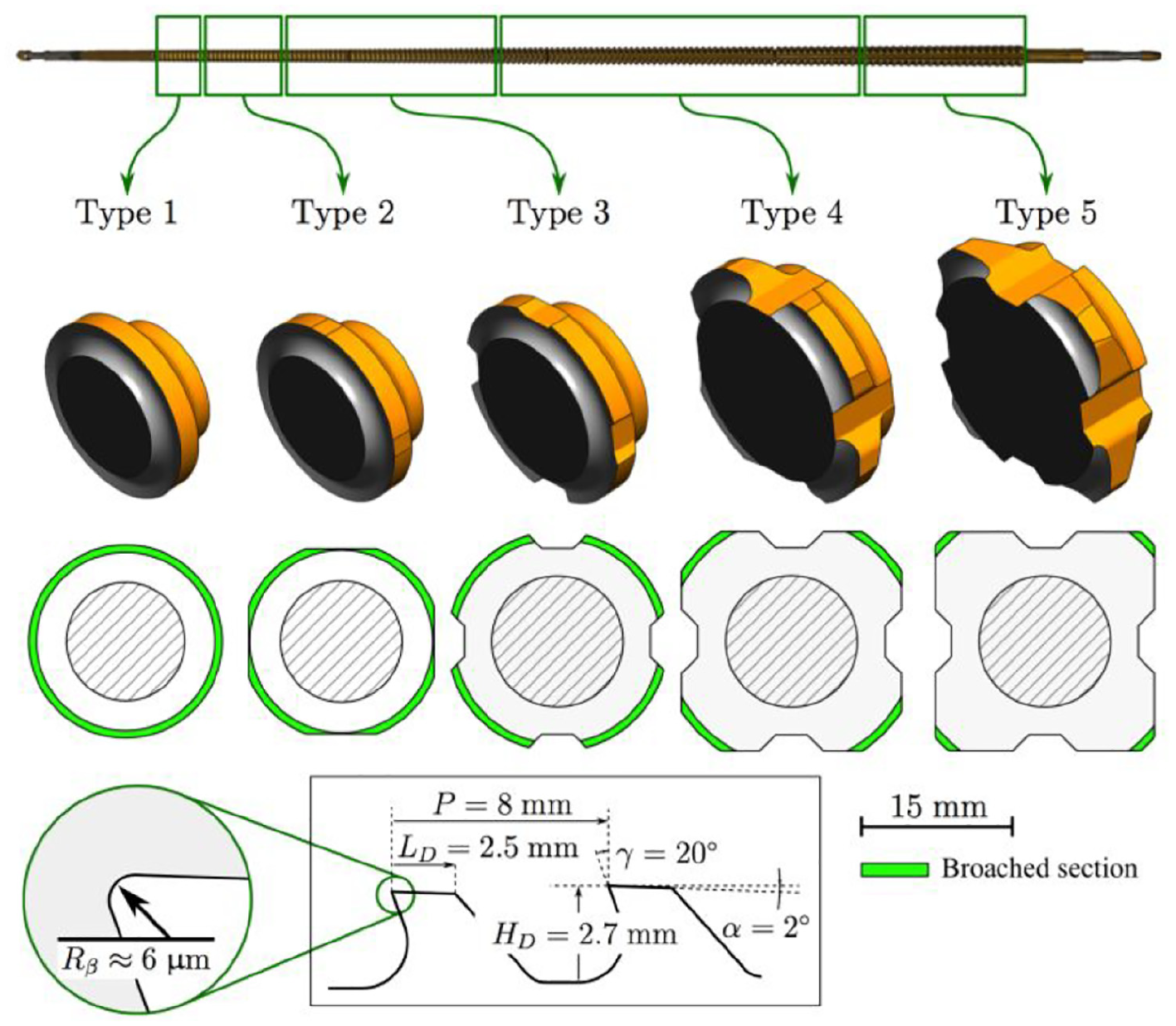
General overview of broached sections along the broach.
The evolution of the macroscopic cutting force is plotted in Figure 12. The five types of teeth lead to different levels of cutting force. For each type, the cutting force oscillates due to the variation of the number of teeth in contact with the part mentioned in Figure 4. The three zones necessary to maintain this very long broach during resharpening operations (sharpening supports are shown in Figure 5) are clearly visible as it leads to a sudden decrease in the cutting force. As expected, the roughing teeth at the beginning of the broach provide higher cutting forces, whereas the finishing teeth induce lower forces at the end, which enables the limitation of part deformation to calibrate the geometrical accuracy.
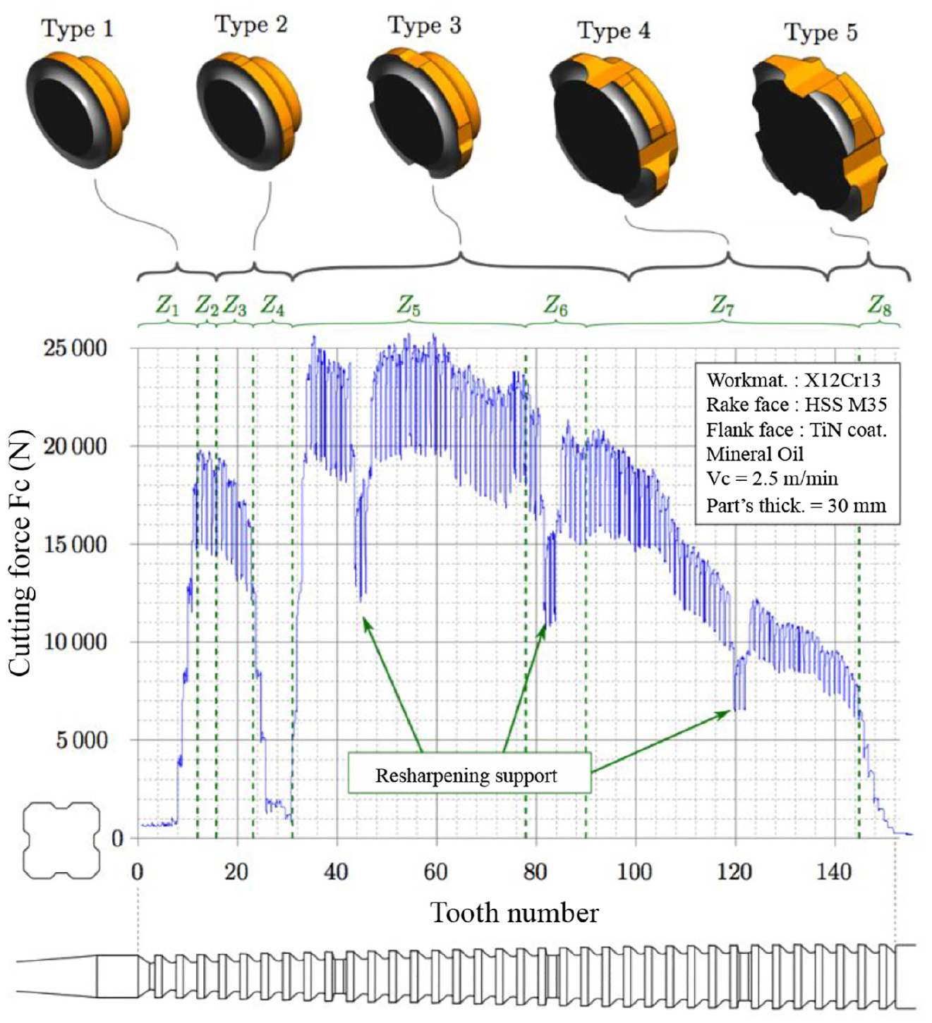
Evolution of macroscopic force in broaching.
By following the evolution of the cutting force, it becomes possible to calculate the evolution of the specific cutting pressure kcc due to the broached section of each tooth, in accordance with equation (1).
Figure 9 plots the evolution of the calculated specific cutting force kcc over the rise per tooth h within a broad range between 0.005 and 0.04 mm, corresponding to the design of the broach.
Comparison of specific cutting forces
Figure 9 plots the comparison of the specific cutting forces kcc identified by orthogonal cutting tests or by reverse engineering in broaching. The results are very similar for the range of the rise per tooth (0.02–0.04 mm), which corresponds to the majority of the sections (149 out of a total of 153). There is a clear difference for the smallest rise per tooth, in which the orthogonal tests overestimate the specific cutting pressure kcc. The reason for this has not been investigated in detail as it only concerns 2 + 2 teeth of the 153 teeth in the broach. Moreover, these low values of rise per tooth correspond to finishing teeth at the very far end of the broach, for which the cutting force is very low. Thus, the consequences of this weakness are not significant.
Finally, it can be concluded that the direct method is capable of identifying a relevant specific cutting pressure model. This method has the advantage of identifying a model very quickly (in 1 day). Moreover, a machining centre is much cheaper and is more accessible than a broaching machine. Elementary cutting tools for orthogonal cutting tests are also easier and cheaper to produce. In addition, it becomes easier to investigate more parameters (such as rake angle and relief angle) to make the specific cutting pressure more accurate. Moreover, it also provides the data that allow us to identify the specific radial pressure model, which is of interest for external broaching operations when part accuracy is addressed.
Prediction of cutting forces in internal broaching
Based on the evolution of kcc (identified by the orthogonal cutting tests), a direct calculation of the theoretical macroscopic cutting force has been made and compared with the experimental one, as shown in Figure 13. It appears that the predicted evolution of the macroscopic cutting force is remarkable.
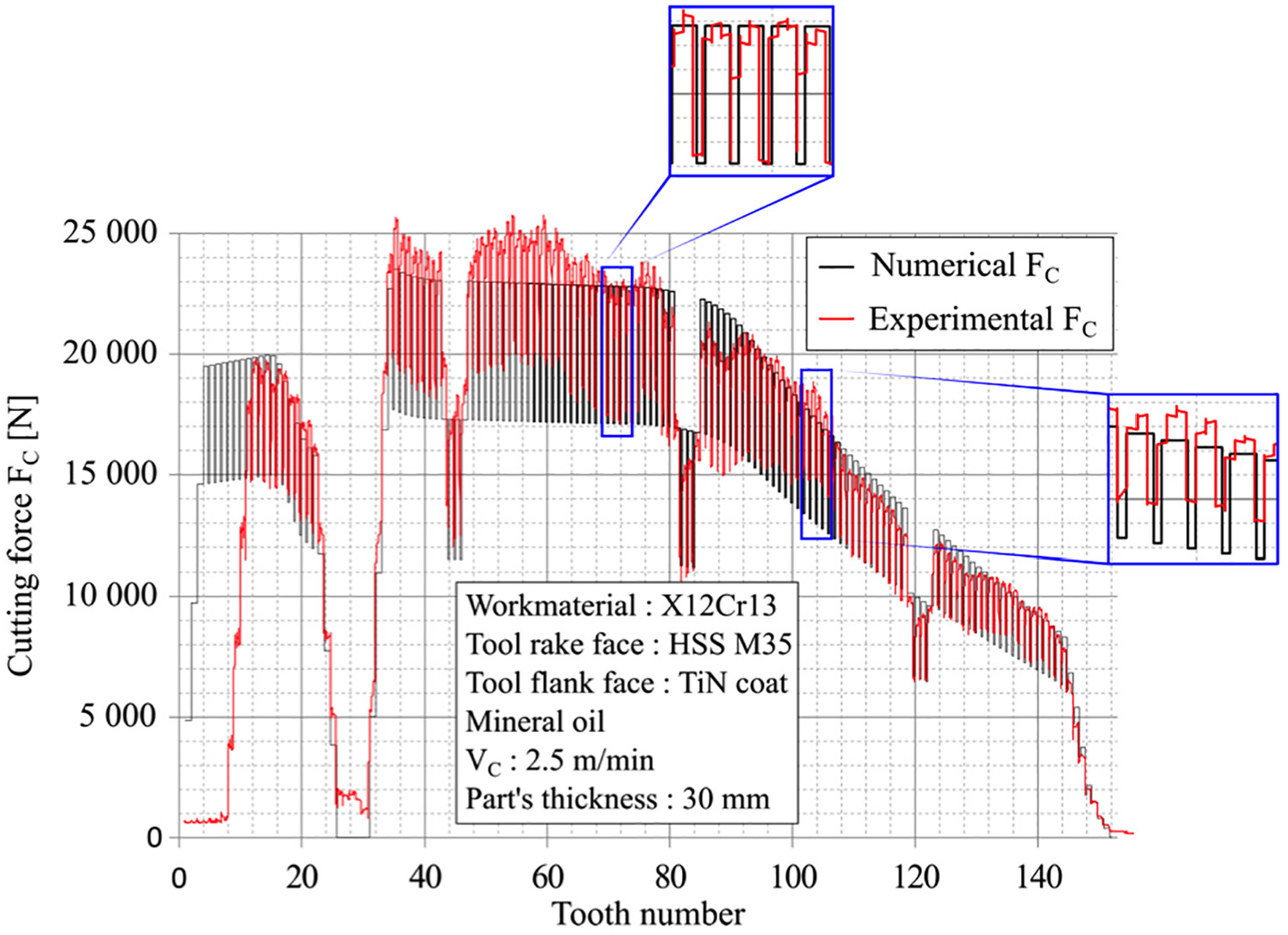
Comparison of numerical and experimental macroscopic forces in broaching.
For the first teeth, no experimental signal is measured because the preliminary hole was larger than the theoretical one, which does not enable the broach to cut. In the type 5 regions (teeth numbers from 30 to 80), the model underestimates the experimental values but the difference is smaller than 10%. This difference may be due to errors in the broach’s straightness or a lack of chip breakers, which increases the local cutting forces through an increase in the bending moment in curl curved chips, as mentioned previously. However, reasonable accuracy in the model shows that, in this work, the number of chip breakers was ‘sufficient’ to enable a prediction of the macroscopic cutting force by assuming that cutting edges are straight and that the influence of the bending moment induced by the chip’s curvature and interaction with the gullet is limited. However, it is clear that by reducing the number of chip breakers, the proposed direct approach should be validated. Thus, it could be of interest to manufacture several internal broaches with various numbers of chip breakers in order to verify the influence of the bending moment induced by the chip’s curvature and interaction with the gullet. It has not been possible to achieve this in this work due to the cost of such broaches (over €3000 each). This work should lead to the criteria required to design the number of chip breakers.
Conclusion
This study has investigated a methodology to predict macroscopic cutting forces in a real internal broaching operation. It has been shown that macroscopic forces may be estimated based on the addition of local forces applied to each section, which are simultaneously in contact with the broach. These local forces can be determined using a model of specific cutting pressure depending on the rise per tooth. This work has compared two methods to identify this specific cutting pressure model: a direct approach based on orthogonal cutting tests and an inverse approach based on an instrumented broaching operation. It has been shown that the direct method is effective in identifying a specific cutting pressure model and enables the prediction of macroscopic forces, when a sufficient number of chip breakers are present. Moreover, this direct method has the advantage of identifying the model very quickly and at a reasonable cost. Finally, it enables the prediction of a specific radial pressure model, which is necessary when predicting part accuracy.
Footnotes
Declaration of conflicting interests
The author(s) declared no potential conflicts of interest with respect to the research, authorship, and/or publication of this article.
Funding
The author(s) received no financial support for the research, authorship, and/or publication of this article.