
Abstract
In recent years, Industry 4.0 has gained relevance in the manufacturing sector. On one hand, it is expected that this new paradigm will affect the entire value chain and increase the capabilities of the manufacturing system as a whole, in terms of interoperability and communication throughout factories and beyond. On the other hand, considering that small and medium-sized enterprises represent one of the main forces in economic development and employment generation, focus is shifting toward said manufacturing paradigm in order to ensure competitiveness in the market in the nearby future. However, economic factors could stand in the way of this migration. Thus, digital retrofit is seen as a possibility for the integration of Industry 4.0, paving the way for unappealing technologies to large investment opportunities. In this article, a thorough literary review is performed regarding the formal implementation of Industry 4.0 applications. The result is the Asset Administration Shell model. Afterward, a methodology is proposed for the design and implementation of the Asset Administration Shell, leading to a digital retrofit approach for manufacturing resources. Finally, the methodology is applied in a turning station, thereby validating an increase in the communication and interoperability of the station, which can be used to add overall value to the manufacturing system.
Introduction
In the context of a globalized and highly competitive market, the fourth industrial revolution also known as Industry 4.0 is an initiative from the European Union motivated by an attempt to regain some of the value which the industrial sectors of European economies have lost over the last two decades, largely due to the presence of emerging countries. 1 Although the term Industry 4.0 has received different names in various countries, it is often characterized as pursuing a migration from traditional industry to a network of smart factories, in which the components of the value chain are intertwined with the digital world. In this scenario, Cyber-Physical Systems can communicate with each other through the Internet of Things. 2 This new approach for the organization and implementation of manufacturing systems offers new capabilities such as decentralized decision-making, mass customization, horizontal and vertical integration, and end-to-end engineering. 3 Authors such as Xu and Chen 4 highlight that Internet of Things technology has the potential to be used for capturing desired data and information from the production environment in real time, allowing the adjustment of production schedules corresponding to the changing production environment. In the same way, Menon et al. 5 state that the use of industrial Internet platforms allows the access of data from different sensors, actuators, and enterprise systems, and aggregates these data into structured databases, which enable condition monitoring, machine learning, data analytics, and visualizations. Finally, Song and Moon 6 conclude that cyber-physical manufacturing systems are superior to traditional manufacturing approaches in terms of functionality and cooperative performance.
Despite all the advantages and improvements offered by the Industry 4.0, there are multiple difficulties in the migration from traditional industry to that of the smart factory proposed by Industry 4.0. This article deals specifically with the development of a process to facilitate a solid and correct retrofitting of manufacturing resources, focusing on small and medium-sized enterprises (SMEs) where cost–benefit factors are especially important.
The concept of Industry 4.0 is mainly associated with the solutions and technologies to be implemented, such as additive manufacturing, cooperative robotics, Big Data, and cloud computing, among others. While this approach outlook may be correct, it is incomplete. As with other engineering solutions, most of the work lies in the design of the details that make each solution possible. In the case of Industry 4.0, its definition must also include the entire infrastructure of the information and communication technologies behind common applications. Hence, the research and development approach for Industry 4.0 should factor in both implementation and application.
Digital retrofit is a process responsible for updating existing equipment by adding new software, hardware, or protocol-related components, allowing the system to extend its capabilities and meet new requirements. From an economic aspect, it avoids the incurring of large investments associated with the redesign or purchase of new equipment. In addition, the retrofit technique can assess the complete (or partial) migration to new technologies without compromising the integrity of the traditional methods employed by the company.
In general, the essence of this technique consists in applying specialized technologies and harnessing existing in situ equipment to enable the capture of data and production decision-making in real time. 7 For instance, digital retrofitting uses computer-aided design and computer-aided manufacturing (CAD/CAM) to enhance specific parts of the system in order to increase functionalities such as diagnosis or monitoring, as well as to meet new demands such as faster communication cycles or improved communication protocols. 8
SMEs expect to increase the effectiveness of their businesses through the improvement of productivity with trending technologies and paradigms, such as the Internet of Things and Industry 4.0. However, these strategies are not easy to implement, in particular for SMEs, since the expertise on said technologies is very diverse. 9
There has been extensive research on the adoption of Industry 4.0, and since 2015, many articles have been published which discuss the implementation of Industry 4.0. However, most of these contributions focus on the use of technologies such as Big Data, data analytics, and three-dimensional (3D) printing, among others. After an extensive bibliographical review, these contributions can be divided into three groups:
The first group includes articles that establish a relationship between Industry 4.0 and cutting-edge technologies, but without using any standardized communication or information modeling. For example, Caricato and Grieco 10 discuss an application of Industry 4.0 methods for the production of packaging films. Nevertheless, this article states that Industry 4.0 is implemented through advanced manufacturing solutions such as Big Data and data analytics, but a standardization framework is missing. In other example, Dol and Bhinge 11 relate Industry 4.0 only to a completely automated system, showing an application of the remote, wireless control of equipment, intermachine communication, and multiple equipment data aggregation. In addition, Mishra et al. 12 propose a roadmap for smart monitoring and control within Industry 4.0, which involves technologies such as cloud computing, fog/edge computing, and digital twins. Finally, Grube et al. 13 exhibit the idea of a new paint shop based on Industry 4.0, which integrates tools such as Virtual Engineering and Virtual Commissioning. However, no Industry 4.0 standards for communication and information modeling are used in any of these publications.
The second group is comprised of publications that partially use standards for communication and information models in Industry 4.0. For instance, Chen et al. 14 describe the use of a single software platform to integrate all pieces of hardware in machinery and equipment using programmable logic controller (PLCs). It follows Industry 4.0 standards for communication but ignores the standardization protocol for information modeling and data representation, which are essential for the complete integration of equipment. Furthermore, Poppe et al. 15 describe an “Industry 4.0”-like approach, for the creation of an appropriate virtual representation of light emitting diodes (LED) packages, modules, and luminaires. In this proposal, the corresponding standards for LED package testing, test data reporting, and model file formatting are used, yet the standardization required for communication and integration is not applied.
The third group includes publications that integrate Industry 4.0-compliant standardization for both communication and information modeling. Some examples show that OPC unified architecture (OPC UA) is used for the implementation of communications, and AutomationML is proposed for information modeling.16,17
From a methodological standpoint, some contributions can be considered more general than specific. For example, Mayr et al. 18 develop a well-defined methodology to assess the potential of Industry 4.0 technologies in the manufacturing process of electric motors, concluding that current approaches to the Industry 4.0 implementation are mainly generic models, which deal with the use of Industry 4.0 technologies in general. In other example, Wang et al. 19 present a Generic Procedure Model to introduce Industry 4.0 in SMEs, although the procedure only displays the targeted results and places no emphasis on the implementation of low-level migration procedures. Considering both the implementation and methodological approaches, the contribution of this project consists in developing a methodology that enables the migration of manufacturing resources toward Industry 4.0, which comply with the required standardization, and includes economically viable strategies for SMEs, such as digital retrofitting.
The results of this work are relevant for SMEs of emerging economies, in this particular case in Colombia, where they make up over 90% of the national enterprises and generate around 80% of employment. 20 Nonetheless, in spite of their importance for the country’s economy, they tend to be less competitive and more vulnerable than larger enterprises, so much so that almost 75% of SMEs do not survive for more than 2 years. 21
Leading SMEs to the path of Industry 4.0 is imperative for their survival within a globalized market, to foster economic growth. Therefore, to achieve this goal, it is necessary to first understand the nature of SMEs, which, compared to large companies, are often characterized by poorly formalized processes, independent or legacy hardware and software systems, and smaller economic capabilities. 22 Finally, given that SMEs have limited capital for investment, their opportunity to migrate toward new technologies and paradigms is low, hence their requirement of efficient strategies such as retrofitting.
Definition of Industry 4.0
Since its introduction in 2011, the concept of Industry 4.0 has been shaped by the contributions of many authors, researchers, and companies; however, this rapidly growing body of literature and applications has caused the concepts to become more blurred than concrete. 23 Furthermore, terms such as smart manufacturing, advanced manufacturing systems, additive manufacturing, digital manufacturing, smart factory, and Industry 4.0 are being used synonymously by some authors. This leads to confusion and difficulty considering that interoperability is a fundamental characteristic for the manufacturing systems in Industry 4.0. 24 Accordingly, not every application can be accepted as a correct solution in the Industry 4.0 context, 25 and a set of standards, models, and reference architectures should be followed in order to facilitate the successful implementation of Industry 4.0. 26
Given that Industry 4.0 is one of the many projects adopted in Germany’s “Action Plan High-Tech Strategy 2020,” its definition is set by the Plattform Industrie 4.0 27 —an official institution founded by the Federal Government and comprised of a range of national and international partnerships, including companies, business associations, trade unions, sciences, and politics.
Based on the previous statements, a technical description of Industry 4.0 is presented from the implementation standpoint established on reports published by the Plattform Industrie 4.0.
Implementation of Industry 4.0
The Reference Architecture Model for Industry 4.0
Since 2015, a series of technical reports began to be published, starting with the Reference Architecture Model for Industry 4.0 (RAMI 4.0), which was presented by the VDI/VDE (Verband der Elektrotechnik, Elektronik und Informationstechnik [german]) as a guideline for “step-by-step migration from the world of today to that of Industry 4.0, and the definition of application domains with special stipulations and requirements.” 28
RAMI 4.0 is a three-axis model, where each axis represents a domain or point of view in the context of Industry 4.0. The vertical axis represents the information and communication technology domain divided in various layers. The leftmost horizontal axis constitutes the product life-cycle management based on the international electrotechnical commission (IEC) 62890 standard, and the rightmost horizontal axis represents the functional hierarchy based on the IEC 62264 standard and also includes the elements of “Connected World,”“Field Device,” and “Product,” as seen in Figure 1.
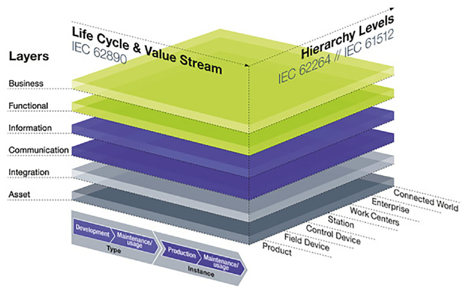
Reference Architecture Model for Industry 4.0.
Asset Administration Shell
One of the most important concepts in RAMI 4.0 are the Industry 4.0 Components which are defined as a composition between a thing (e.g. machine, field device, factory, software) and an Administration Shell. 29 As shown in Figure 2, two non-industry 4.0 components are turned into Industry 4.0 Components by adding an Administration Shell to each device and connecting the administration shells via Industry 4.0 complaint communication while maintaining traditional real-time communication between devices. This means that new capacity can be added without affecting existing functionality. In the vertical axis of RAMI 4.0, the Administration Shell includes the functional, information, and communication layer of RAMI 4.0.
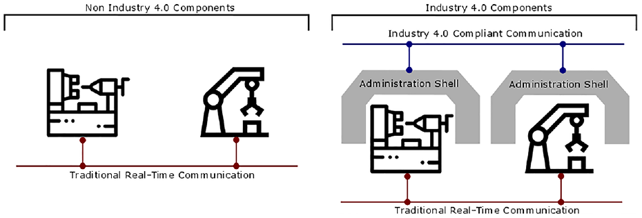
Comparison between Industry 4.0 components and non Industry 4.0 components.
The first version of the Administration Shell structure was published as a paper by the group working on the reference architectures, standards, and norms of the Platform Industry 4.0. 30 In said document, the Administration Shell is described as the virtual representation of elements, assets and objects, including software, documentation, staff, and so on. When the administration shell corresponds to the virtual representation of a physical asset, it is known as an Asset Administration Shell (AAS), which is the focus of this article.
According to this, the correct implementation of an Industry 4.0 compliant manufacturing system depends upon the correct implementation of an AAS. In other words, a set of implementation standards must be fulfilled by the information models (e.g. structured data and services). Therefore, the requirements of the AAS must be defined in detail.
Such requirements have been under development since RAMI 4.0 was revealed. First, an initial structure is presented where the AAS is divided into a Header that stores the identification of the asset and the AAS, and a Body that stores the sub-models, which virtually represent the asset 30 (see Figure 3).
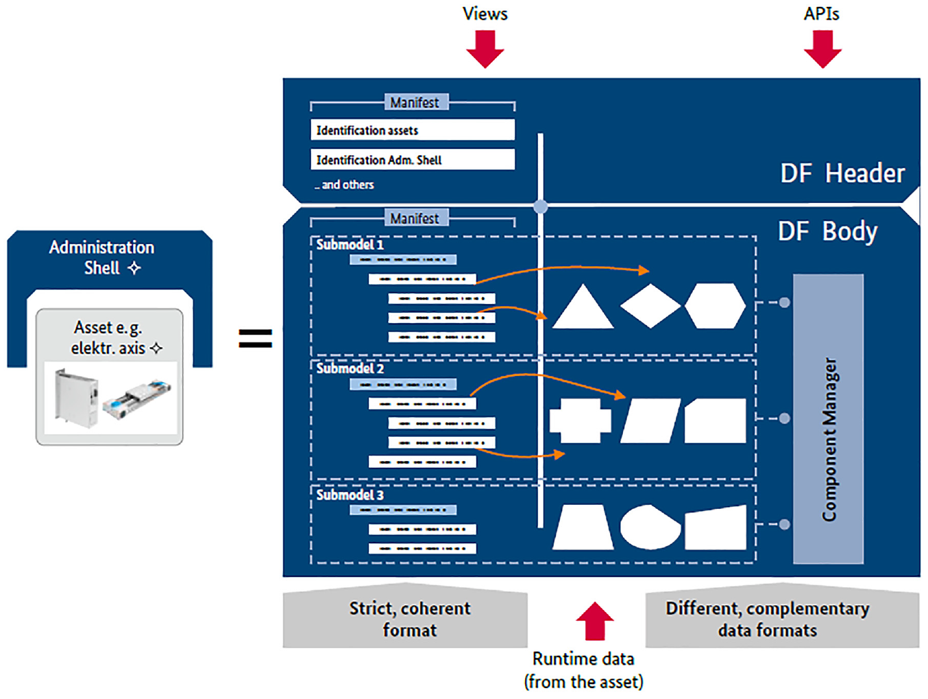
AAS structure.
In a subsequent report, a structural model wasproposed 31 (Figure 4). It is indicated that the internal composition of the AAS includes both a header and a body, while specifying the composition of the body as an integration of multiple Data Elements, the Collection of Data Elements, Views, Services, Collection of Services, and References. The relationship between these elements is also detailed as well as the standards to follow.
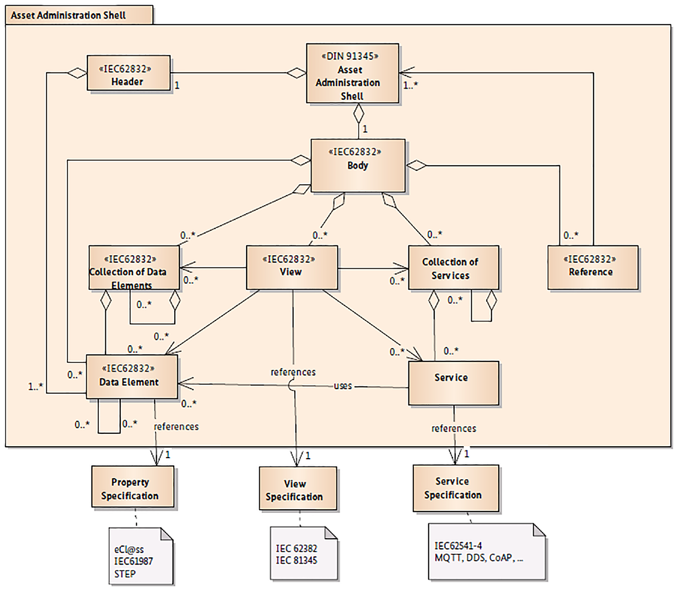
Formal structure of the AAS.
The structure in Figure 4 is generic and can be adapted to create new sub-models that integrate relevant data elements and services, depending on the device classification and its application. As previously stated, a crucial approach in Industry 4.0 is the standardization of information and services in order to achieve interoperability among manufacturing resources. It is evidenced that standardized sub-models should be used in the implementation of the AAS.
Figure 5 shows a list of several standardized sub-models that can be used in the AAS, depending upon the targeted application. For example, some models may contain a description related to safety or security for aiding operators, or a sub-model to monitor conditions and assess the state of an asset or prevent possible failures. Furthermore, Figure 6 shows how to use standardized sub-models to describe functions and define manufacturing capabilities, such as the maximum diameter of a drilling tool, or the cutting speed of a drilling process. 32
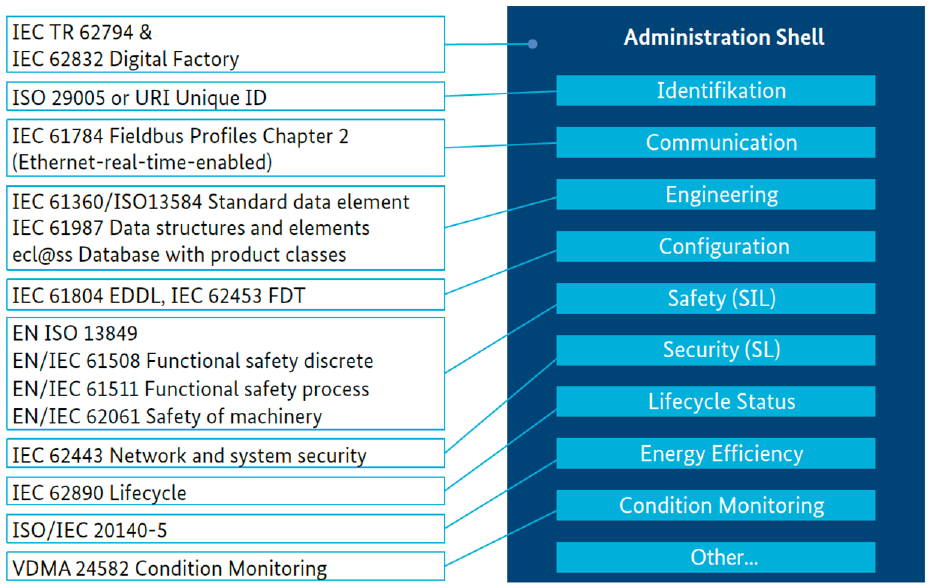
Standardized sub-models used in the AAS.
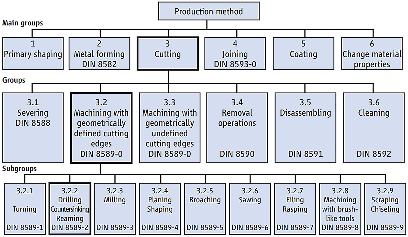
Standardized sub-models for production methods.
The models of the AAS structure shown above are technology-agnostic and should be mapped into different technological tools in order to be deployed.
OPC UA
On one hand, RAMI 4.0 establishes standard 62541 (OPC UA, Open-Standard Protocol managed by the OPC Foundation) as the approach to follow for the implementation of the communication layer, while in other reports, 31 OPC UA, MQ telemetry transport (MQTT), OpenAAS, and NAMUR module type packages (MTP) are considered as alternatives for mapping the technology of the entire AAS. In addition, an implementation example of the AAS is presented using OPC UA for the mapping of the technology. 32 Finally, a step-by-step methodology is also presented by the Mechanical Engineering Industry Association (VDMA by its acronym in German) for the migration toward Industry 4.0 based on OPC. 33
OPC UA works as a platform-independent technology for industrial communication over the transmission control protocol (TCP) protocol. Furthermore, OPC UA can run on embedded systems as well as on the internal systems of enterprises. The potential of OPC UA lies in the combination of transportation mechanisms and data modeling to provide server–client communication. The information on the server side is published using Type Instance Modeling rules and Base Modeling constructs, leading to a structured information model. This approach enables an OPC UA client to access small pieces of data without the need to understand the entire model which can be complex. 34
Type Instance data modeling of OPC UA has helped organizations to build their own models, taking the OPC information model as a basis and mapping standards such as the PLCopen, field device integration (FDI), field bus data link (FDL), and AutomationML into OPC UA. In this way, standardized communication between users and information providers can be achieved. 35
Given that these studies are official reports from Plattform Industrie 4.0, the present work considers that OPC UA should be used as the mapping technology of the AAS, which is composed of the layers of function, information and communication, from RAMI 4.0. According to VDMA, 33 an AAS can be implemented using OPC UA by following these four migration steps:
Migration Step 1: Information Access. OPC UA provides simple communication between devices by allowing access to information. The OPC device integration information model is used to expose variables provided by machines and plants. These variables can be gathered and manually subscribed.
Migration Step 2: Companion Specification. In order to increase interoperability and enable plug-and-produce applications, a standardized information model is used to describe the general characteristics and functionalities of devices, and the topologies in which they operate. Referred to as the Companion Specification, this model defines branch-specific devices and application, such as field devices, PLCs, or machines.
Migration Step 3: Extended Information Model. In addition to several companion specifications, non-standardized information models can be added. This extended version of the model includes information and functions that the developer wishes to offer explicitly in terms of experience and proprietary knowledge.
Migration Step 4: AAS. According to Figure 6, data elements and services included in the AAS should be standardized by using properties and specifications. This implies that in addition to companion specifications, standardized individual terms can also be detailed in information models. Furthermore, global identifiers (e.g. international registration data identifier (IRDI)) should be used for interoperability between Industry 4.0 components.
Demonstrative Flexible Manufacturing System
In order to provide an initial understanding of the digital retrofit process, a Demonstrative Flexible Manufacturing System (Demo FMS) was chosen to illustrate each step of the proposed methodology.
The Demo FMS is part of the Process Automation Center, which is one of the facilities of the Pontificia Universidad Javeriana in Cali, Colombia. The Demo FMS creates custom products without human intervention during manufacturing but involves the work of technicians in charge of CAD/CAM design, machine maintenance, quality control, the preparation of raw materials, and dispatch of finished products. This implies that the Demo FMS is considered an SME, since it can be used in the academic scenario for testing new technologies without inducing economic and work-related risks. Furthermore, all of the stations of the Demo FMS are more than two decades old and can only be controlled by sending commands through a serial port. Hence, this machine serves as a representative example of the current state of SMEs in developing countries. The Demo FMS (see Figure 7) is composed of five stations and a single-direction conveyor belt that moves the material from one station to the other.
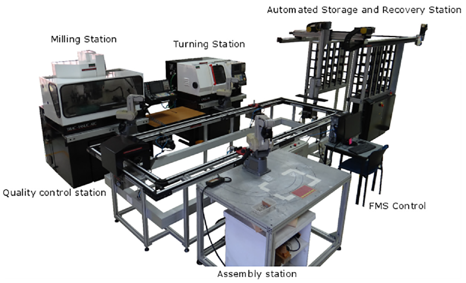
Flexible manufacturing system.
For the development of this work, only the turning station of the Demo FMS is used in the case study (see Figure 8). This station is mainly composed of two elements:
Computer numerical control (CNC) machine: A Denford two-axis CNC lathe including a Fanuc 21i-T control.
Material-handling system: A Mitsubishi Melfa RV-M1 robotic arm.
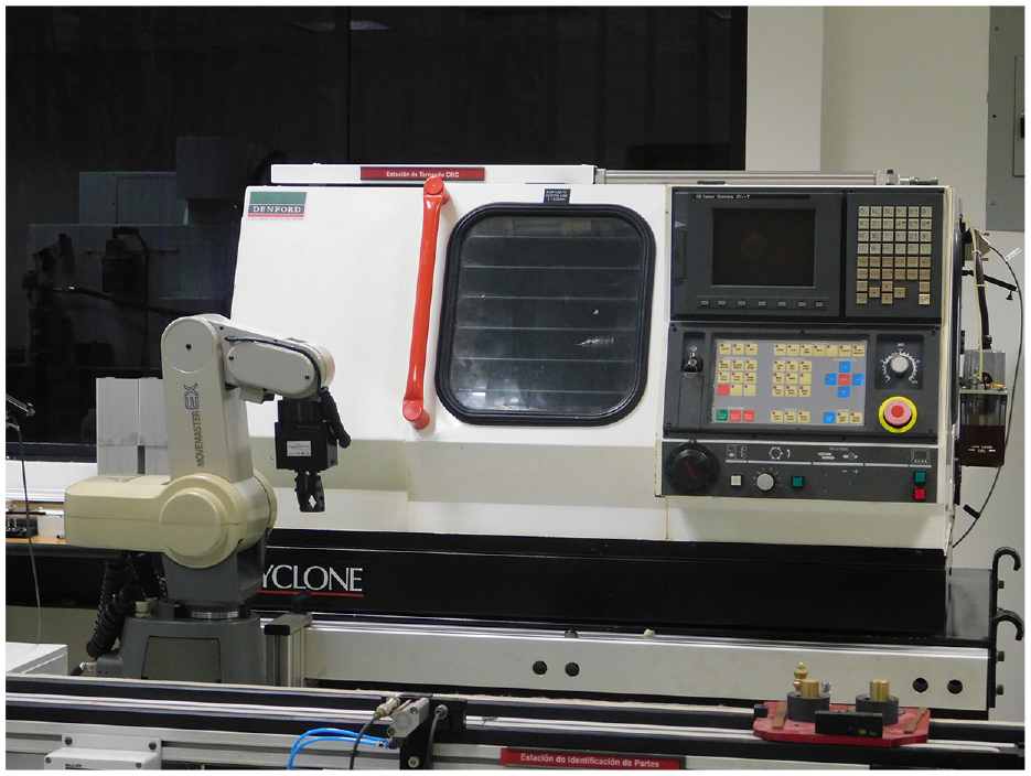
Turning station.
Digital retrofit design
There are many options for the design of a digital retrofit solution. Nonetheless, when aiming to implement a solution that complies with Industry 4.0, the digital retrofitting technique must focus on designing a proper AAS by following the necessary standards and reference models.
Digital retrofitting can be considered as a process with several procedures, which in turn are divided into a series of steps. In this section, a design procedure is proposed with the objective of developing a technology-agnostic solution that meets the requirements of Industry 4.0. Each step of the procedure is described, beginning with some general considerations and then performing the task at hand in the turning station of the flexible manufacturing system.
The design procedure starts by designing the system architecture, which includes how the assets are digitalized through the addition of the AAS. Afterward, the information technology (IT) platform is used to integrate the physical and virtual worlds according to the proposed architecture. Then, the information model for each asset is selected, and the views and references are defined.
A technology-agnostic approach for this design stage is intended to focus on understanding and specifying the particular requirements and needs of the digital retrofit method without skewing in terms of technology. The selection of technological tools is thus left for the implementation stage.
First step: define the architecture
RAMI 4.0 specifies that a single asset can have several AASs, while an AAS can nest another AAS. This means that there is more than one possible configuration for the integration of the AAS to each asset. In addition, Industry 4.0 compliant communication between each AAS should be implemented using OPC UA. According to RAMI 4.0, this is a client–server interaction, and the communication between nodes should consider the patterns shown in Figure 9.
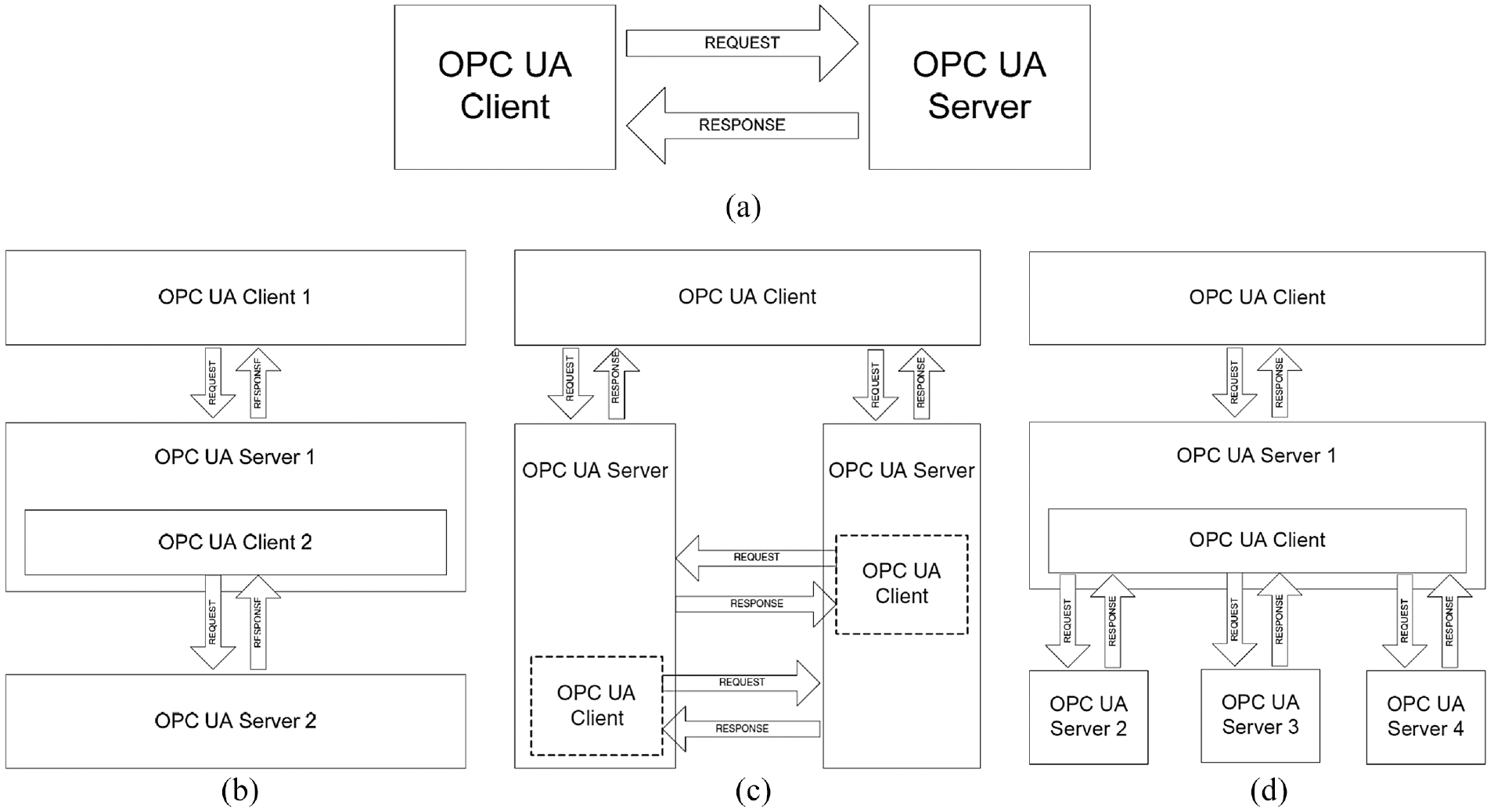
Interaction patterns for OPC UA: (a) client–server pattern, (b) chained server pattern, (c) server-to-server pattern, and (d) server aggregation pattern.
Considering the aforementioned, a design decision must be made in order to select the most relevant configuration according to the scenarios in which the manufacturing system will be used.
In Figure 10, three possible architectures are presented for the turning station. Figure 10(a) shows that each device has its own AAS and that a higher level AAS is used for the entire station. This approach is useful for plug-and-produce applications where any device can be replaced without wasting time in setting configurations. In addition, an individual AAS can be useful in distributed computation applications such as intelligent control based on multi-agent systems where the complexity of the networking increases. In the architecture shown in Figure 10(b), a single AAS is used for the entire station thus integrating the properties and services of both devices into a more complex information model yet reducing hardware requirements in terms of networking and computation. This architecture is convenient for condition monitoring in optimization or productive efficiency scenarios. The server aggregation pattern architecture in Figure 10(c) splits the virtual representation of the station into two AASs, allowing the division of properties and services according to the application and the network latency, rendering information access more efficient. 36 These examples are only three of the potential possibilities, since plenty of new architectures could be proposed depending on the targeted scenarios.
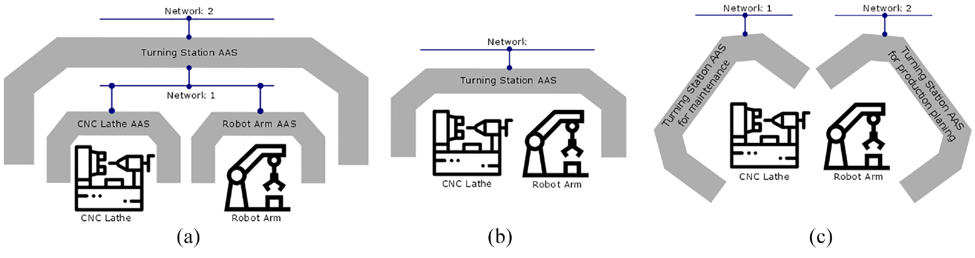
Alternatives for the AAS architecture in the turning station: (a) lathe’s AAS and robot's ASS are nested in the station's AAS, (b) a single AAS covers both lathe and robot, and (c) lathe and robot have individual AAS.
Considering the application scenario of a product-driven manufacturing application, the architecture in Figure 9(b) is selected. This architecture can be harnessed to offer the machining services of the turning station to a coordinator system seeking to meet the manufacturing requirements of a product, depending on the properties and conditions of the CNC lathe and the robotic arm. This strategy has been tested in the implementation of holonic manufacturing systems using Industry 4.0. 37 This first step leads to a model of the chosen architecture for the virtualization of the asset.
Second step: design an appropriate IT platform
In order to properly equip the manufacturing system that is being retrofitted in terms of technological resources, an appropriate IT platform must be designed to meet the communication and processing requirements of the architecture selected in the previous step.
First, the design of the IT platform involves definition of the communication networks by choosing the correct interface and network device. Considering that Industry 4.0 compliant communication is based on the TCP/IP protocol, the selection of the interface is limited to either industrial Ethernet or industrial Wi-Fi.
Next, the data storage method should be defined according to the requirements of the application scenario. For instance, relational databases could be used for structured data, non-relational databases could be used for historical real-time data, and XML files may be more suitable for the metadata of certain standardized properties.
The third task consists of defining the cyber-physical integration method that states how real-time data are mapped from the asset to the virtual world, and how the state of the asset can be modified in the virtual world. This integration can be carried out from native I/O ports of the asset or may require the addition of new digital sensors and actuators depending on the technology of the manufacturing system. Some examples of integration are as follows:
Sensors and actuators can be monitored and controlled directly using the general-purpose input/output (GPIO) ports of a Raspberry Pi board with the proper interface.
PLC memory registers can be monitored and modified from a computer using an industrial protocol through a serial port.
The functions and state of an industrial robot can be accessed from a cloud computing application deployed in a Thin Client PC connected to the robot control unit.
The fourth stage is to define the type of computer system that will be integrated to the asset. This computational system can be either physical (e.g. a single board computer) or virtual (e.g. cloud computing). Given the requirements of the communication, information and functional layers of RAMI 4.0, the communication network, the data storage strategy, and the integration previously described, the computational system should fulfill the following:
IP communication for the communication layer implementation.
Enough data storage in relational and non-relational databases for the implementation of the information layer. Note: Some micro- and nano-embedded devices just need some storage bits for the states of sensors and actuators.
Data acquisition and control through physical ports for the implementation of the integration layer. An example of this can be GPIO ports or serial communication, as well as other types of digital or analog inputs and outputs.
Information processing through software functions for the implementation of the functional layer.
Depending upon the application, these characteristics will all be necessary to a greater or lesser extent.
Finally, a model is developed to integrate all the discussed elements and is considered as the specification of the IT platform. After applying all the previous steps for the turning station, the model in Figure 11 is obtained. In this model, a desktop computer is proposed as the computational system given the need for serial ports for the integration task. A relational database is used to store variables and historical data such as the robot’s position and the operation time of the CNC lathe. Furthermore, the standard properties of the metadata are stored in XML files. Variables and properties are mapped to an OPC UA server, which uses Ethernet to communicate with other Industry 4.0 components.
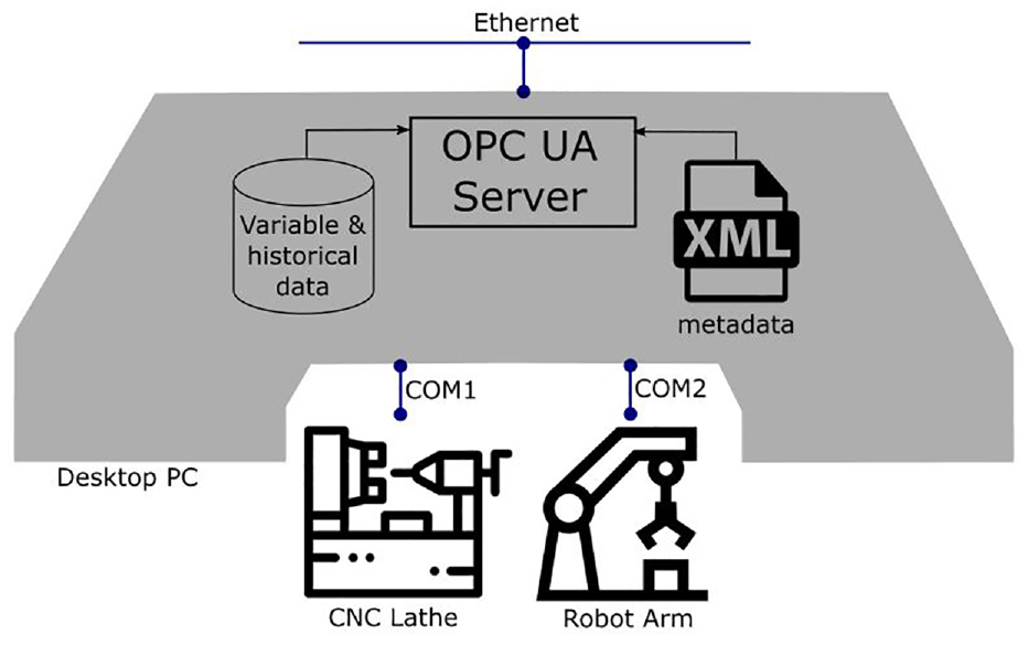
IT platform for the AAS of the turning station.
Third step: design the information model
Depending on the classification of the manufacturing system, the corresponding companion specification and extended information models should be selected. These are some examples of companion specifications:
MCS-DCS interface standardisation (MDIS) OPC UA Companion Specification for interfacing the Subsea Production Control System (SPCS) with a Master Control Station (MCS) or a Subsea Gateway to the Distributed Control System (DCS).
OPC Unified Architecture for CNC systems and for the information model of the CNC systems.
OPC Unified Architecture for field device tool (FDT) for network representation using the FDT® standard.
OPC UA PackML Companion Specification for packing machines.
It is noteworthy to mention that both the companion specifications and the extended information model are in current development, which decreases the possibility of finding a companion specification for unconventional manufacturing systems. In addition to a particular representation of the asset, some generic and standardized sub-models should be added depending on the targeted scenario. Figure 9 includes a list of some sub-models. Finally, according to the asset domain, the standardized properties of the IEC Common Data Dictionary (CDD) should be chosen from the IEC CDD repository.
The result of this stage is a table, including the sub-models and the individual properties. After applying this procedure to the turning station, Table 1 is obtained showing the chosen companion specifications for CNC systems and robots. The DIN 8589-1 sub-model is used to specify the properties of the turning process, and the VDMA 24582 field bus architecture is used to publish the state of the station.
Selected information model for the turning station.
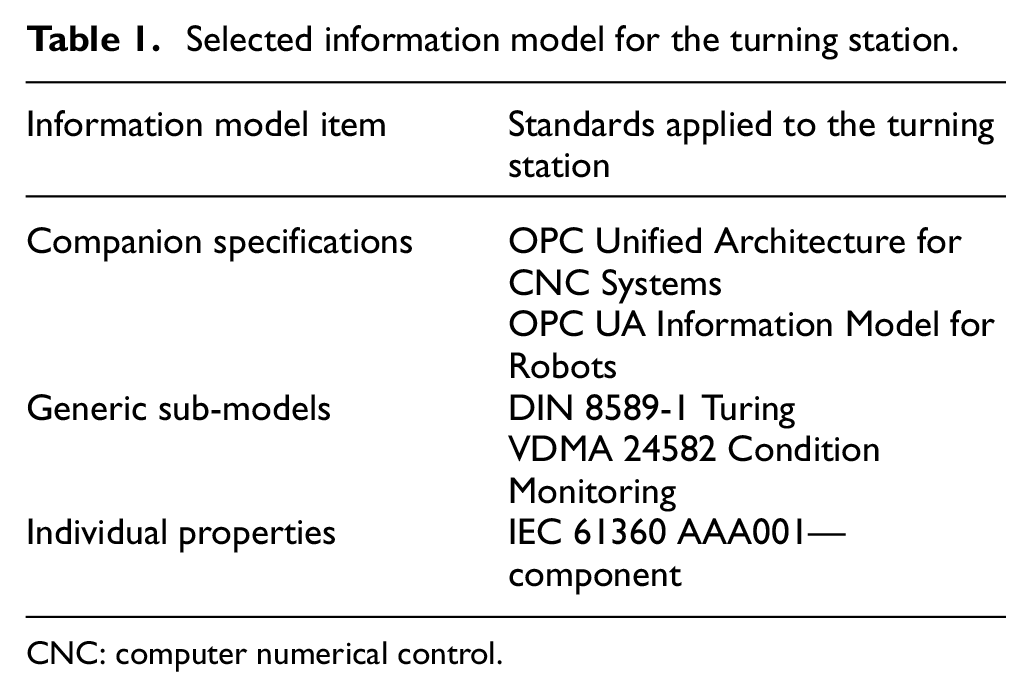
CNC: computer numerical control.
Fourth step: design views and references
Depending on the context, some views can be added to the information model, thereby facilitating access to relevant information. Views allow the automated access to some predefined properties, avoiding navigation throughout the information model and restricting access according to the credentials of the OPC UA client. For example, Figure 12 shows that View 1 has only direct access to Properties 1, 2, and 3, which could correspond to an assigned view used by the supervisory system to gain direct access to relevant properties such as production time or records from the last maintenance.
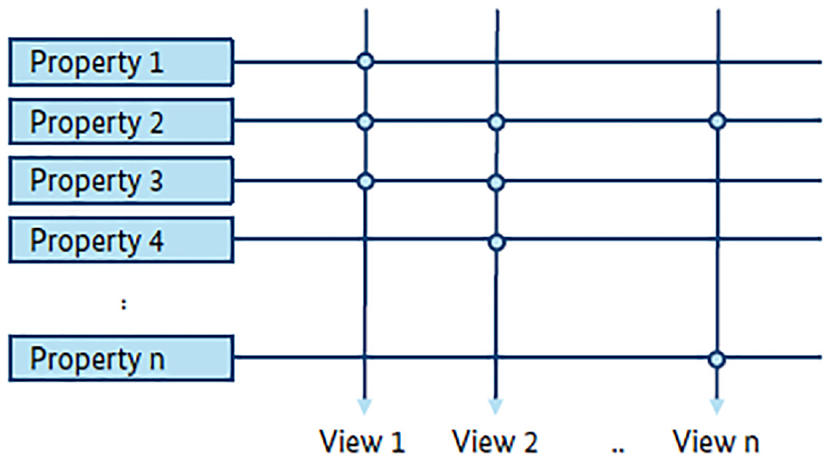
Properties linked to different views.
Apart from views, references depict information on the external connections and interactions of the AAS. These connections can refer to other assets connected to the AAS, in which segments of the plant are located and from which other assets are derived. Some common references are as follows:
Containment reference represents a hierarchical relation between two components. For instance, a machine can be contained within a station and the station can be contained within a plant.
Inheritance reference represents the properties between types. For instance, a lathe-type CNC can inherit properties from a machine-type CNC.
Type-instance reference relates to a component with the type from which it was instantiated. For example, a particular CNC lathe can be an instance of the lathe-type CNC.
For the turning station, a containment reference to the Demo FMS can be added as well as an type-instance reference to machine station type.
Design validation
A significant advantage of carrying out the design phase before any implementation procedure is the possibility to simulate the solution and validate that the capabilities of the new system do in fact correspond to the requirements of the application scenario. This validation can be achieved by using unified automation tools such as the UaExpert Client and the UaModeler in order to simulate the OPC UA communication and information model.
Digital retrofit implementation
In this section, an implementation procedure for the digital retrofit design is proposed.
First step: implementation of the IT hardware
The first step consists of the physical retrofit of the manufacturing resources. The computational system must be installed and prepared for communication with the asset through the chosen interface and to other devices in the TCP network.
The implementation of the IT hardware in the turning station is shown in Figure 13. The desktop computer of the Demo FMS control (Figure 7) is equipped with a peripheral component interconnect (PCI) serial expansion card to communicate with the CNC lathe and robotic arm. The TCP network is implemented by using a TP-Link wireless router offering 300 Mbps and creating both a local area network (LAN), where all the AASs of the Demo FMS are connected, and a WLAN, where an external AAS can be integrated through the Internet.
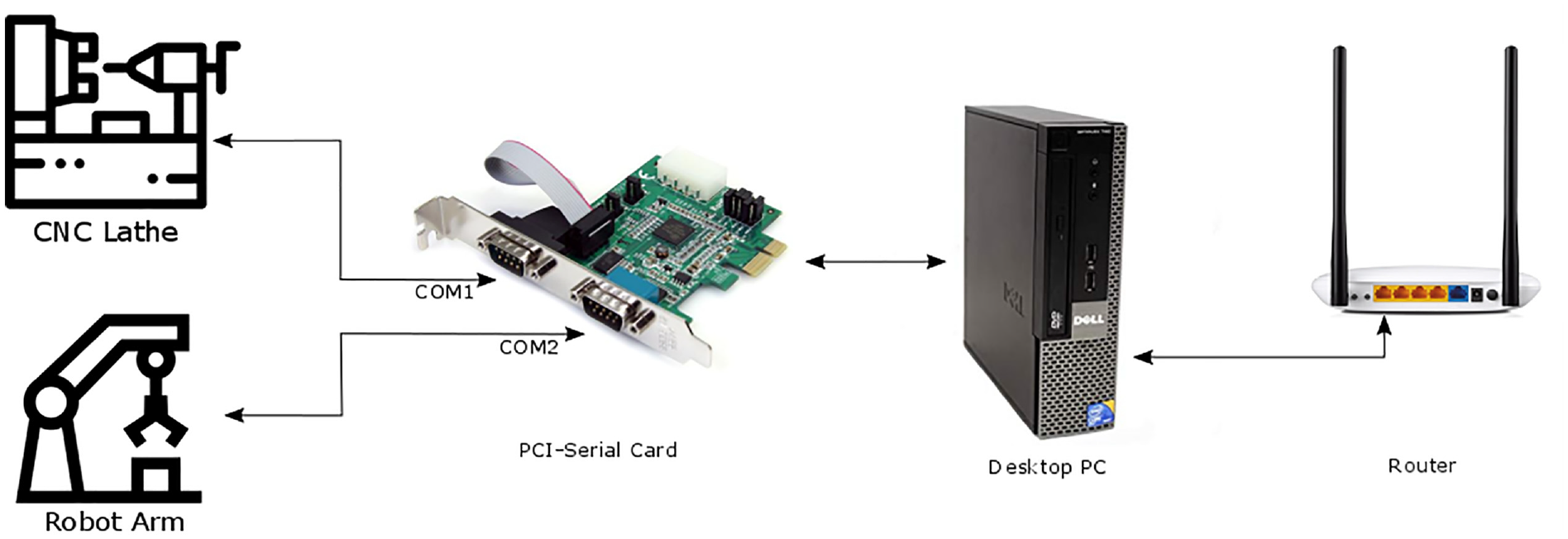
IT hardware implemented for the turning station.
Second step: implement the data storage and internal services
According to the designed information model, the values of each of the variables and properties should be assigned and stored in the memory of the computational system according to the model of the IT platform, mapping the designed models to appropriate technologies.
The information models are composed by data and metadata such as variables, properties, functions, and objects. The value of the variables and properties may be stored in databases, either related or non-related depending on their nature, for example, structured data as the hierarchy or the architecture of the communication can be stored and referenced in related databases such as MySQL and PostgreSQL. On the contrary, large amounts of data such as the historical sampling of variables should be stored in non-relational databases. (e.g. MongoDB, Cassandra). In addition, XML files can be used to store static metadata with standard structures.
Functional elements such as services, functions, or methods must be implemented within information models, serving as functional blocks derived from proper programming languages, which permit the usage of interfaces for data acquisition and control allowing interaction with the asset.
Third step: establish simple communication through OPC UA
In this phase, OPC UA servers and clients are deployed on the computational system, allowing resources such as machines, robots, or people to browse, read, write, or call methods and to subscribe using a generic information model such as the OPC UA Device Integration.
Available mapping implementations for OPC UA
Nowadays, there are several options for the implementation of OPC UA servers and clients. The OPC Foundation offers three stacks: one implemented in C#, one in ANSI C, and a third option in JAVA. In addition, there are various commercial implementations freely available online, where FreeOpcUa (C++ and Python) and Open62541 (C and C++) stand out as open source implementations. Unified Automation (C++ and Java) and Prosys (Java) are commercial solutions.
In the example of the turning station, the FreeOpcUa implementation is used to deploy the OPC UA server in the AAS. It was chosen considering that the Python programming language reduces development times, as well as facilitates the integration with databases and functions carried out in the previous step. The OPC Device Integration information model can easily be implemented using the functions included in the XML importer from FreeOpcUa.
At this point, it is recommended to test the basic OPC UA services like Browse() or MethodCall() before moving on with the next step.
Fourth step: populate OPC UA servers with information models
In this step, the data corresponding to the values of the information models that were previously stored in the computer must be linked to the address field of the OPC UA server. This is achieved with the help of tools and libraries included in the implementation programming languages of the OPC UA servers such as Python, Java, C, C#, and C++, which offer functions to interact with information systems and variables in real time. Some of these functions include relational and non-relational database connectors, XML parsers, serial communication, and read and write Excel files, among other tools.
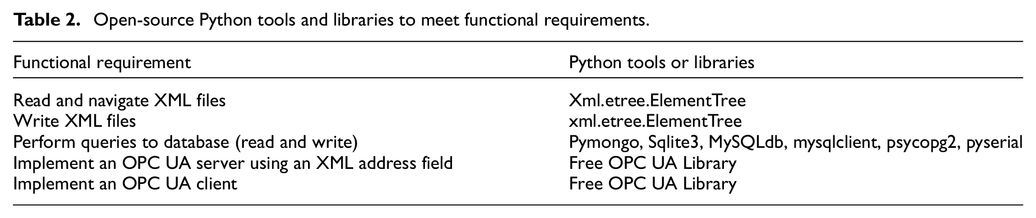
In this scenario, the services implemented as Python functions are mapped to OPC UA methods with the add_method function from FreeOpcUa. All the required libraries and tools are presented in Table 2.
Open-source Python tools and libraries to meet functional requirements.
In Figure 14, the software composition and structure established through a UML component diagram are presented taking the OPC UA server as the main component, which provides services such as view, call, browse, and other methods. Thus, clients are allowed to access data in the information model with a more detailed description of the information exchange services discussed in Mahnke et al. 35 Another component is the updater and its “write” function which keeps up-to-date figures of the model variables according to the data obtained from the XML parser and the database manager. Moreover, the “function loader” component provides access to the functions with the use of “threads” to the server. Finally, in order to create standardized information models, XML models are used for the OPC UA server.
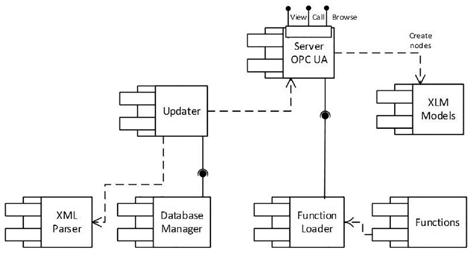
UML component diagram of the developed application.
Figure 15 displays the AAS software model in the form of a class diagram. In this model, the AAS class is comprised of at least one instance of the class server, which is needed to deploy the server. An alternative can include one or more instances of the OPC UA client class in order to actively interact with other AAS. One instance of the run class (or even none) may be required to activate the AAS function. One instance of the database client grants access to databases when information needs to be updated in the OPC UA server.
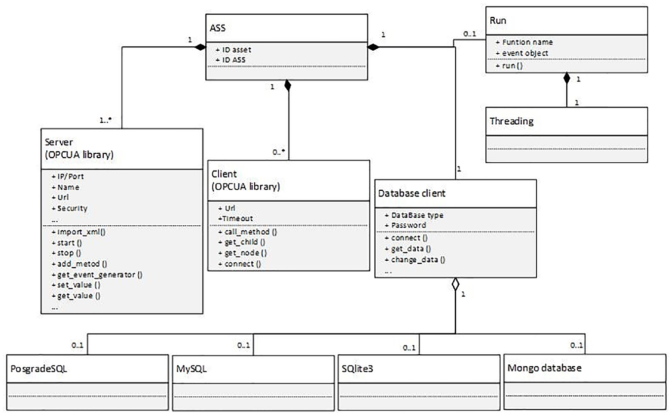
UML diagram of the classes used in the developed application.
The result of this procedure is a manufacturing system, which in this case is a turning station. The system can be integrated to an Industry 4.0 network to be used in applications that require data and services from the OPC UA server. In comparison to the initial state of the system, the data and services from the turning station can now be accessed online via a standardized platform. This enables any Industry 4.0 application to harness resources and make automatic decisions through artificial intelligence or even analyze real-time information by integrating the system to a Big Data application. A product-driven manufacturing application is the first example of an integration-based retrofitted system in which the parameters and services of both the robot and the CNC lathe are configured according to any product needs.
Summary
The proposed methodology is summarized in the flowchart of Figure 16. In this representation, the deployment relations between the digital retrofit design and the implementation are shown, as well as the mapping relationship between the data and services to the OPC UA information model.
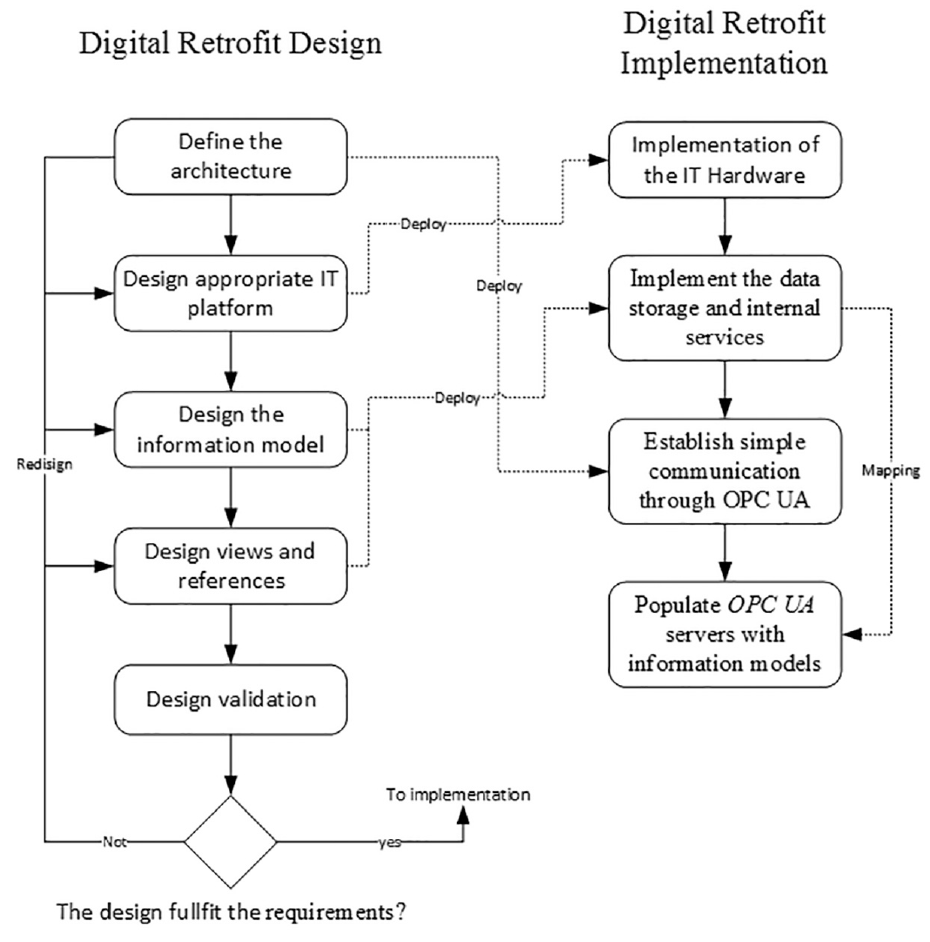
Digital retrofit methodology flowchart.
Conclusion
Considering the importance of SMEs for the economic growth of the country, it is paramount to foster their competitiveness in global markets. In response to this scenario, this article described a methodology for the adoption of the Industry 4.0 paradigm in SMEs through digital retrofitting by systematically designing and implementing the proper IT infrastructure, using technological tools for easy access. As a result, this methodology was applied to the Demo FMS, building an experimental case of an SME where new application examples can be implemented, tested, and evaluated. This approach will facilitate the future implementation of Industry 4.0 information and communication technology infrastructure in SMEs by following a validated procedure.
The digital retrofitting technique applied in the Demo FMS showed a reduction in terms of migration (to Industry 4.0) costs compared to an entire revamping of the equipment. For the case study, the final implementation costs are estimated as a single investment of US$800 in technological development and US$200 in hardware for each component that needs to be upgraded. This represents 5% of the acquisition costs for commercial solutions such as the Fanuc Focas Ethernet Driver (e.g. driver for CNC equipment update) and the Universal Robot UR3 (Industry 4.0 robot).
In addition to savings in investment costs, the implementation of an information and communication technology infrastructure that complies with Industry 4.0 through digital retrofitting offers new opportunities in Industry 4.0 application scenarios, 38 where available data and services are required in predictive maintenance, quality control, decentralized control, adaptive logistics, and product-driven manufacturing. The implementation of these scenarios will be considered in future work.
It was evidenced that the methodology proposed in this article requires monotonous and repetitive tasks from the developer such as the one-way binding of the databases with their respective variables in the OPC UA information model. Hence, future work involves the design of a framework that facilitates the development and deployment of the information and communication technology capacities taken from Industry 4.0.
Footnotes
Acknowledgements
The authors would like to thank Universidad del Valle for funding this project and the Process Automation Center in Pontificia Universidad Javeriana Cali for giving access to the Demonstrative Flexible Manufacturing System (Demo FMS) machine.
Declaration of conflicting interests
The author(s) declared no potential conflicts of interest with respect to the research, authorship, and/or publication of this article.
Funding
The author(s) disclosed receipt of the following financial support for the research, authorship, and/or publication of this article: This study was funded by the Universidad del Valle.