
Abstract
Engineering ceramics are increasingly extensively applied in the aerospace, vehicle, armor protection and other fields due to their excellent performances such as high compression strength, high hardness, low density and high protection performance. However, engineering ceramics are typical difficult-to-machine materials, especially in the hole machining under constant feed rate, which limits the promotion and application. In this study, by combining a specially developed novel thin-wall diamond trepanning bit with a low-frequency axial vibration machining, the hole machining process for the constant feed rate of Al2O3 engineering ceramics was experimentally studied and the influence of the low-frequency axial vibration process on the axial drilling force, hole-wall surface roughness and edge chipping size of holes machined was analyzed. The results showed that the low-frequency axial vibration machining obtained a lower axial drilling force and a smaller edge chipping size compared to the traditional drilling process. Moreover, both the axial drilling force and the edge chipping size declined markedly with the rise in amplitude. However, the hole-wall surface roughness presented a rising trend due to the hammering effect of vibration. The process technology proposed in this article realizes the hole machining for a constant feed rate of Al2O3 engineering ceramics and provides a reference for the engineering lot-size hole machining of engineering ceramics.
Keywords
Introduction
Engineering ceramics are characterized by excellent performances such as high compression strength, high hardness, low density and high protection performance and are increasingly extensively applied in the aerospace, vehicle, armor protection and other fields. 1 Assembling with other parts usually requires that engineering ceramic components undergo secondary hole machining. At present, the special micro-hole machining methods available for engineering ceramics include laser machining,2,3 ultrasonic machining4,5 and electrical discharge machining (EDM).6,7 However, they have several shortcomings such as low machining efficiency and high cost. Laser microfabrication experiments on glass, silicon and ceramics by Rihakova and Chmelickova 2 disclosed that the ultrafast laser can achieve better processing quality. Hanon et al. 3 used millisecond pulsed Nd:YAG laser to drill alumina ceramics with thickness of 5 and 10.5 mm, respectively. Combined with finite element analysis, the effects of laser peak power, pulse duration, repetition rate and focal plane position on processing quality were explored. Nath et al. 4 carried out ultrasonic drilling of silicon carbide, zirconia and alumina ceramics and studied the effect of microcracks on the quality of micromachining (entrance chipping, wall roughness and subsurface damage). Ramulu 5 used Al2O3, B4C and SiC abrasives to machine SiC ceramics and TiB2/SiC composites by ultrasound, respectively. The effects of different abrasive grit sizes (120, 220 and 400) on material removal rate, surface integrity and flexural strength were presented. The effects of EDM parameters (pulse on-time, pulse off-time and peak current) and electrical resistivity on EDM performance of ZnO/Al2O3 ceramics were studied by Ji et al. 6 The results showed that the electrical resistivity of ZnO/Al2O3 ceramics, which could be effectively machined by EDM, increased with the increase in pulse on-time and peak current and with the decrease in pulse off-time.
In the large hole machining of engineering ceramics, diamond trepanning bits are mainly used for grinding holes.8–13 Gao and Yuan 8 used impregnated diamond bits to carry out constant pressure feed drilling experiments on Al2O3 armor ceramics and determined the optimum matrix formula suitable for armor ceramics. Zheng and colleagues9–11 experimentally investigated drilling efficiency, hole quality, failure mechanism and wear loss of impregnated diamond bits when machining armor ceramics. Zhang et al. 12 conducted a comparative study on core drilling of silicon carbide and alumina engineering ceramics with mono-layer brazed diamond bits, studied the influence of coolant type and diamond grit concentration on drilling efficiency and discussed the surface morphology of ceramics. A new theoretical model of material removal rate was proposed by Zhang et al. 13 It was found that the material removal rate increased with the increase in static load, speed of drilling tool and particle size of abrasive. Singh and Singhal 14 carried out an experimental study on rotary ultrasonic machining of Macor ceramics using diamond core drill. The impact of process factors such as feed rate, spindle speed, ultrasonic power and coolant pressure on machining characteristics had been explored. Usually, to prevent the excessive drilling force from producing ceramic chipping and subsurface cracks, a constant pressure feed or small feed method is generally adopted; however, its application is restricted by the uncertain machining duration, low efficiency and unsatisfactory drilling quality of entrance and exit.
Low-frequency axial vibration (LFAV) drilling is a novel hole drilling technology. A controllable axial reciprocating motion can be produced between the bit and workpiece through a vibration device, which conducts low-frequency pulsed drilling machining on the unmachined surface. Ladonne et al.15,16 carried out vibration-assisted drilling experiments on aluminum. The kinematic model of the machining process was optimized by introducing two new operating parameters, amplitude and frequency. Li et al. 17 illustrated the development of a vibration-assisted device that differs from those possessing stationary vibration modes and carried out a series of experiments in micro-milling 6061 aluminum alloy to show the effectiveness of the developed device in improving surface integrity and quality. According to the experimental results, the machining parameters were optimized. On the whole, the LFAV process can effectively improve chip breaking and removal conditions, reduce average friction in the machining area and thus reduce the axial drilling force and edge chipping size. It also makes it convenient to guide coolant into the machining area, which facilitates to achieve better cooling effect, slow down bit wear and accordingly improve machining quality and efficiency.
Taking Al2O3 engineering ceramics as the machining object, this study combined a specially developed novel thin-wall diamond trepanning bit with the LFAV process, for an intensively experimental study on the hole machining under a constant feed rate. And the influence of the LFAV process on the axial drilling force, hole-wall surface roughness and edge chipping of holes was analyzed. Results obtained from the study laid the foundation for the application and promotion of the LFAV machining process in the lot-size machining of engineering ceramics.
Kinematic characteristics of LFAV machining
When drilling under LFAV machining, there are three kinds of motions, including the axial feed, rotation of the spindle and relative axial harmonic vibration between the drill bit and the workpiece. According to the kinematic analysis to LFAV machining, the displacement of any single abrasive grit on the bit end face in the axial direction can be expressed as

where t is the time (s), n is the spindle speed (r/s), fr is the feed per revolution (mm/r), A is the amplitude (mm) and f is the frequency (Hz).
During the LFAV drilling process, the circumferential angular displacement of the drill bit is θ = 2πnt, where t = θ/(2πn), which can then be substituted into equation (1) to get
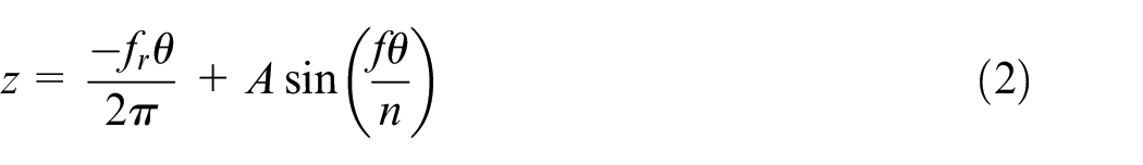
Therefore, the kinematic trajectory equation of any single abrasive grit can be expressed as
where wf = f/n is the frequency conversion ratio; x, y and z represent the position of any single abrasive grit in the bit column coordinate system; plane xy is the machining plane; and r represents the vertical distance of any abrasive grit to the bit center line.
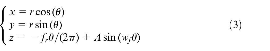
Figure 1 shows the schematic diagram of the movement path of single abrasive on the bit end face. The bit is driven with a sinusoidal downward feed. According to equation (1), the acceleration

When t = 2πm + 3π/2 (m = 1, 2, 3, …),
Trajectory of single abrasive grit under LFAV machining.
According to Newton’s second law of motion, during the process of LFAV machining, the instantaneous inertial force is the highest at the lowest point, that is, the abrasive grit generates a large instantaneous impact force on the machined surface, which causes cracks on the workpiece surface, and reduces the difficulty of removing material and the cutting force. Meanwhile, the periodically varying gap between the bit end face and the machined surface would facilitate the entry of coolant into the grinding zone and take away the cutting heat and powdered ceramic chips quickly. Therefore, compared with conventional machining, LFAV machining helps to reduce the difficulty of drilling engineering ceramics, slow the bit wear rate and thus maintain the favorable processing performance of the bit.
Experimental design
Novel thin-wall diamond trepanning bit
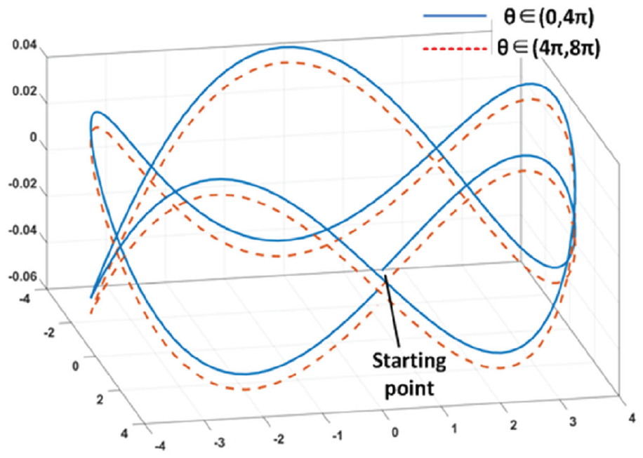
Experimental testing was performed using the novel thin-wall diamond trepanning bit (Figure 2) prepared by a composite process of sintering and brazing, and the bit handle material used was 40Cr steel. The sintering materials used for the bit working region (Figure 3) mainly consisted of Co powder (28%–32%), Ni powder (18%–22%), Cu powder (17%–20%) and small quantities of Mn powder and Al powder (2%–3% in total). The brazing alloy was a combination of Cu-based brazing alloy (12%–15%) and Ni-based brazing alloy (15%–20%).
Novel thin-wall diamond trepanning bit.
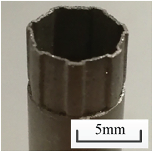
Bit working region structure.
The thin-wall diamond trepanning bits were 8 mm in outer diameter, and its working region was designed in a wavy tooth shape (Figure 3), with a wall thickness of 0.4 ± 0.1 mm, while the diamond grits had a grade of SMD (diamond grains for metal bond saw; grain sizes: 70/80, 80/100 and 100/120; quantity mixing ratio: 1:1:1) and a concentration of 150%.
The bit preparation process is as follows: First, all the materials (diamond grits, sintering powder and brazing alloy powder) were fully mixed and then were loaded into a graphite die for cold press molding along with the 40Cr steel handle. After sintering under pressure at 680–720 °C for about 15 min, the bit was transferred to a vacuum brazing furnace with a degree of vacuum in excess of 3 × 10⁻³ Pa, brazed at 920 °C for 10 min. Thus, the Ni-based brazing alloy could react with the diamond and combine with each other. Finally, after natural cooling to room temperature, the bit was taken out of the die. Then, the working part of the drill bit is polished and trimmed, and the base part of the 40Cr steel material can be precisely trimmed, in which the coaxiality error of the product is required to be no greater than 0.05 mm. Finally, the entire product surface is nickel-plated and rust-proofed.
This composite process of hot pressing sintering and high temperature brazing could guarantee high concentration of the diamond grits and sufficient bonding strength between the matrix and the diamond abrasive, endowing the bit with excellent sharpness and self-sharpening performance, and thus reducing the cutting force and extending its service life. During the hole machining process, the sharpness of the drill bit is mainly ensured by a periodic layer change of the diamond abrasive material in the working part, so that sharpening is not required during processing.
Experimental conditions and parameters
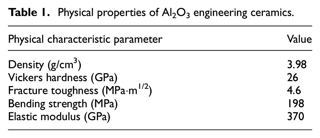
The workpiece material was Al2O3 engineering ceramics (Al2O3 content: 99.5%; thickness: 8 mm). The physical properties of the Al2O3 engineering ceramics are listed in Table 1.
Physical properties of Al2O3 engineering ceramics.
As shown in Figure 4, this study was carried out on a Hanchuan XH715D Vertical Machining Center (spindle speed range: 60–8000 r/min; maximum spindle power: 11 kW; maximum spindle output torque: 70.3 N·m). The LFAV device was the PG8040 mechanical LFAV cutter holder (Figure 5) manufactured by Mitis (France). It had a maximum adjustable amplitude of 0.25 mm, maximum speed of 3500 r/min, tolerable axial force of 4000 N, vibration frequency of 2.5 times per cycle and allowable torque of 20 N·m. Conventional cutting emulsion fluid was used for cooling. The ceramic workpiece was clamped by a vice and mounted on the machine worktable.
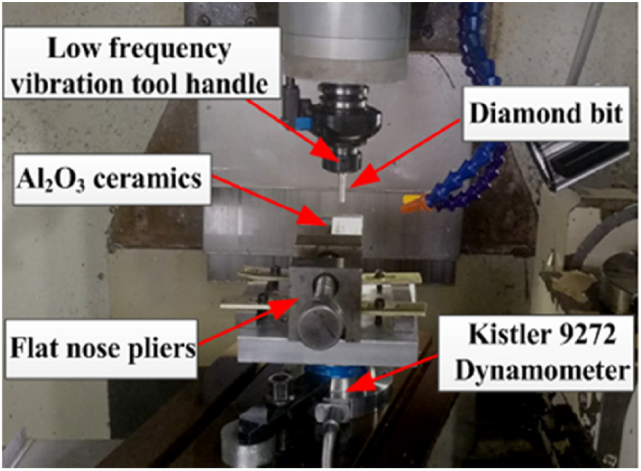
Physical picture of the experimental machining setup.
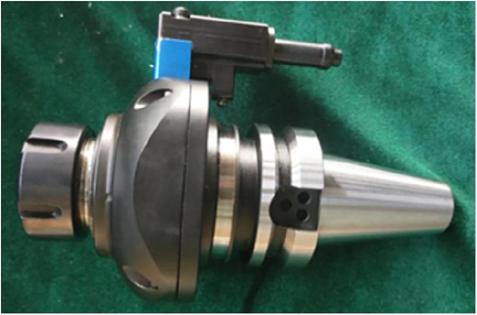
PG8040 vibration cutter holder.
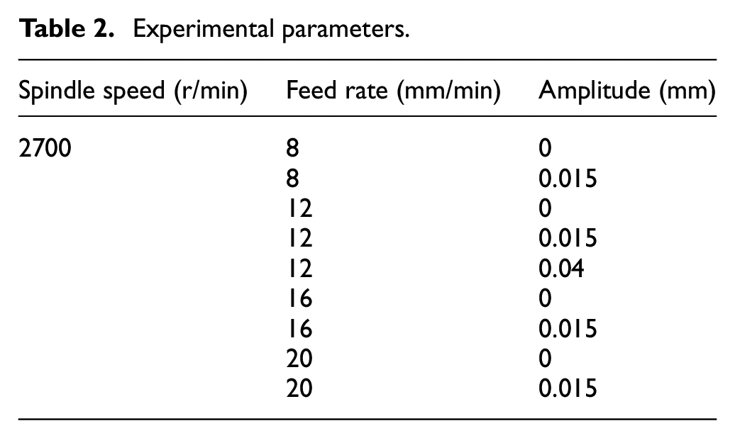
The spindle speed used was 2700 r/min, and the vibration frequency was kept constant during machining. The single-factor method of feed rate and amplitude was adopted for test design (feed rate: four levels; amplitude: two levels). To analyze the influence of amplitude on the process effect, an additional group of machining parameters was designed: feed rate: 12 mm/min; amplitude: 0.04 mm. The specific experimental parameters are summarized in Table 2.
Experimental parameters.
Axial force was measured using a KISTLER 9129AA compact multi-component. The profile arithmetic average deviation, Ra, was selected as the evaluation parameter for the hole-wall surface roughness and measured using a TR200 roughness tester. The edge chipping size was measured using a VK-X100 laser scanning microscope.
Experiment results and analysis
Machining method for constant feed rate
The essence of hole machining by the diamond trepanning bit is the process of grinding the workpiece material with the diamond grits on the end face of the bit. Currently, the constant pressure feed or small feed method is widely adopted for the hole machining of engineering ceramics and other hard and brittle materials.8–13 The main shortage of the above method is uncertain machining duration and low efficiency. This study combined the novel thin-wall diamond trepanning bit and the LFAV process to realize machining Al2O3 engineering ceramics under a constant feed rate. Remarkably, automatic blanking also could be realized basically, namely without dismantling the bit for taking out the nesting after hole machining. Under experimental conditions, during the conventional machining, the nesting frequently got stuck on the inner wall of the trepanning bit, namely not falling off automatically (Figure 6(a)), and the automatic blanking ratio was only about 71.4%. After taking out the nesting manually by stopping the machine, it could be seen that the inner wall of the bit was bonded with thick ceramic debris (Figure 6(b)). In contrast, when drilling with the LFAV process, the automatic blanking ratio was approximately 100%, and there was much less ceramic debris bonded on the inner wall of the bit (Figure 6(c)).
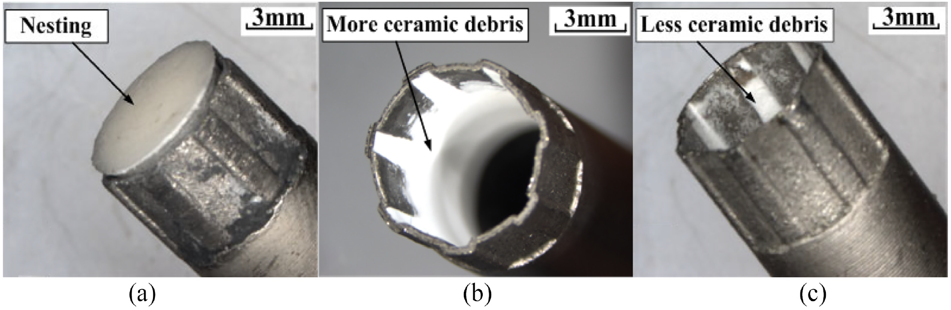
Used bits: (a) nesting stuck, (b) after nesting taken out and (c) automatic blanking.
This can be explained based on the following aspects from the bit and LFAV process. First, the specially developed diamond trepanning bit has a high concentration (150%) for diamond grits and sufficient bonding strength between the matrix and diamond abrasive, which endows the bit with excellent sharpness to reduce the cutting force. Second, the working region of the tool was designed in a wavy tooth shape, with a wall thickness of 0.4 ± 0.1 mm. Such a design, on one hand, facilitates the discharge of powdered ceramic chips, reduction of average friction in the machining area and timely introduction of coolant into the machining area. On the other hand, the thin wall could directly reduce the removal quantity of workpiece material and significantly reduce the axial drilling force. Third, the SMD-grade diamond grit selected was characterized by perfect crystal, high toughness and other advantages and is ideal for the machining of engineering ceramics. Diamond grit sizes selected were 70/80, 80/100 and 100/120, mixed in a quantity ratio of 1:1:1. With the wear of the bit, diamond grits were successively ground and worn down according to particle sizes, which effectively made up for the deficiencies of excessive bonding strength and poor self-sharpening performance due to the brazing process. Finally, according to the Kinematic characteristics of LFAV machining, the instantaneous impact force under LFAV machining facilitates cracks producing and propagating in the workpiece and reduces the drilling force. Moreover, the periodically varying gap between the bit end face and the machined surface facilitates the entry of coolant into the grinding zone, and thus the cutting heat and powdered ceramic chips could be flushed out in time to avoid drill burn, slipping and many other defects.
Axial drilling force
The axial drilling force constitutes an important factor that influences hole machining quality. During the process of machining Al2O3 engineering ceramics using the thin-wall diamond trepanning bit, the data on the axial drilling force were obtained by solving the average value in the stable machining stage (the middle 1/3 of the whole machining process). Figure 7 shows the changes in axial drilling force with feed rate under traditional machining and LFAV machining (amplitude = 0.015 mm). According to the results of the analysis, with the increase in feed rate, the axial drilling force rose gradually, mainly because the increase in feed rate increased both the machining depth per unit time and the cutting thickness of single diamond grit on the bit. Thus, the axial drilling force was increased as well.
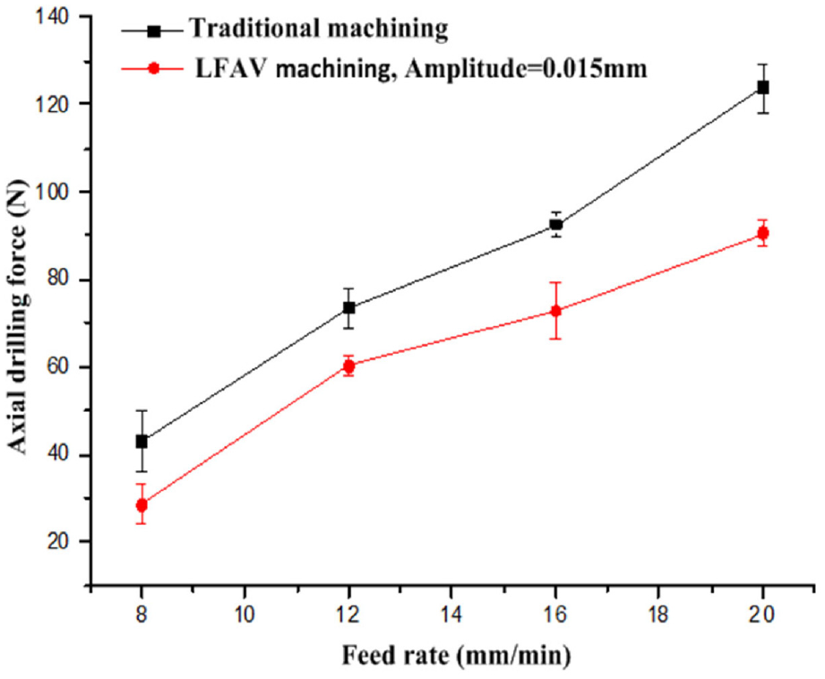
Influence of feed rate on axial drilling force (spindle speed = 2700 r/min).
As can be known from Figure 7, at the same feed rate, LFAV machining could acquire a lower axial drilling force, with a falling range of 20%–30%. This was because, in the process of LFAV machining, there was periodic contact and separation between the bit and the workpiece surface, which caused the cutting trajectories of diamond grits to intertwine with each other. Thus it became easier for the surface cracks on engineering ceramics to propagate and penetrate.18,19 This leaded to easier material removal, which was macroscopically manifested by the reduction of drilling axial force in the machining process. Furthermore, LFAV machining facilitated the guidance of the emulsion fluid into the machining area. It could effectively improve cooling and chip removal conditions, avoid the carbonization of diamond grits caused by the accumulation of cutting heat and thus enhance the cutting performance of the diamond bit and reduce the axial drilling force.
Figure 8 shows the change in axial drilling force with amplitude. It can be seen that the axial drilling force declined markedly as the amplitude rose. According to the fracture mechanics model of hard and brittle materials,20–22 when the vibration amplitude reached a certain extent, the load on the workpiece would exceed the limit load and subsequently the cracks could be produced. With the further increase in vibration amplitude, the brittle removal would be the main material removal mode of ceramic workpiece. At the same time, under the hammering effect of vibration, cracks were more likely to occur and propagate,18,19 which reduced the axial drilling force.
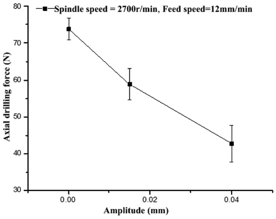
Influence of amplitude on axial drilling force.
Hole-wall surface roughness
Hole-wall surface roughness directly reflects the surface morphology of the hole machined by the diamond trepanning bit. In this study, the profile arithmetic average deviation, Ra, was selected as the evaluation parameter of the hole-wall surface roughness. To avoid excessive fluctuations and unrepresentativeness of test data, five surface roughness values were randomly selected from each hole wall to calculate their trimmed mean, thus obtaining the data on hole-wall surface roughness. Figure 9 shows the change in hole-wall surface roughness with feed rate for a spindle speed of 2700 r/min under traditional machining and LFAV machining (amplitude = 0.015 mm).
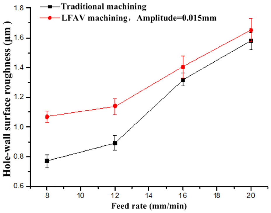
Influence of feed rate on surface roughness Ra (spindle speed = 2700 r/min).
As can be known from Figure 9, with the increase in feed rate, the hole-wall surface roughness increased under both machining methods. When the feed rate is low, LFAV machining obtained a higher hole-wall surface roughness. With the increase in feed rate, the gap in surface roughness between the two machining methods declined rapidly. The increase in feed rate increased the machining depth per unit time, caused the cutting trajectories of diamond grits to be sparse, and increased the chips produced per unit time. Consequently, the chip removal became more difficult and the hole-wall roughness increased. When the feed rate was low, due to the hammering effect of LFAV machining, cracks were easily generated on the machined surface,18,19 thus increasing the hole-wall surface roughness. With the further increase in feed rate, the hammering effect became less significant and thus the gap in surface roughness between the two machining methods declined.
Figure 10 shows the variation in hole-wall surface roughness with amplitude. According to the analysis, with the rise of amplitude, the hole-wall surface roughness presented an obvious rising trend. 23 This was because the increase in the amplitude of LFAV machining caused the hammering effect of vibration to be more significant and accordingly the generation and propagation of cracks would be more serious, which directly increased the hole-wall surface roughness. To obtain a smaller hole-wall surface roughness, the secondary machining with a lower feed rate could be carried out during the bit return process.
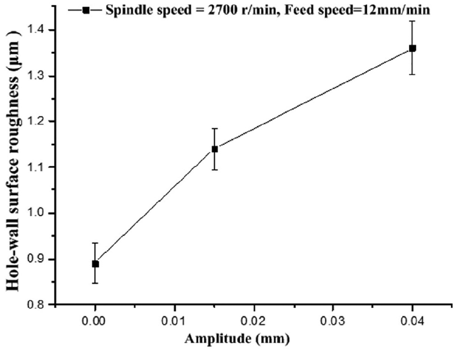
Influence of amplitude on surface roughness Ra.
Edge chipping size
Al2O3 engineering ceramics has a low fracture toughness and is high sensitive to cracks. In the hole machining process, it is extremely susceptible to chipping at the hole entrance and exit.21,24,25 Generally, the edge chipping size at the exit is far larger than that at the entrance. Figure 11 shows the exit edge chipping of Al2O3 engineering ceramics with 8 mm holes drilled.
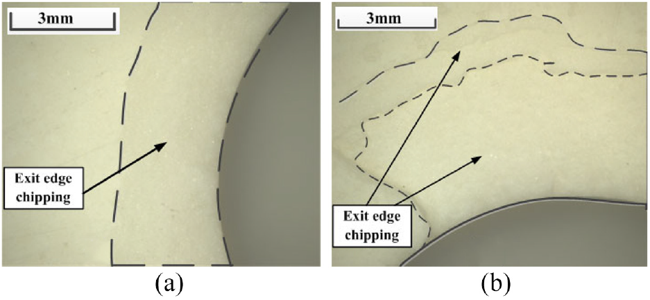
Exit edge chipping: (a) feed rate = 8 mm/min and(b) feed rate = 16 mm/min.
In this study, the maximum exit edge chipping size L (Figure 12) was selected as the index for evaluating the hole machining exit quality of Al2O3 engineering ceramics. L can be expressed as

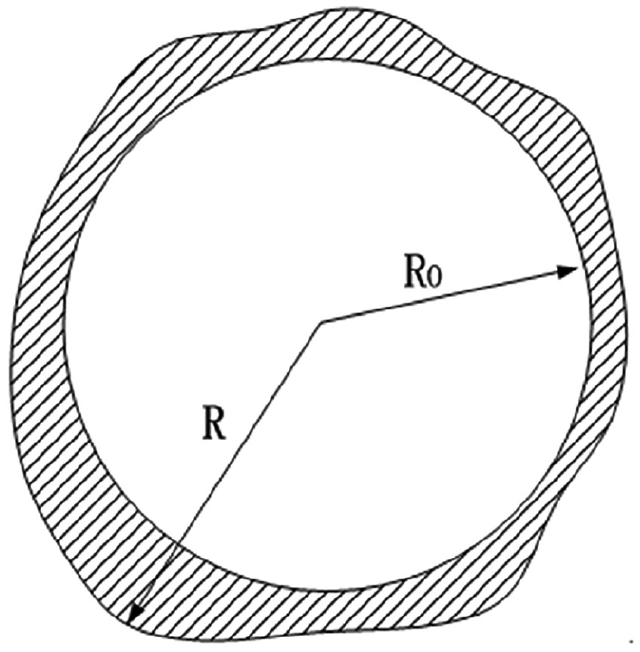
Schematic diagram of exit edge chipping.
Figure 13 shows the change in maximum chipping size with feed rate under traditional machining and LFAV machining (amplitude = 0.015 mm). According to the analysis, with the increase in feed rate, the edge chipping size presented a generally rising trend under both the methods mentioned. However, the edge chipping size generated by LFAV machining was generally lower than that caused by traditional machining.
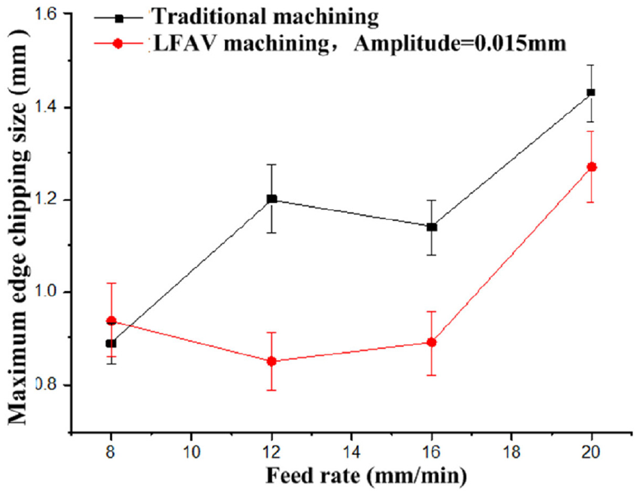
Influence of feed rate on maximum exit edge chipping (spindle speed = 2700 r/min).
Figure 14 shows the change in maximum chipping size with amplitude. Clearly, with the rise in amplitude, the edge chipping size abruptly declined. As can be known that the edge chipping size decreased with the decrease in axial drilling force. According to the above discussed Figures 7 and 8, the LFAV machining caused the axial drilling force decline significantly in the machining process, and with the rise in amplitude, the axial drilling force became smaller, thus resulting in the decrease in edge chipping size.
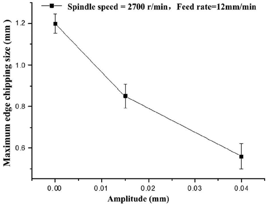
Influence of amplitude on maximum exit edge chipping.
In this test, the workpiece was suspended and clamped on the vice. The instantaneous impact caused by LFAV machining resulted in the unstable exit edge chipping, and so, there would be some fluctuations in the maximum chipping size. However, the overall change trend could be presented above in Figures 13 and 14. When drilling engineering ceramics and other hard and brittle materials, a hard material, such as polytetrafluoroethylene (PTFE), could be padded below the workpiece material to support it and reduce the exit edge chipping.8,9
Conclusion
Combining the specially developed novel thin-wall diamond trepanning bit and the LFAV process, the hole machining process for the constant feed rate of Al2O3 engineering ceramics has been experimentally studied. The influence of the LFAV process on the axial drilling force, hole-wall surface roughness and exit edge chipping size of holes machined has been analyzed intensively. The main conclusions are as follows:
Combining the novel diamond trepanning bit and LFAV process could realize the effective hole machining for a constant feed rate of Al2O3 engineering ceramics. The hole-wall surface roughness parameter, Ra, could reach 0.8–1.6 μm, indicating satisfactory machining quality.
With the increase in feed rate, the axial drilling force increased significantly under both traditional machining and LFAV machining. Compared to traditional machining, LFAV machining could obtain a lower axial drilling force, with a decline extent of 20%–30%. With the rise in amplitude, the axial drilling force declined markedly.
Hole-wall surface roughness increased with the increase in feed rate under both machining methods. The hole-wall surface roughness under LFAV machining was larger than that under traditional machining; with the rise in amplitude, the hole-wall surface roughness increased significantly. However, with the increase in feed rate, the hammering effect of vibration machining weakened and thus the gap in hole-wall surface roughness under the two methods declined.
With the increase in feed rate, the maximum exit edge chipping size of holes produced by the two machining methods both presented a rising trend. Compared to traditional machining, LFAV machining could obtain a smaller edge chipping size. Moreover, with the rise in amplitude, the edge chipping size declined.
Footnotes
Acknowledgements
The authors thank the Jiangsu University Outstanding Innovation Team of China (no. 2017_33) for the experimental conditions support.
Declaration of conflicting interests
The author(s) declared no potential conflicts of interest with respect to the research, authorship, and/or publication of this article.
Funding
The author(s) disclosed receipt of the following financial support for the research, authorship, and/or publication of this article: This work was supported by the National Natural Science Foundation of China (nos 51575470 and 51775260), Jiangsu Provincial Six-big-talent-peak High-Level Personnel Project of China (no. JXQC-029), Qing Lan Project of Jiangsu Higher Education of China (Document 15th of Jiangsu Education Department in 2016) and Postgraduate Research and Practice Innovation Program of Jiangsu Province of China (nos SJCX17-0444 and SJCX17-YG01).