
Abstract
TB6 titanium alloy is extensively applied in lightweight vehicles, biomedicine, and other domains because of its high specific strength, excellent fracture toughness, and excellent corrosion resistance. Electrochemical machining is a non-contact processing technology that has significant advantages in processing materials that are difficult to cut, such as cemented carbide, high-temperature alloys, and titanium alloys. To improve the consistency of deep narrow slots fabricated in TB6 titanium alloy via electrochemical machining, a sheet cathode design and experimental studies were carried out in this work. Based on a unidirectional fluid–structure coupling simulation, the influence of the stiffener arrangement on the cathode rigidity and flow-velocity distribution was studied. Furthermore, by modifying the geometry of the stiffener, the cathode deformation was significantly reduced, and flow-velocity uniformity at the cathode outlet was improved. The influence of a superimposed low-frequency oscillation on the gap distribution and the profile error of a deep narrow slot was investigated experimentally. The results revealed that when an applied voltage of 24 V, an oscillation frequency of 50 Hz, and an amplitude of 0.05 mm were adopted, a highly homogeneous deep narrow slot with an entrance gap of 0.24 mm and a side gap of 0.33 mm was machined into the TB6 titanium alloy.
Keywords
Introduction
Titanium alloys are extensively applied in the military industry, lightweight automobiles, biomedicine, and other domains. 1 Electrochemical machining (ECM) is a technological method that is used for anode removal and is based on the electrochemical anodic dissolution principle. ECM does not involve a mechanical cutting force, is not limited by material mechanical properties, and is very suitable for processing titanium alloy materials.2,3 Titanium alloy deep narrow slots are typically used to reduce the weight of structures, and the current processing methods for titanium alloy deep narrow slots mainly utilize mechanical cutting 4 and electrical discharge machining (EDM). 5 However, with these methods, the tool wear is severe, and the processing cost is remarkably high. Efficient processing of titanium alloy deep narrow slots can be achieved by using ECM, and the tool wear is expected to be significantly reduced. However, the sheet cathode is prone to deformations because of the impact of the high-speed flowing electrolyte in the small gap, which significantly worsens the gap uniformity. Another drawback is that the fluid-frictional drag increases as the tool cathode feed depth increases, and consequently it is difficult to discharge the electrolytic products in a deeper gap in a timely manner. Thus, the homogeneity of the electrolyte conductivity becomes poor, and the enhancement of the processing consistency of deep narrow slots is restricted.
Researchers have proposed some methods to improve the consistency of deep narrow slots produced with ECM, including the optimal design of the tool cathode,6,7 anode shape prediction, 8 a superposition of oscillations in the tool cathode continuous-feed,9–11 high-speed tool cathode rotation,12,13 and the synchronization of the pulse current and oscillation. 14 In addition, there have been many studies on tool cathode design and auxiliary oscillation movement. Jain and Rajurkar 15 attributed the interaction between different parameters as the main cause for the low success of tool cathode design. The authors proposed a finite element formulation and applied the formulation to two-dimensional tool design for electrochemical drilling. McClennan et al. 16 proposed a computational approach for the design of a tool cathode in two-dimensional cases based on solving the electric field equations during the ECM process. Yao et al. 17 designed a hollow thin-walled tool cathode for high-efficiency electrochemical cutting, and the influence of the internal reinforcement structure of the tool cathode on the flow velocity in the frontal gap was analyzed. Moreover, complex structures of different shapes were fabricated with TB6 titanium alloy. Zhao et al. 6 designed a hollow tool cathode to satisfy a rigidity requirement and analyzed the influence of the feeding mode of the tool cathode and the dimension of reinforcement rib inside the tool cathode on the electrolyte flow-velocity distribution. Liu et al. 18 designed a multi-functional tool cathode to restrain the cross-flow in the ECM of parallel grooves and improved the flow-velocity uniformity in each machining gap by utilizing elastic blocks in the non-machining area of the tool cathode. Ghoshal and Bhattacharyya 19 discussed the influence of the tool cathode oscillation, pulsed power supply frequency, and tool tip shape on the ECM of microstructures, and a microgroove with an aspect ratio of 14.33 was fabricated on a stainless steel sheet. Fang et al. 20 facilitated the electrolyte renewal and bubble evacuation in a small gap by superimposing a large-amplitude oscillating movement perpendicular to the tool cathode feed direction, which significantly enhanced the efficiency of wire electrochemical machining (WECM). Qu et al. 21 proposed a WECM method with a slight anode oscillation and improved the narrow slot machining consistency by optimizing the oscillation frequency and amplitude. The abovementioned studies on tool cathode design mainly focused on the influence of the geometric structure on the electrolyte-velocity distribution and rarely investigated the impact action of high-speed flowing electrolyte on the tool cathode. In addition, previous studies mainly concentrated on the influence of an ultrasonic oscillation on the ECM of a narrow slot. As the dimension of the narrow slot extends to the millimeter scale, the improvement of the flow field in the machining gap gradually decreases.
Considering the problem that the sheet cathode in the ECM of deep narrow slots is easily deformed and the processing consistency is low, a unidirectional fluid–structure coupling simulation analysis was employed in this work. The influence of the stiffener setting on the sheet cathode deformation and flow-velocity distribution at the cathode outlet was explored. Based on the optimized sheet cathode structure and a self-developed ECM system, contrast experiments were conducted to explore the influence of a superimposed oscillation movement and the tool cathode feed rate on the machining gap of deep narrow slots fabricated with ECM. Moreover, the profile error of a deep narrow slot was analyzed.
Design of the sheet cathode stiffener
The principle of fabricating a deep narrow slot via ECM is depicted in Figure 1. The workpiece and sheet cathode are fixedly connected to the positive and negative terminals of the power supply, respectively. The high-speed electrolyte continuously flows from the interior of the sheet cathode into the frontal gap. With the continuous feeding of the sheet cathode toward the workpiece, the deep narrow slots are gradually processed. However, the flow velocity at the cathode outlet must be higher to remove the sludges and gaseous products from the frontal gap because of the smaller slot width and higher processing depth. However, the impact of the high-speed flowing electrolyte on the sheet cathode wall is strong, and the rigidity requirement for the sheet cathode is remarkably strict. Therefore, it is of prime importance to explore a design method for the sheet cathode stiffener to achieve processing stability.
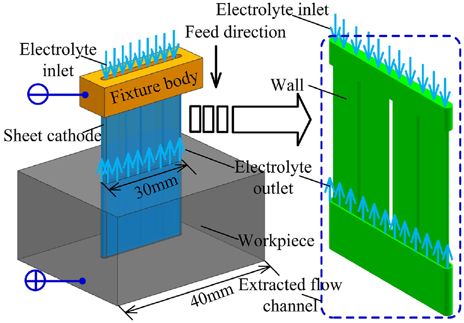
Principle of fabricating a deep narrow slot via ECM.
Figure 2 shows the geometric models of two different sheet cathode structures. To optimize the design of the sheet cathode, the flow fields and static models corresponding to different sheet cathodes were extracted. The effects of the sheet cathode with or without stiffeners, the angle between the stiffener and the cathode wall θ, and the stiffener width b0 on the cathode deformation, and the flow-velocity distribution were analyzed. The frontal gap and the side gap were set to 0.2 mm in the geometric model of the flow field. Figure 3 depicts a section diagram of the sheet cathode outlet. The main geometric parameters of the sheet cathode are as follows: the sheet cathode width is 1.8 mm, the length is 45 mm, the wall thickness is 0.6 mm, and the center distance between the stiffeners is 10 mm.
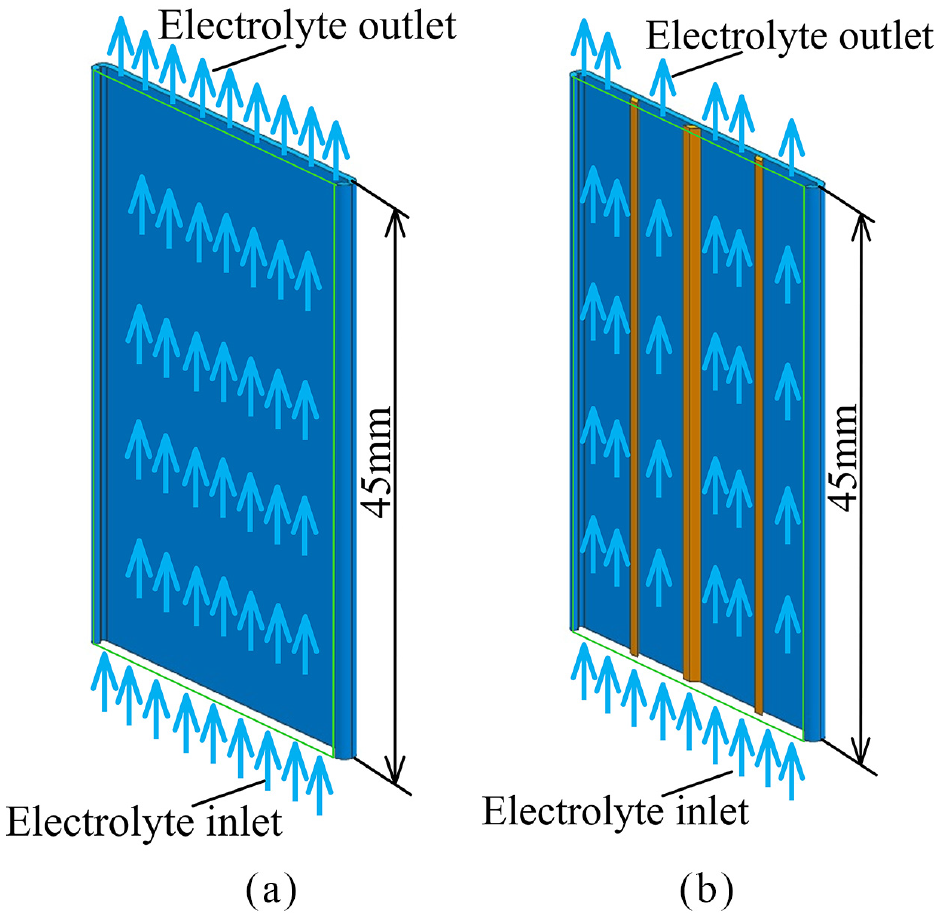
Different sheet cathode models: (a) hollow cathode without a stiffener and (b) stiffener with a height of 45 mm.
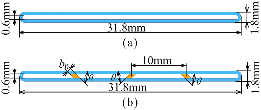
Section diagram of different sheet cathode outlets: (a) hollow cathode without a stiffener and (b) stiffener with a height of 45 mm.
Mathematical model of unidirectional fluid–structure coupling
When using a unidirectional fluid–structure coupling simulation to design the sheet cathode, only the effect of the stiffener distribution on the flow field and rigidity is considered; the influence of the cathode deformation on the flow field distribution is not discussed. Data at the junction of the fluid and cathode are transferred in one direction; only the results of the fluid calculation are transferred to the cathode structure, and the static data are not transferred in the reverse direction.
The mass conservation equation for the electrolyte fluid can be expressed as follows
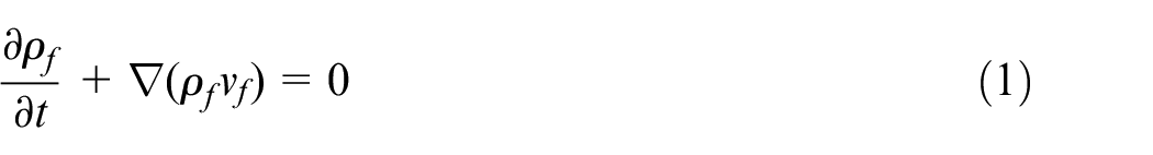
The equation describing momentum conservation is given by
where ff is the fluid volume force vector, ρf is the fluid density, vf is the electrolyte fluid velocity vector, and τf is the fluid shear force tensor.
For the substrate material of the sheet cathode, the conservation equation can be derived by Newton’s second law

where ρs is the density of the cathode substrate material, σs is the Cauchy stress tensor, fs is the volume force vector of the cathode substrate, and
At the fluid–structure coupling interface, the stress τ, displacement d, heat flux q, and temperature T of the electrolyte fluid and the cathode substrate should be equal


where the subscript f denotes the fluid, and the subscript s denotes the cathode substrate.
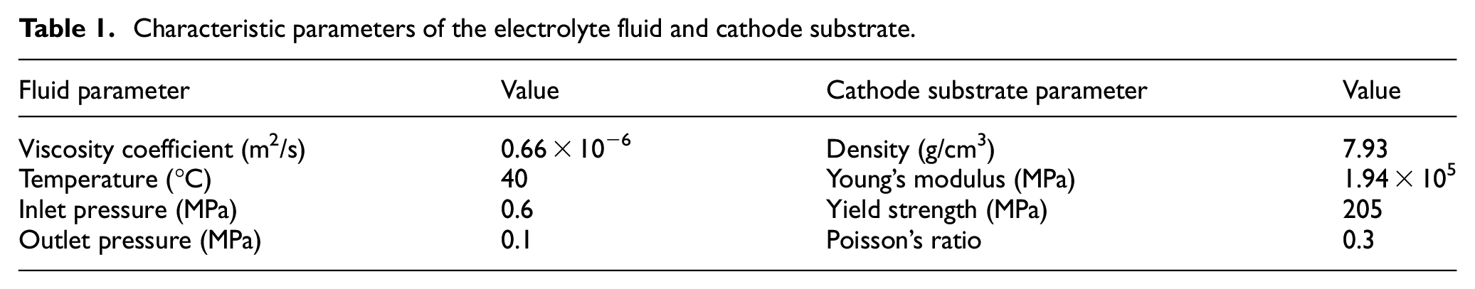
The ANSYS CFX flow-field and static-structural module is employed to simulate the unidirectional fluid–structure interaction, and the standard k–ε model is selected for the electrolyte flow model. The characteristic parameters of the electrolyte fluid and the cathode substrate are shown in Table 1.
Characteristic parameters of the electrolyte fluid and cathode substrate.
Analysis of the calculation results
Effect of the sheet cathode with or without stiffeners on the rigidity
Figure 4 shows the deformation and equivalent stress distribution of the sheet cathode without stiffeners. Figure 5 depicts the cathode deformation and stress distribution when the stiffener height h0 is equal to the sheet cathode height. The angle between the stiffener and the cathode wall θ is 45°, and the stiffener width is 0.6 mm. As shown in Figure 4(a), the sheet cathode deformation is quite small at the sheet cathode inlet near the fixture body due to the tightening effect of the fixture body. At the cathode outlet far away from the fixture body, the sheet cathode deformation is large with the maximum deformation up to 0.258 mm. As depicted in Figure 4(b), the equivalent stress in most areas of the sheet cathode exceeds the yield strength of the substrate material. According to the fourth strength theory, the sheet cathode will exhibit a large plastic deformation under electrolyte pressure. Therefore, it is not feasible to apply the sheet cathode without stiffeners to the ECM of deep narrow slots.
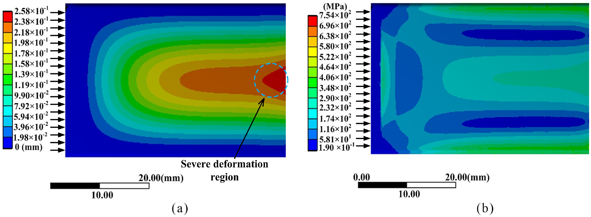
Deformation and stress distribution of the sheet cathode without stiffeners: (a) deformation nephogram of the sheet cathode and (b) equivalent stress nephogram of the sheet cathode.
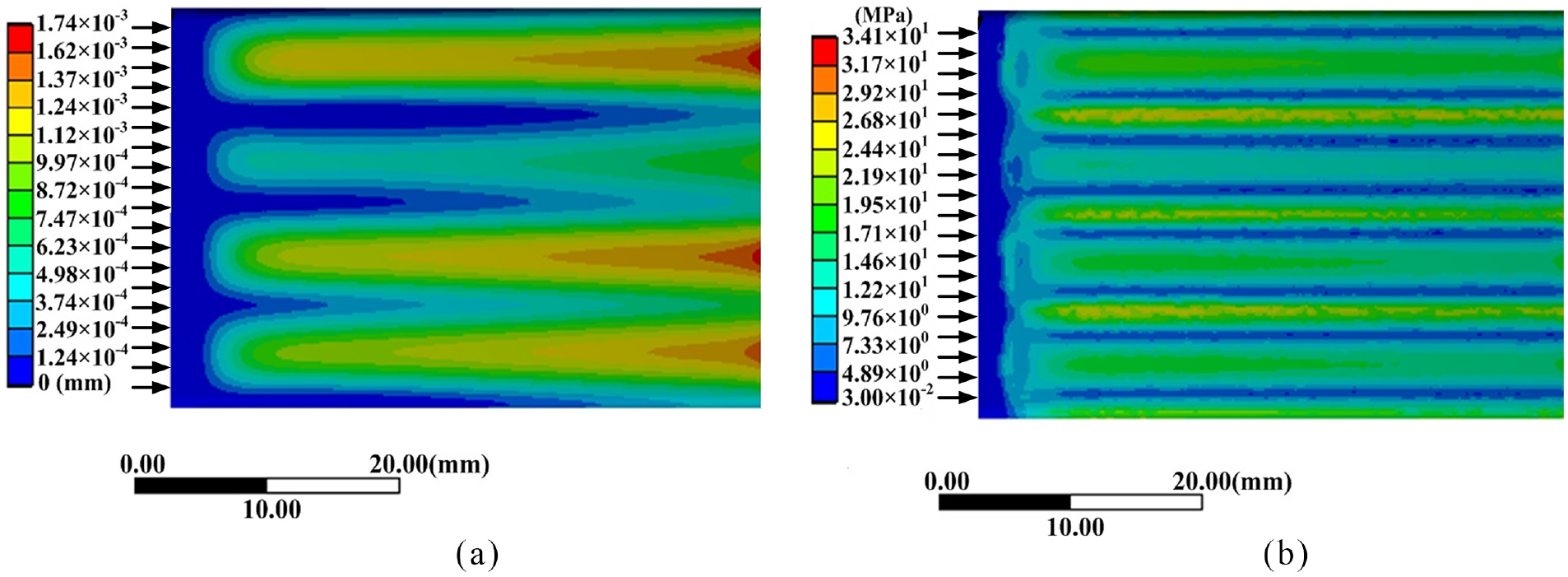
Sheet cathode deformation and equivalent stress distribution (h0 = 45 mm): (a) deformation nephogram of the sheet cathode and (b) equivalent stress nephogram of the sheet cathode.
When the stiffener height h0 is equal to the height of the cathode, it can be seen from Figure 5 that the maximum deformation of the sheet cathode is only 1.74 μm. In addition, the equivalent stress can be limited to 34.1 MPa, which is much lower than the yield strength of the cathode substrate material. Therefore, the influence of the sheet cathode deformation on the ECM process can be neglected.
Effect of the angle between the stiffener and the cathode wall on the rigidity
Figure 6 depicts the distribution of the cathode deformation at different angles (30°, 45°, and 90°). Figure 7 depicts the equivalent stress distribution at different angles. When the angle between the stiffener and the cathode wall is 30°, the maximum deformation of the sheet cathode reaches 1.42 μm and the maximum equivalent stress is as high as 41.4 MPa. When the stiffener is perpendicular to the cathode wall, the deformation at the cathode outlet far away from the fixture body increases significantly, the maximum deformation increases to 3.88 μm, and the maximum equivalent stress reaches 36.3 MPa. As shown in Figures 6(b) and 7(b), the deformation and equivalent stress are relatively small when the angle is 45°. Therefore, the sheet cathode has better rigidity in this case.
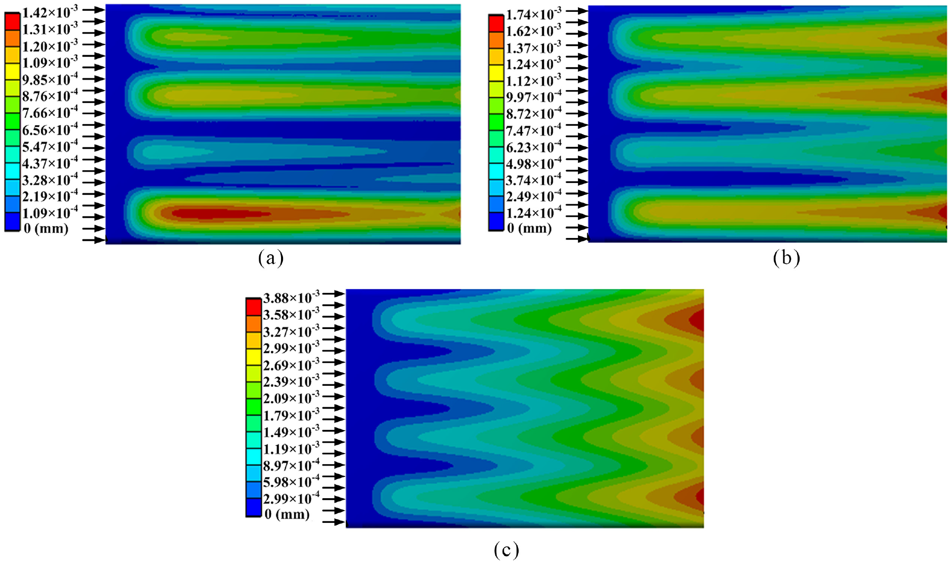
Cathode deformations at different angles: (a) deformation nephogram of the sheet cathode (θ = 30°), (b) deformation nephogram of the sheet cathode (θ = 45°), and (c) deformation nephogram of the sheet cathode (θ = 90°).
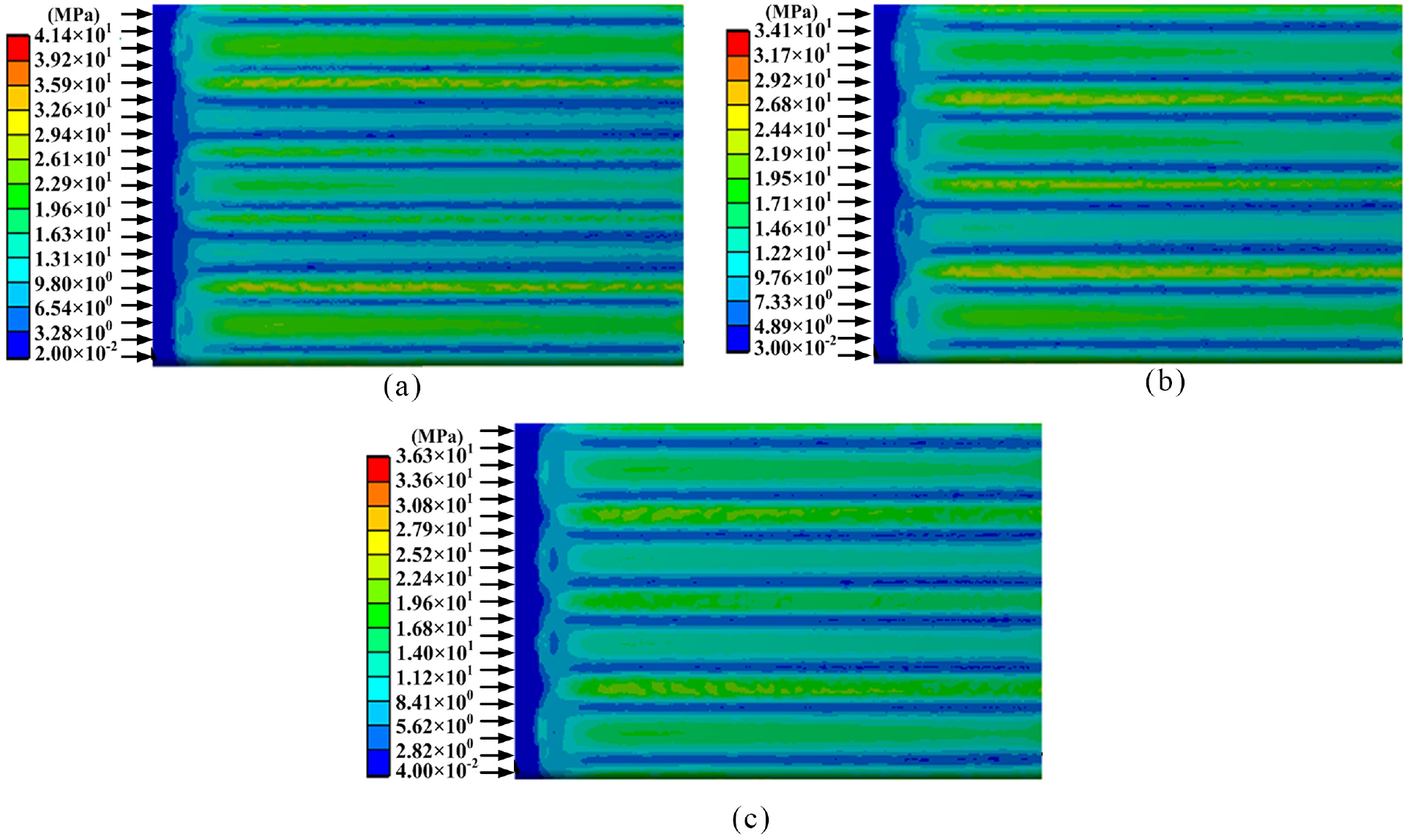
Equivalent stresses at different angles: (a) equivalent stress nephogram of the sheet cathode (θ = 30°°), (b) equivalent stress nephogram of the sheet cathode (θ = 45°), and (c) equivalent stress nephogram of the sheet cathode (θ = 90°).
Effect of the stiffener width on the cathode rigidity and electrolyte flow velocity
During the process of machining deep narrow slots via ECM, the flow field distribution near the cathode outlet will directly affect the diffusion of the electrolytic products and renewal of fresh electrolyte in the machining gap, thus affecting the processing stability. Figure 8 illustrates the sheet cathode deformation with different stiffener widths, and Figure 9 illustrates the flow-velocity distribution at the cathode outlet with different stiffener widths; in both cases, the angle θ is 45°. Considering the deformation nephogram of the sheet cathode, the cathode deformation decreases as the stiffener width increases, but the overall enhancement of the rigidity is limited. However, excessively wide stiffeners will reduce the cross-sectional area of the electrolyte flow and produce an insufficient electrolyte flow rate in the processing area. According to the flow-velocity distributions at the cathode outlet for different stiffener widths, a significant low-velocity region appears at the corresponding position of the stiffener as the stiffener width increases, which will easily lead to the accumulation of insoluble electrolytic products and Joule heating, and then affect the processing stability.
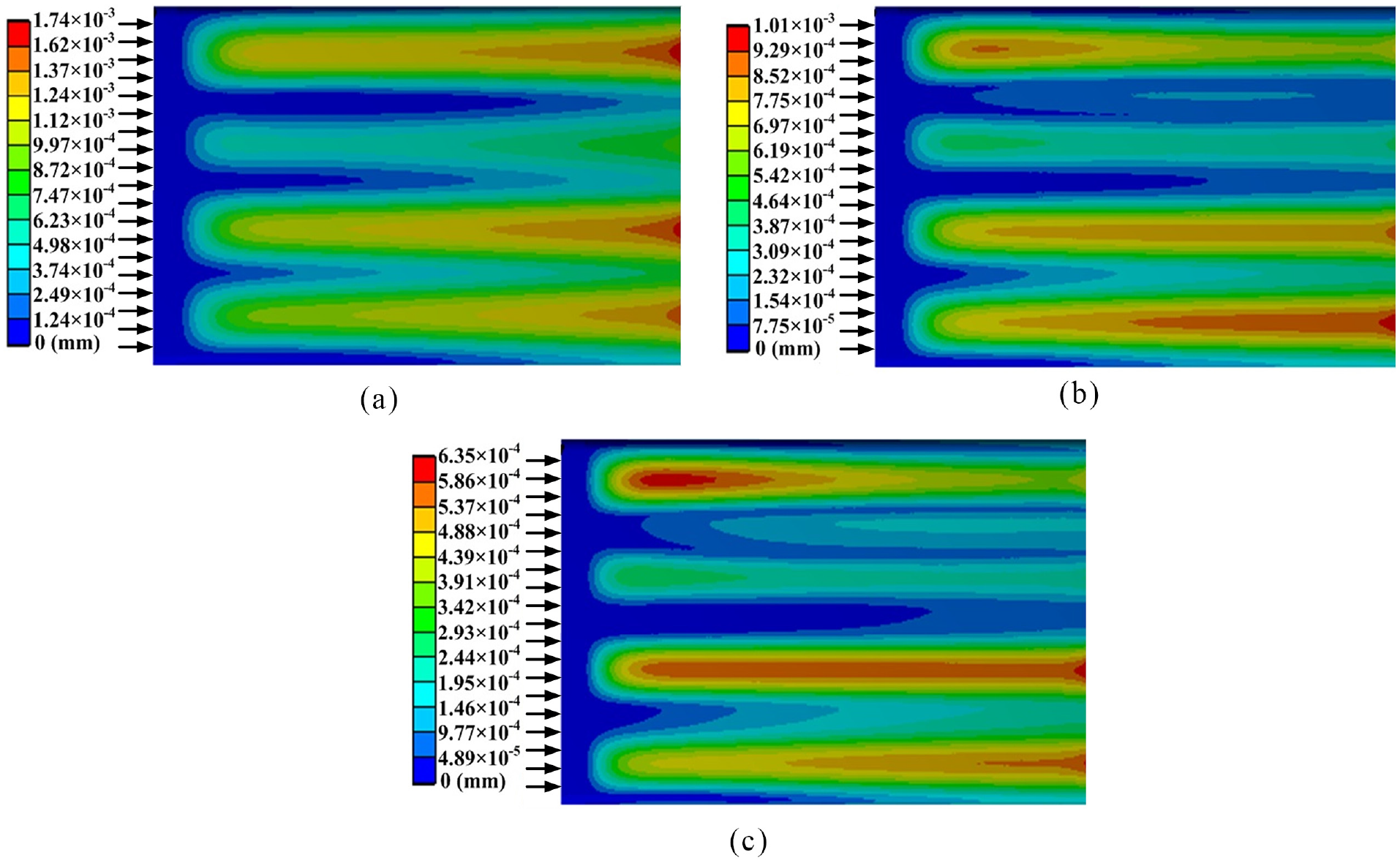
Cathode deformations for different stiffener widths: (a) deformation nephogram of the sheet cathode (b0 = 0.6 mm), (b) deformation nephogram of the sheet cathode (b0 = 1.2 mm), and (c) deformation nephogram of the sheet cathode (b0 = 1.8 mm).
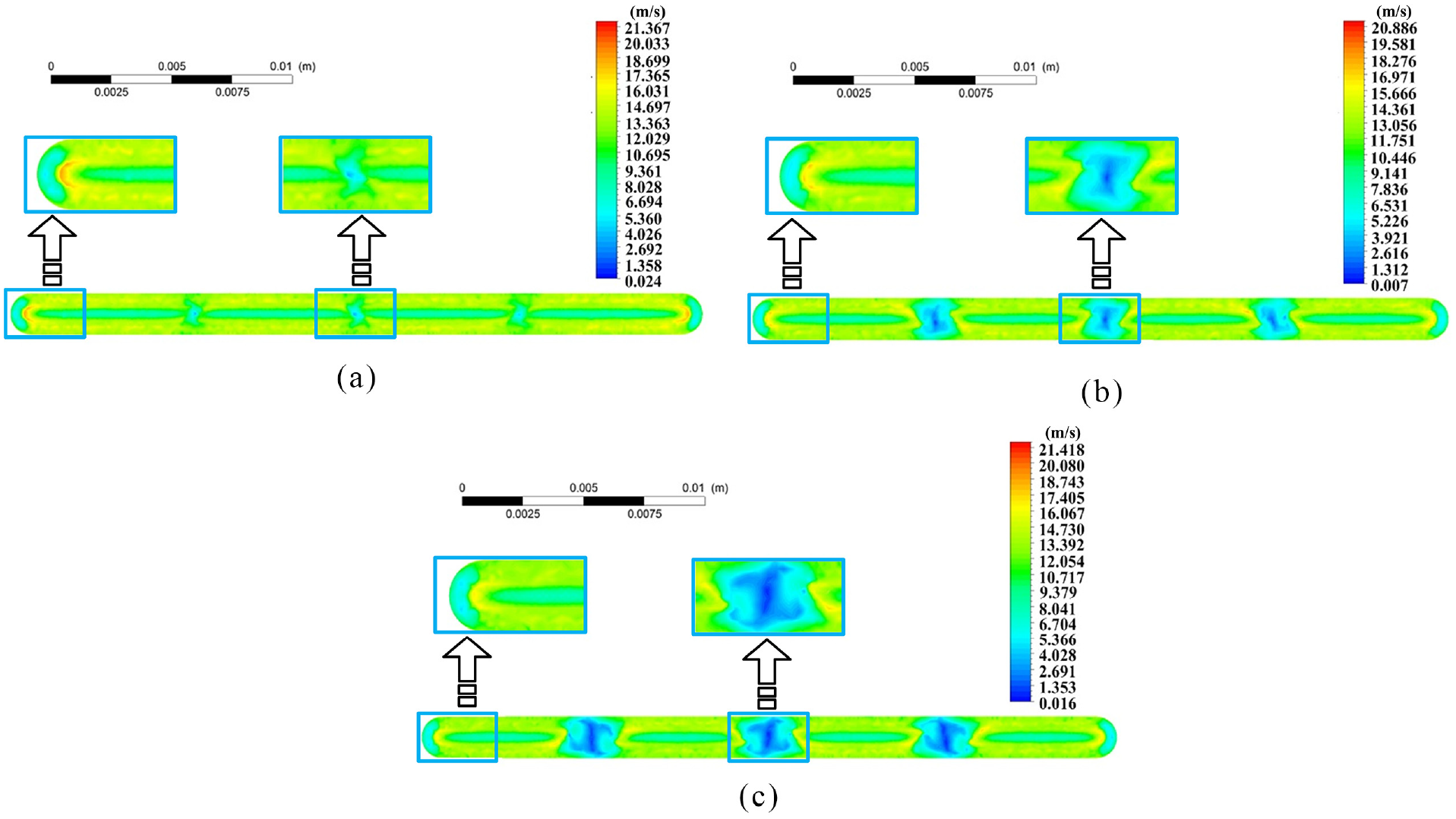
Flow-velocity distributions at the cathode outlet for different stiffener widths: (a) flow-velocity distribution at the cathode outlet (b0 = 0.6 mm), (b) flow-velocity distribution at the cathode outlet (b0 = 1.2 mm), and (c) flow-velocity distribution at the cathode outlet (b0 = 1.8 mm).
It can be concluded from the abovementioned calculation results that the deformation of the sheet cathode without stiffeners is larger, and the equivalent stress exceeds the yield strength of the cathode substrate material. With an increase in the stiffener width, the enhancement of the cathode rigidity is limited, and the low flow-velocity area at the cathode outlet is significantly enlarged. When the stiffener width is 0.6 mm and the angle θ is 45°, the sheet cathode deformation is smaller, and the low flow-velocity area at the cathode outlet is also smaller. Thus, it is feasible to apply a sheet cathode with stiffeners of an appropriate width and angle to the ECM of titanium alloy deep narrow slots.
Effect of the superposition oscillation on the ECM of deep narrow slots
In the ECM of deep narrow slots, a smaller machining gap enables a more uniform dissolution of the anode materials, but the electrolyte mass-transfer process in the small gap is inhibited; thus, a small gap is not conducive to an enhancement of the processing stability. The frontal gap will change periodically when an oscillating movement is superimposed on the tool cathode feed direction. Furthermore, the oscillation has an important impact on the side gap distribution and the machining process, which is expected to improve the processing stability and consistency.
Effect on the machining gap distribution
In continuous-feed ECM of deep narrow slots, when the tool cathode feeding time is long enough and the dissolution rate of the workpiece material reaches a steady state, the frontal gap Δ b can be expressed as
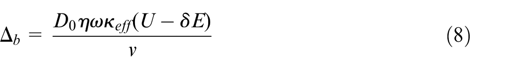
where η is the current efficiency, ω is the volume electrochemical equivalent of the workpiece, U is the voltage applied between the workpiece and the cathode, D0 is the duty cycle of the pulsed power supply, δE is the total electrode potential, and κeff is the effective electrical conductivity.
The effective electrical conductivity satisfies 22
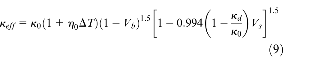
where κ0 is the conductivity of the pure electrolyte, η0 is the temperature coefficient of the specific conductance, ΔT is the temperature increase, Vb is the bubble void fraction, κd is the conductivity of the dispersed medium, and Vs is the sludge void fraction.
The motions and synthesis of the tool cathode continuous feed and oscillating movement are shown in Figure 10. The variation in the displacement S with time t is given by

where v is the tool cathode feed rate, Oa is the amplitude, w is the angular frequency of the oscillation (w = 2πOf, Of denotes the oscillation frequency), and Δ0 is the initial gap.
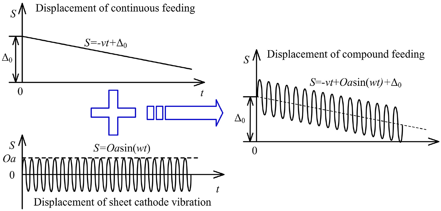
Movement and synthesis of the oscillation and continuous feeding.
When the tool cathode continuously feeds and superimposes an oscillation, the material dissolution rate of the workpiece va is always in a fluctuating state, and the frontal gap Δ Z satisfies

The material dissolution rate va is given by
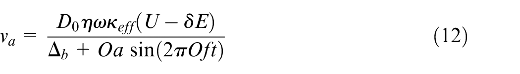
The frontal gap Δ Z tends to Δ b + Oa when the tool cathode retreats, and a large frontal gap is beneficial to the transport of Joule heating and electrolytic products from the processing area. Thus, the processing stability is obviously improved. The frontal gap Δ Z tends to Δ b – Oa when the tool cathode moves to the bottom of the workpiece, and a smaller gap is beneficial to increase the current density in the processing area and improve the local solubility of the workpiece material. However, the oscillation amplitude should be less than the frontal gap, and the bottom of the tool cathode will collide with the bottom of the workpiece when Oa > Δ b , resulting in a serious short circuit. In addition, when the amplitude is too high, serious secondary corrosion occurs in the workpiece sidewall as the tool cathode returns, which is not conducive to enhancing the machining localization.
Effect on the machining process
As shown in Figure 11, the ECM process of a deep narrow slot with a superimposed oscillation can be divided into three stages: the initial stage, tool cathode entry stage, and stable stage. In the initial stage, there is an initial gap Δ0 between the bottom of the tool cathode and the workpiece, the workpiece material dissolution rate is low, and the machining depth h tends to be zero. As shown in Figure 11(b), electrochemical reactions occur at the bottom of the workpiece, and a large number of gaseous products and sludges are generated when the tool cathode feeds rapidly. When the tool cathode returns to the outside of the workpiece, the gaseous products and sludges are discharged rapidly with a sharp increase in the machining gap. In the stable processing stage (h ≫ Oa), because the machining depth of the deep narrow slot is much larger than the oscillation amplitude, the electrolyte renewal in the deeper machining gap is significantly reduced. Thus, sludges and gaseous products accumulate along the flow path and gradually form a stable distribution.
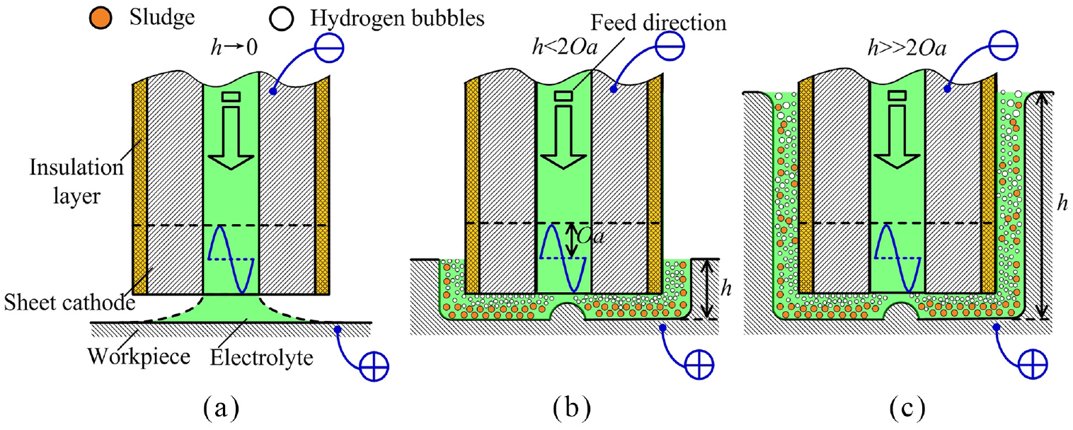
ECM process of a deep narrow slot with a superimposed oscillation: (a) initial stage, (b) tool cathode entry stage, and (c) stable stage.
In the initial stage, because the electrolyte flows out directly from the workpiece surface, the flow field stability is poor, and the workpiece material dissolution rate is low. Thus, a high-amplitude oscillation will lead to a machining gap between the cathode and workpiece that is too small, which will easily lead to short circuits. In the stable processing stage, a higher frequency oscillation is beneficial to enable the discontinuous dissolution effect of the deep narrow slot sidewalls in the light of equation (12) and reduce the spalling of workpiece materials into blocks, thus improving the processing consistency.
ECM system and experimental procedure
Based on the optimal design of the sheet cathode stiffener and theoretical analysis of the influence of a superimposed oscillation on the ECM of deep narrow slots, experiments were carried out on the ECM of TB6 titanium alloy deep narrow slots. To reduce the stray corrosion on the deep narrow slot sidewalls, the insulation coating of the sheet cathode was prepared by electrostatically spraying of enamel powder, and the coating thickness was only 0.1 mm. The electrolyte was a mixture of sodium chloride and sodium nitrate with a mass ratio of 1:1. The mass fraction of the sodium chloride was 20%, the mass fraction of the sodium nitrate was 10%, and the temperature of the mixed electrolyte was maintained at 40°C. To explore the influence of a superimposed low-frequency oscillation on the machining gap and the profile error, an oscillation apparatus driven by a linear voice coil motor was employed to generate the oscillation movement as shown in Figure 12. The key parameters of the oscillation apparatus are as follows: the maximum load weight is 88.2 N, the sustained thrust is 1111.4 N, the range of the oscillation frequency is 0–50 Hz, and the range of the amplitude is 0–1 mm. Moreover, the oscillation displacement error can be limited to 0.01 mm.
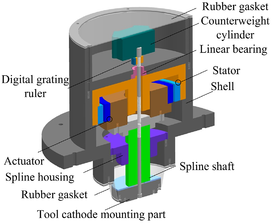
Three-dimensional structure of the oscillation apparatus.
To improve the processing consistency of the ECM of deep narrow slots, the effects of the amplitude, oscillation frequency, and feed rate on the entrance and side gap were studied by means of a single-factor analysis method. Moreover, the profile error of the deep narrow slot was analyzed. The dimensional measurement of the deep narrow slot entrance and side wall is depicted in Figure 13. Five detection positions were selected evenly along the length and depth directions, and the slot width of each detection position was measured by a digital microscope. The entrance gap Δs1 and the side gap Δs2 can be expressed as
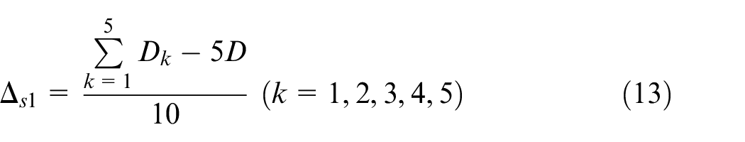
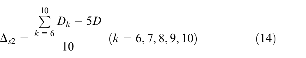
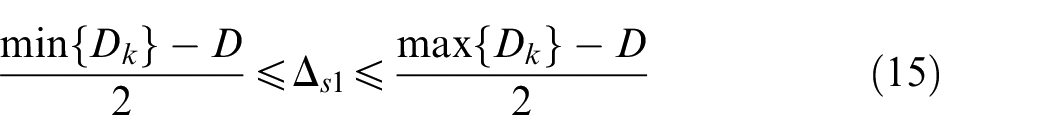
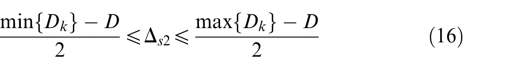
where D is the width of the sheet cathode, Dk (k = 1,2,3,4,5) is the slot entrance width at the five positions, Dk (k = 6,7,8,9,10) is the slot sidewall width at the five positions, max{Dk} is the maximum slot width, and min{Dk} is the minimum slot width.
Dimensional measurement of the deep narrow slot entrance and sidewall.
Results and discussion
Effect of a superimposed oscillation on the gap distribution
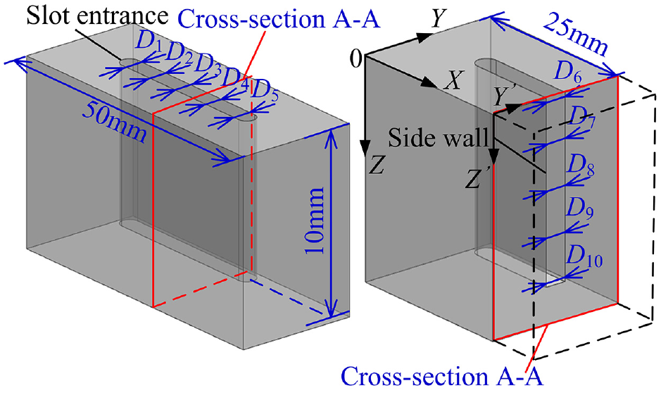
To investigate the effect of a superimposed low-frequency oscillation on the gap distribution in the ECM of deep narrow slots, experiments were conducted with different oscillation parameters. In one case, the oscillation has amplitudes of 0.05, 0.15, 0.25, 0.35, and 0.45 mm and a frequency of 10 Hz. In another case, the oscillation frequency is 10, 20, 30, 40, and 50 Hz, and the amplitude is 0.25 mm. Figure 14 depicts the entrance and side gap for the different oscillating movements. The applied voltage is 24 V, and the tool cathode feed rate is 1 mm/min. Figure 15 shows the titanium alloy deep narrow slots processed with different oscillating movements.
Entrance and side gap with a superimposed oscillation: (a) entrance and side gap for different amplitudes and (b) entrance and side gap for different oscillation frequencies.
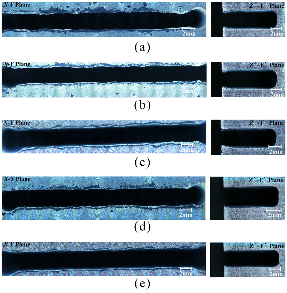
Deep narrow slots processed with different oscillating movements: (a) Oa = 0.05 mm, Of = 10 Hz; (b) Oa = 0.25 mm, Of = 10 Hz; (c) Oa = 0.45 mm, Of = 10 Hz; (d) Oa = 0.25 mm, Of = 20 Hz; and (e) Oa = 0.25 mm, Of = 40 Hz.
As depicted in Figure 14, the entrance and side gap change slightly with increasing amplitude and oscillation frequency when the applied voltage and tool cathode feed rate are fixed, but the gap error decreases significantly. In addition, the entrance gap is significantly smaller than the side gap, but the side gap error is smaller.
Increasing the amplitude and oscillation frequency is beneficial for the discontinuous dissolution of the workpiece sidewalls and the evacuation of reaction products in the gap, thus improving the uniformity of the effective electrical conductivity distribution along the flow path and reducing the gap error. However, the secondary corrosion area of the deep narrow slot side wall continues to expand as the amplitude increases, which restricts the reduction in the side gap. In addition, the flow field fluctuates violently, and the flow velocity is low in the initial stage of the ECM of deep narrow slots. Then, the workpiece material exhibits a remarkable inhomogeneous dissolution, the entrance gap is small, but the gap error is large.
Effect of the feed rate on the gap distribution
Figure 16 depicts the variation in the entrance and side gaps for different tool cathode feed rates. The applied voltage is 24 V, the amplitude is 0.05 mm, and the oscillation frequency is 50 Hz. Figure 17 shows the titanium alloy deep narrow slots processed with different cathode feed rates. As the feed rate increases, the entrance gap, the side gap, and the gap error all exhibit a significant downward trend, and the side gap gradually becomes close to the entrance gap. When the feed rate is 2.2 mm/min, the entrance gap is 0.24 mm, and the side gap is 0.33 mm.
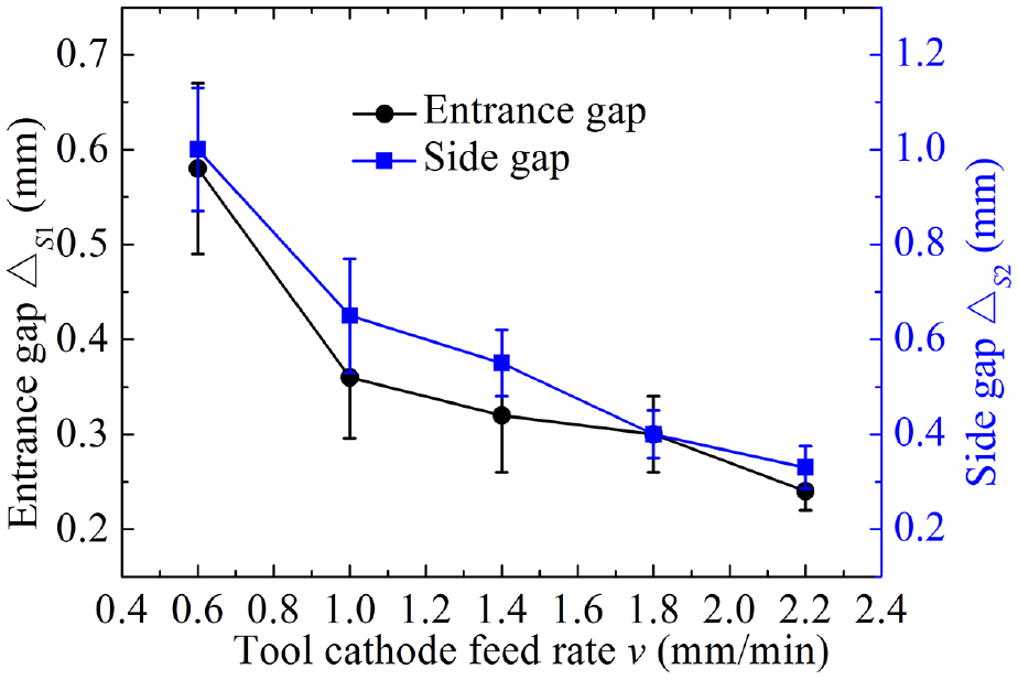
Entrance and side gap for different feed rates.
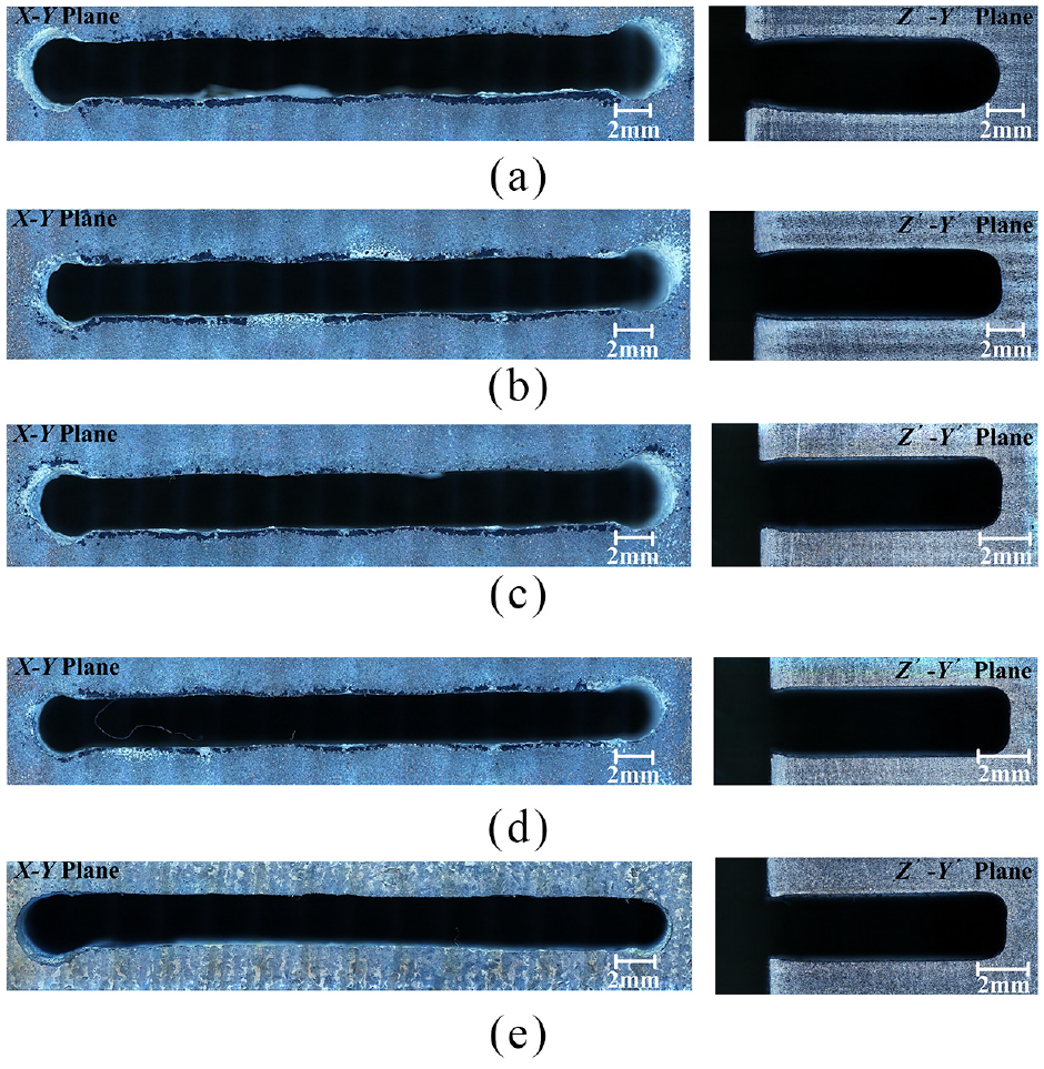
Deep narrow slots processed with different tool cathode feed rates: (a) v =0.6 mm/min, (b) v =1.0 mm/min, (c) v =1.4 mm/min, (d) v =1.8 mm/min, and (e) v =2.2 mm/min.
When the machining depth of the deep narrow slot is fixed, the processing time at the entrance and sidewall decreases significantly as the tool cathode feed rate increases, and then the stray corrosion decreases significantly. Therefore, the gap error decreases, and the processing consistency of the deep narrow slot increases remarkably. In light of Faraday’s law, the volumes of the removed material at the entrance and side wall decrease significantly as the tool cathode feed rate increases, and then the machining gap decreases gradually.
Profile error analysis of the deep narrow slot
Figure 18(a) shows the error between the processed profile and the theoretical profile at the deep narrow slot entrance. The theoretical profile is plotted according to the design and processing requirements of the deep narrow slot. Figure 18(b) depicts the profile error at the deep narrow slot sidewall. The oscillation frequency is 50 Hz, the amplitude is 0.05 mm, the tool cathode feed rate is 2.2 mm/min, and the applied voltage is 24 V. According to the profile error distribution at the deep narrow slot entrance, the profile error in the middle position is relatively small, the maximum profile error can be limited to 0.04 mm, and the profile error on both sides of the deep narrow slot increases significantly. The processed profile of the deep narrow slot side wall is significantly larger than the theoretical profile. The profile error in the middle of the side wall is larger, but the error distribution is more uniform; the profile error near the deep narrow slot entrance is smaller, but the error fluctuation is larger.
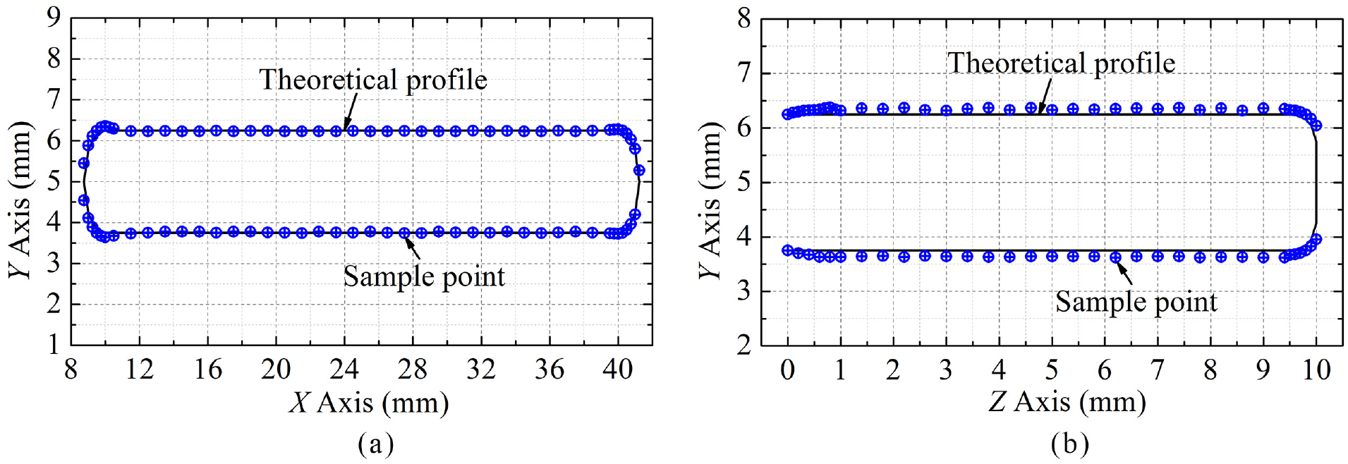
Profile errors at the deep narrow slot entrance and sidewall: (a) profile error at the entrance and (b) profile error at the side wall.
Titanium alloy materials are very sensitive to flow field fluctuations. In the initial stage of the ECM of the deep narrow slot, the volumes of the removed material near the slot entrance are low, and the dissolution uniformity is poor owing to the low flow velocity and violent fluctuation of the electrolyte flow field. Therefore, the profile error fluctuation is larger. In the stable stage, the electrolyte flow resistance in the side gap increases gradually as the machining depth increases, and the flow-velocity distribution tends to be stable. Thus, the titanium alloy material achieves a stable dissolution state, and the profile error distribution is more uniform. According to results of the unidirectional fluid–structure coupling simulation, the electrolyte flow velocity on both sides of the cathode outlet changes sharply, and the dissolution uniformity of the titanium alloy material is poor. Consequently, the profile error is also large.
Conclusion
Based on a unidirectional fluid–structure coupling simulation analysis, a sheet cathode structure with good rigidity was obtained. The center distance between the stiffeners inside the cathode was 10 mm and the stiffener height was 45 mm. When the stiffener width was 0.6 mm and the angle between the stiffener and the cathode wall was 45°, the sheet cathode deformation was small and the low-velocity area at the cathode outlet was also small.
When the applied voltage and the feed rate were fixed, the machining gap changed slightly with an increase in the amplitude and oscillation frequency, but the gap error decreased significantly. The machining gap and gap errors were significantly reduced by increasing the feed rate, and the processing consistency of the deep narrow slot was significantly improved.
The results of the profile error distribution demonstrated that the profile error in the middle of the slot entrance was small and could be limited to 0.04 mm. The processed profile of the deep narrow slot side wall was significantly larger than that of the theoretical profile. The profile error in the middle of the side wall was larger, but the fluctuation was small.
Footnotes
Appendix 1
Declaration of conflicting interests
The author(s) declared no potential conflicts of interest with respect to the research, authorship, and/or publication of this article.
Funding
The author(s) disclosed receipt of the following financial support for the research, authorship, and/or publication of this article: This research was sponsored by the National Natural Science Foundation of China (Grant No. 51475235), Funding for Outstanding Doctoral Dissertation in NUAA (Grant No. BCXJ16-05), and Fundamental Research Funds for Central Universities (Grant No. 3082018NF2018006).