
Abstract
A non-axisymmetric cylinder with an oblique flange has broad application prospects. Spinning is the main production process for this kind of workpiece. Finite element modeling is a necessary method to study some key problems that are difficult to be solved merely through experiments, such as the strain and stress fields in the development of this spinning technology. In this study, the spinning process of a non-axisymmetric oblique flange cylindrical part was established and simulated using ABAQUS/explicit software. The credibility of the simulation result was validated through an experiment. The influence of the axial roller feed along the cylinder wall on the distribution of wall thickness and stress and strain during the forming process was analyzed. The change in stress field and strain field with time was analyzed, and the quantitative relationship between forming conditions and forming results was described. Furthermore, the forming principle of the flange was analyzed. It would be beneficial for flange forming to reduce the increasing distance of the cylinder wall in the 180° direction (parameter c) and the vertical distance from the closest point to the spindle as the roller returns back in the 180° direction (parameter d), to a certain extent. Hence, a workpiece with an ideal appearance was obtained. By comparing the wall thickness distribution, the design and optimization of the roller path were once again verified to be reasonable.
Keywords
Introduction
In the fields of aviation, agricultural machinery, and automobile, non-axisymmetric parts are widely used. However, the manufacturing process of non-axisymmetric parts is usually difficult to achieve. Based on the research on various metal forming theories and technologies,1,2 traditional spinning was found to be mainly used when producing axisymmetric hollow parts. Due to the wide application of finite element simulation in the spinning process, Bai et al. 3 have established a three-dimensional elastic-plastic finite element model of a thin-walled aluminum alloy shell with ring internal ribs in the ABAQUS software. Hua et al. 4 established a three-dimensional elastic-plastic finite element model of a barrel spinning with three rolls. The model was used to simulate and analyze the phenomena of bell mouth, stacking, bulging before and between rolls, and diameter r during barrel spinning. Ma et al. 5 adopted the method of combining the finite element method (FEM) with experiments to investigate the forming process of conical parts with transverse inner ribs under different process parameters.
In recent years, the metal spinning process has been effective in forming non-axisymmetric parts. 6 Arai 7 used a hybrid force/position control system that allows the rollers to follow the non-axisymmetric path, and a non-axisymmetric shape was successfully formed using this shear spinning method. Xia et al.8,9 conducted the numerical simulation of the single-pass and multi-pass spinning process of an inclined pipe fitting. It was considered that the shape makes the deformation, stress–strain field, and wall thickness distribution of the spun part appear with a non-axisymmetric property. Since then, Akio and Hirohiko 10 attempted to control the distribution of wall thickness and claimed that the synchronous model-free rotation method is suitable for controlling wall thickness. Wang and Long11,12 investigated the multi-pass conventional spinning process and revealed that wall thickness gradually decreases after each pass of the roller path. Jia et al. 13 established the finite element model of the non-axisymmetric tapered die-less spinning process and simulated the spinning process using the main boundary condition of the rolling path equation. Han et al. 14 concluded that in axisymmetric shear spinning, the thickness change of the oblique cone in different directions is consistent with the sine law. The above researches show that hollow spinning is flexible for many products and that the distribution of wall thickness is affected by the roller path.
An increasing number of scholars have used the computer numerical control spinning lathe to realize the non-axisymmetric shape by changing the roller path. For example, Pan et al. 15 sorted the existing main research achievements in the conventional spinning process and roller path. Huang et al. 16 provided a new idea of parametric design for the non-axisymmetric roller path. It can be observed that the design of the roller path plays a decisive role for parts with complex geometric features. A novel flanging process on a cylinder with a large diameter–thickness ratio was simulated by Fan et al. 17 through FEM. Xiao et al. 18 studied the non-axisymmetric multi-pass rotation characteristics of the oblique flange cylinder. A set of roller passes was designed to achieve the oblique cylindrical shape with a planar flange. The working principle of synchronous multi-pass spinning adopted by that study focused on the fact that the radial and axial positions of the roller are synchronized with the spindle rotation in every pass set, and this usually presents a pair of curves arranged on the symmetrical plane of the spinning system. The whole multi-pass roller path is integrated from all the pass sets. Spinning parts with a good shape were obtained, as shown in Figure 1. The inclined flange cylinder has a wide range of applications, such as aircraft dashboards, lampshades, agricultural machinery, and other aspects. The metal flow and stress state analysis in the complex spinning process is difficult to achieve through existing physical experiments. However, the FEM can solve this problem.
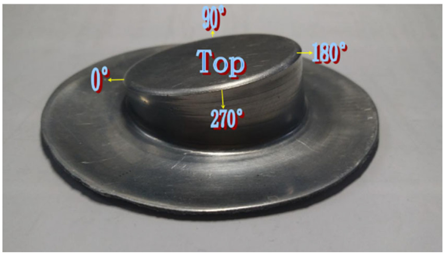
The product of the non-axisymmetric cylinder with an oblique flange.
In this study, the important boundary of the condition corresponding to the non-axisymmetric tube spinning path was developed. Based on that, the three-dimensional finite element model of the non-symmetric oblique flange cylinder was established. This molding process was investigated using the finite element simulation method, providing a theoretical basis for subsequent experiments and production. Furthermore, this would improve the manufacturing of non-axisymmetric cylindrical parts with an oblique flange.
Establishment of the finite element model
The spinning process of the non-axisymmetric oblique flange cylindrical part was established and simulated using the ABAQUS/explicit software, according to the actual situation of the spinning experiment, which was performed in advance. 18 The roller, spindle, and tail cap were set as rigid bodies. Each rigid body was assigned with a reference point (RP) to represent its rigid motion in all degrees of freedom. The assembly diagram of the spinning system is shown in Figure 2. The metal flow on the top of the workpiece is small, and the thickness is uniform during the spinning process. The difficulty of workpiece forming mainly lies in the adhesion of the cylinder wall, the fracture of the connection between the cylinder wall and flange, and the wrinkling of the flange. In summary, a billet with a diameter of 100 mm is defined as a three-dimensional deformable entity, and a two-layer grid would be assigned to the billet in the height direction. The grid was divided into 24,370 units, and the shape was set to C3D8R, which means, “8-node linear brick, reducing integral and hourglass control.” The central circle is restrained by the spindle and tail cap. The rotation speed of the spindle, tail cap, and billet was the same and was set at 12 r/min. The roller could move along the radial and axial direction (Figure 2) and rotate around its central axis freely with a diameter of 110 mm and a working radius of 2 mm. The feed speed of the roller was 1 mm/r. The working angle between axes of the roller and spindle was 45°. There was no lubrication between the tail cap, billet, and spindle, and the friction coefficient was set to 0.4, according to production experience. The friction coefficient between the roller and billet was set to 0.15, which was lubricated by oil. The roller was driven to rotate around its central axis through the billet due to the friction. At the same time, the roller moves in the axial and radial direction under the control of the roller path program. The core of the roller path program is the relationship of the axial and radial movements of the roller, which is expressed as the roller path equation. A 6061 aluminum alloy (annealed) was used for the material of the billet, with a diameter and thickness of 100 and 1.2 mm, respectively. The constitutive equation of the 6061 aluminum alloy (annealed) was obtained from Xiao et al. 18 The mathematical expression is

where σ is the true stress and ε is the true strain.
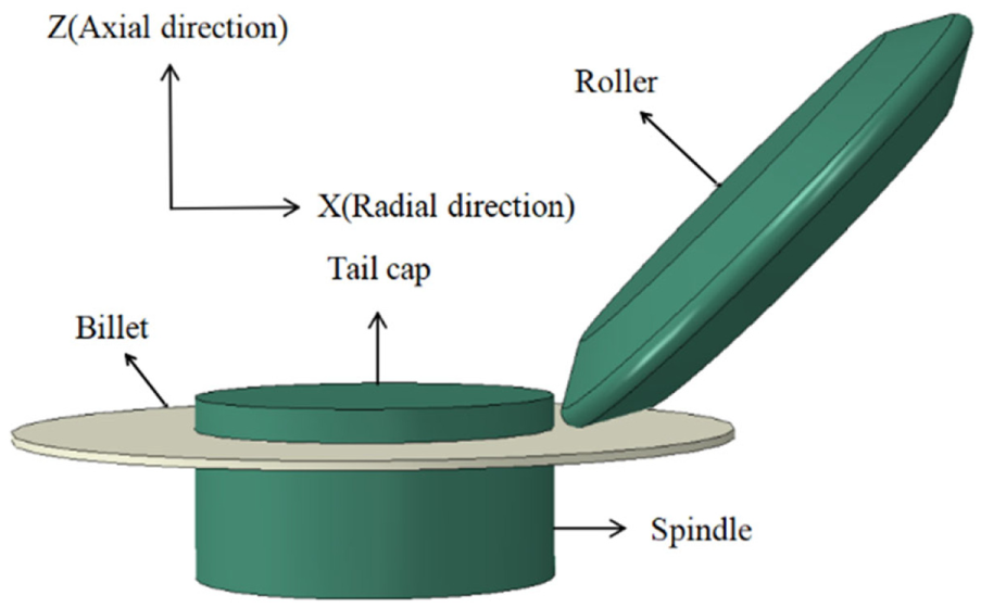
Assembly drawing of the non-symmetric spinning.
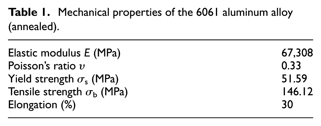
The mechanical properties of the metal are presented in Table 1.
Mechanical properties of the 6061 aluminum alloy (annealed).
Under the boundary condition, the finite element model of the non-axisymmetric cylindrical multi-pass spinning was established using the ABAQUS software.
Roller path on the flange
The roller path would affect the forming angle of the inclined flange and the distribution of wall thickness. The reasonable setting of the roller path is the key to the success of the model. Hence, the solution for the roller path equation is particularly important. Figure 3 shows the axial and radial motion of the roller on the flange. In order to form the non-axisymmetric oblique flange cylinder parts, the position of the shortest wall was delimited as the 0° direction, while the position of the longest wall was delimited as the 180° direction. The starting point of the roller was also arranged in the 0° direction. Since the depth at different angle direction was different, two different axial paths were jointly needed to establish the roller path, which is different from the conventional Archimedes spiral.
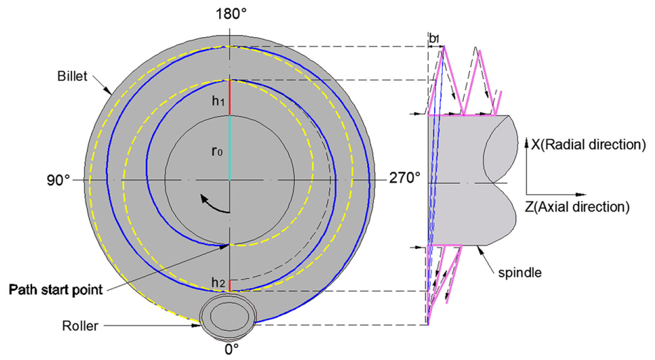
Path of the roller on the flange.
In order to deduce the roller path formula, the circular disk billet was divided into several areas. The billet was divided into four areas in this study (Figure 3): 0°–90°, 90°–180°, 180°–270°, and 270°–360°.
The roller speed in 0°–180° and 180°–360° along the radial direction is inconstant. In order to simplify the derivation of the formula, the first lap of the roller feed was analyzed. The radial motion equation was expressed as follows
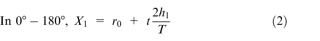
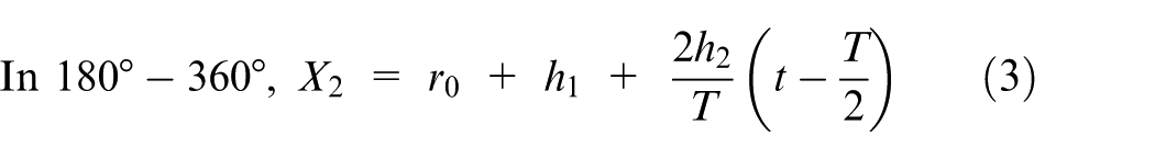
where h1 is the radial movement for the billet rotating from 0° to 180°, h2 is the radial movement with a spinning process of 180°–360°, T is the rotating time of the billet, and r0 is the distance between the initial position of the roller to the rotating center.
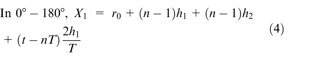
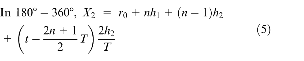
When the spindle drives the billet to rotate for n circles, the radial feed of the roller can be calculated as follows
The axial motion law of the roller can be obtained by the similarity of the triangles. The equation for the first-cycle axial feed of the roller is given as follows

where b1 is the axial feed with the billet rotating from 0° to 180° and b2 is the axial feed with the billet rotating from 180° to 360°.
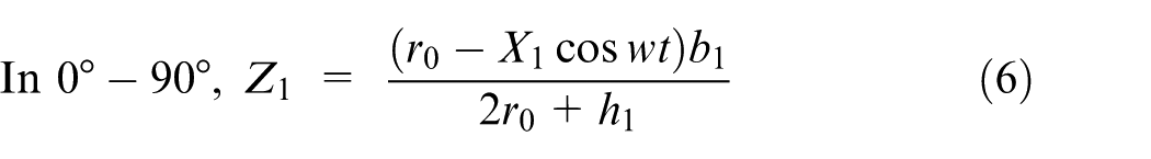
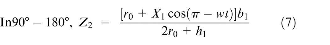
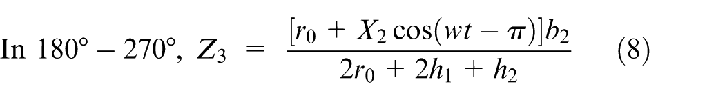
The first sub-axial motion law of the roller is deduced, and the equations are expressed as follows
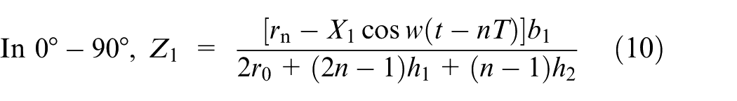

When placing equations (4), (5), and (14) into equations (10)–(13), the following equations can be obtained


Roller path on the cylinder wall
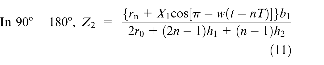
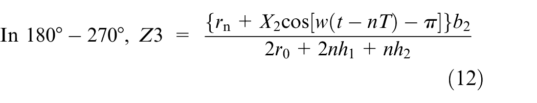
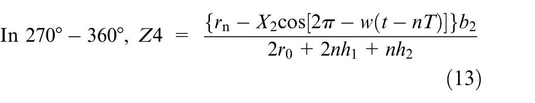
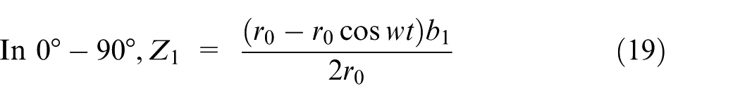
When the roller arrives at the flange edge, the radial movement of the roller would turn back and become a contraction feed. The material is taken to the spindle in this process. After a certain degree of shrinkage on the billet flange, a cylinder wall would be formed to prevent the billet flange from excessive shrinkage, which would cause the cylinder wall to break. A schematic diagram of the roller axial motion on the cylinder wall and its corresponding radial motion is presented in Figure 4. The radial position of the roller is constant and close to the spindle. The movement rule in the axial direction can also be analyzed by dividing the whole path in a 360° direction into equal numbers of segments and connecting the corresponding segmented points. The axial roller path on the cylinder wall is deduced, as presented in equations (19)–(22).The trajectory is as follows
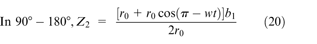
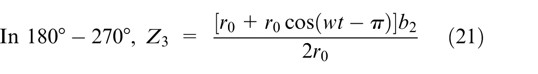
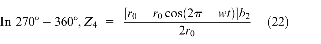
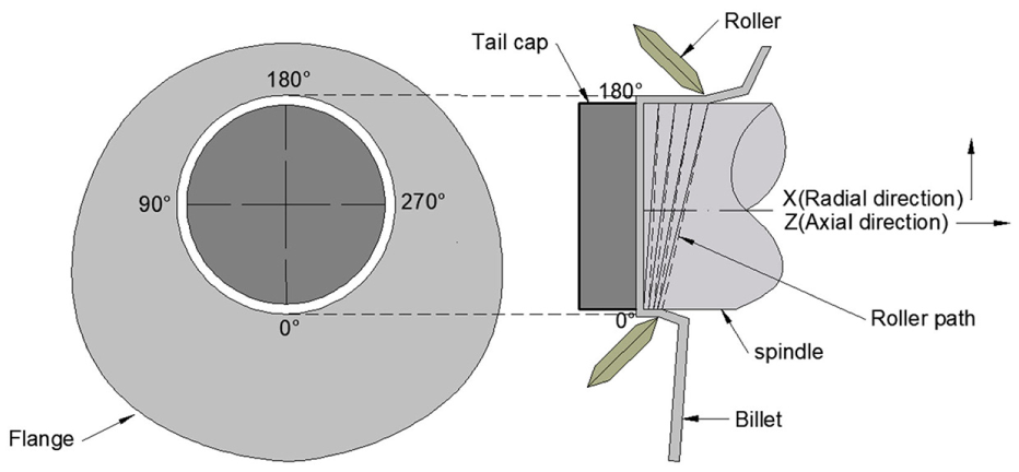
The path of the spinning roller on the drum wall.
Simulation results and discussion
Forming process
Figure 5 shows the deformation process of the non-axisymmetric oblique flange cylinder. It can be observed that as the axial length of the workpiece increases, the non-axisymmetric cylinder wall and oblique flange gradually forms. Therefore, the deformation process shows that the roller path formulas and boundary conditions are theoretically reasonable. The complex spinning process can be achieved through the FEM.
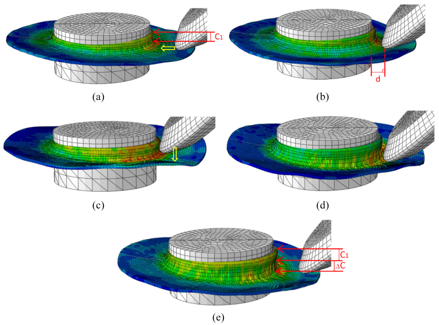
Deformation process of the non-axisymmetric spinning: (a) 70s; (b) 75s; (c) 80s; (d) 85s; (e) 95s.
No obvious springback was found on the asymmetric cylinder wall, as shown in Figure 5. Figure 6 presents the distribution of the flange inclination angle in the four directions. It was found that a slight angular deviation occurred on the flange, and the maximum deviation between the simulation result and theory value was more than 5%.
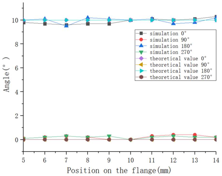
Distribution of the flange inclination angle in the four directions.
Modeling influencing factors and optimization
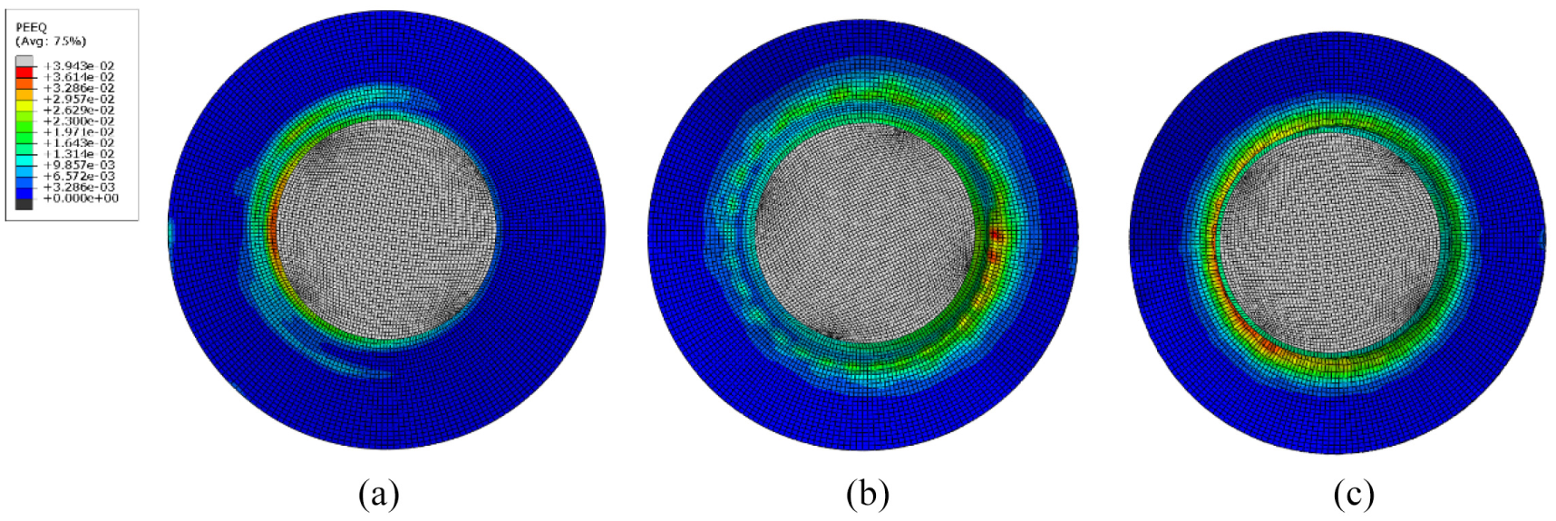
Ge et al. 19 pointed out that reasonable adjustment of key process parameters can improve the forming accuracy of spinning. Figure 5 shows the forming process of the cylinder wall in the 180° direction. Parameter c (Figure 5) represents the distance of the cylinder wall in the 180° direction. Parameter Δc (Figure 5) represents the increasing distance of the cylinder wall in the 180° direction. Parameter d (Figure 5) represents the vertical distance from the closest point to the spindle as the roller returns back in the 180° direction. These two parameters were found to have an influence on forming quality through the numerical simulation. The strain fields under the conditions of d = 3, 2, and 1 mm are shown in Figure 7. When d = 3 mm, the maximum equivalent strain value was 1.959. When d = 2 mm, the maximum equivalent strain value was 1.842. When d = 1 mm, the maximum equivalent strain value was 1.633. This shows that the strain value decreases with the decrease of d. However, serious wrinkling occurs on the three flanges, which cannot be eliminated by reducing the parameter d. When the parameter c is reduced from 3 to 1 mm, a much smoother straight-oblique flange could be obtained by simulation, as shown in Figure 8.
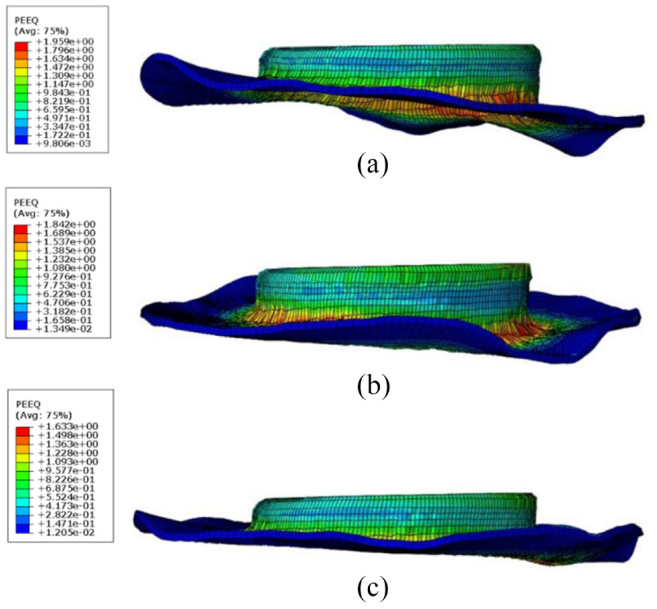
Simulation results under the conditions of (a) d = 3 mm, (b) d = 2 mm, and (c) d = 1 mm.
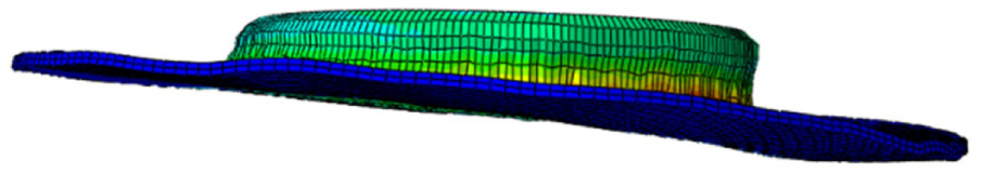
Simulation result with the optimized parameters of d and c.
In order to verify the credibility of the simulation, a spinning experiment using the same process parameters with the optimized model was carried out on the PS-CNCSXY 5 spinning machine. Figure 9 shows the morphology comparison between the experiment and simulation. It could be observed that both morphologies of the spun workpieces present the shape of the non-axisymmetric cylinder with a straight-oblique flange, and the designed roller path and optimized parameters can be used to spin out the shape. After that, the length of the simulated cylinder wall in the 0° direction was measured as 5.7 mm. In the 90° direction, the measurement was 10.2 mm. In the 180° direction, the measurement was 14.7 mm. In the 270° direction, the measurement was 10.1 mm. In the experiment, the corresponding lengths of the cylinder wall were 6, 10.5, 14.8, and 10.4 mm, respectively. The credibility of the simulation was verified by the small differences in morphology and geometric size between the simulated and experimental workpieces.
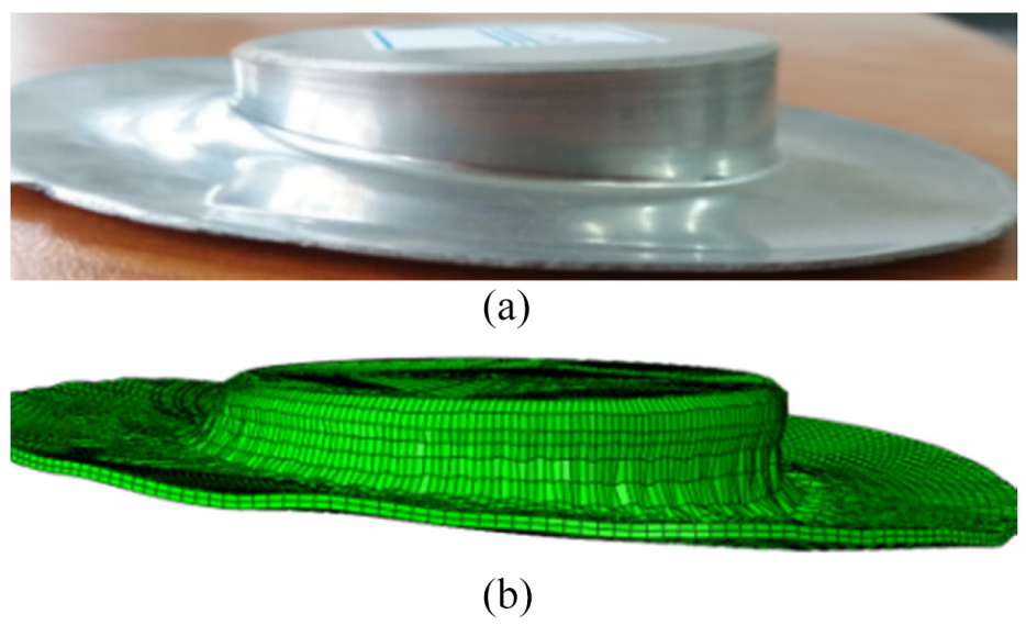
Morphology comparison of the workpiece: (a) experiment and (b) simulation.
Wall thickness distribution
The wall thickness changed constantly during the forming process. Figure 10 shows the thickness distribution of the cylinder wall, which was obtained from the experiment and simulation. In the four angle directions, the maximum wall thickness deviation between the experimental and simulated results was no more than 15% at the corresponding position. Both cylinder thicknesses gradually decreased with the distance far away from the workpiece top (Figure 10). The simulation result coincides with the experimental result, and the credibility of the modeling was proven again. The simulation result revealed that the cylinder wall distribution in the four angles differed. The 180° and 270° direction wall thickness was the largest, while the smallest appeared in the 0° and 90° direction. The distribution pattern of the wall thickness was consistent with that reported in Fan et al. 17 The reason for this phenomenon is that the material thinned and displaced in the direction opposite to the motion of the roller (backward tube spinning), since the rotating was through 180°. Hence, wall thickness was greater in the region from 180° to 270°, when compared to that from 0° to 90°.
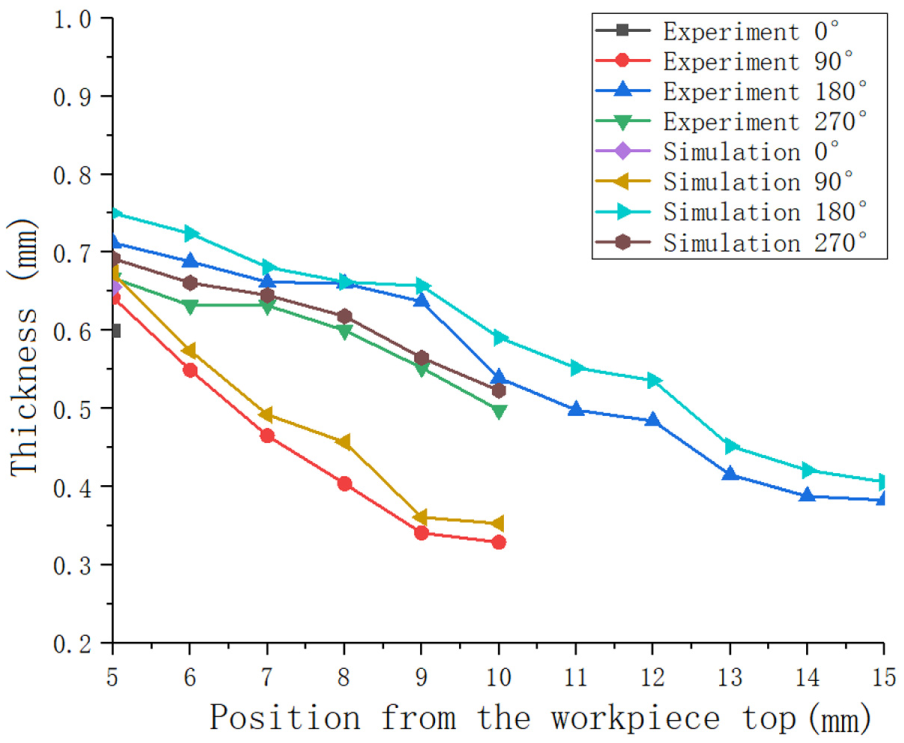
Thickness distribution of the cylinder wall.
Figure 11 shows the wall thickness distribution of the flange. This shows that both flanges formed by modeling and the experiment were thickened from the inside to the outside. The maximum thickness deviation between these two results was not more than 10%. The flange thickness also exhibited an uneven distribution in different angle directions. However, the thickness difference decreased as the position on the flange reached the edge.
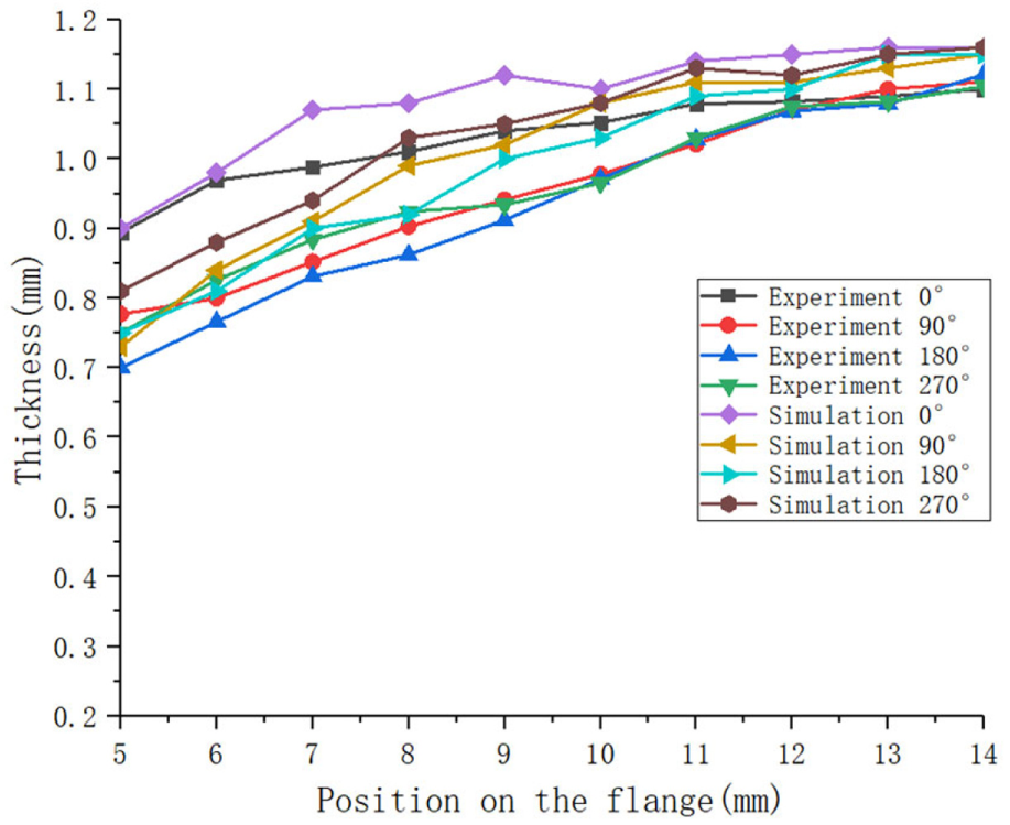
Thickness distribution of the flange.
Distribution of stress and strain
Stress field
The variations of the stress field with time are presented in Figure 12. Figure 12(a) shows that a small and uniform stress emerged on the outer surface of the workpiece without stress concentration and mesh distortion at the initial stage of spinning. When the forming process continued, a distinct ring stress belt appeared on the workpiece, as shown in Figure 12(b). The stress ring was collected inward with the spinning process. Before the end of the process, the stress was concentrated at the root of the flange, as shown in Figure 12(c). Although the stress was almost uniform in the 0°–360° direction on the flange, it was very uneven on the cylinder wall. A larger stress concentration occurred on the wall of cylinder in the 180° direction, as shown in Figure 13, due to the long-term and large-scale affection of the roller.
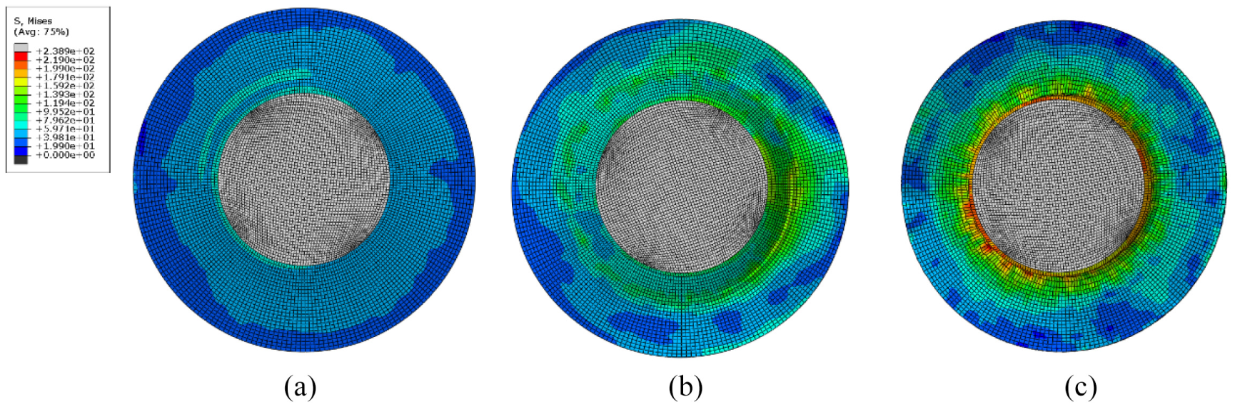
Variations of the stress field with a spinning time of (a) 20 s, (b) 40 s, and (c) 160 s.
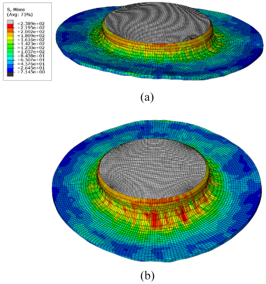
Stress distribution in the (a) 0° and (b) 180° direction.
Strain field
The variations of the strain field with time are presented in Figure 14. In Figure 14(a), a small-scale strain concentration occurred on the flange in the 180° direction due to the maximum axial displacement of the roller. The area with a bigger equivalent strain on the flange expanded as the forming process continued, as shown in Figure 14(b). Before the end of the simulation, the strain mainly concentrated in the root position of the flange, as shown in Figure 14(c). The largest deformation emerged on the junction of the flange and cylinder wall in the 180° direction, as shown in Figure 15. Therefore, this part was most likely to be broken.
Variations of the strain field with a spinning time of (a) 20 s, (b) 40 s, and (c) 160 s.
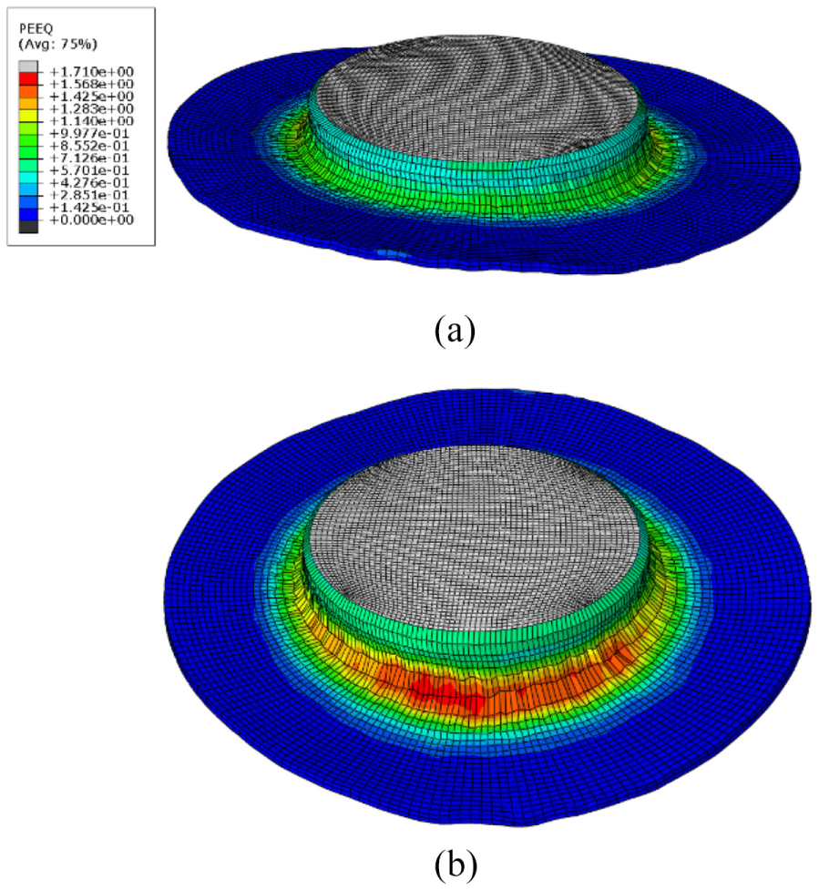
Strain distribution in the (a) 0° and (b) 180° direction.
Conclusion
The spinning process of a non-axisymmetric cylinder with an oblique flange was studied by simulation, and the credibility was verified by performing an experiment. The conclusions are summarized as follows:
According to the roller path boundary condition, the finite element model of the non-symmetric oblique flange cylinder spinning was established, and the accuracy of the finite element model was verified by spinning experiment. The geometrical appearance and wall thickness distributions of the simulation and experimental results were in good agreement.
The effect of parameters d and c on the formed shape was investigated through numerical simulation. A smaller d and c were beneficial in obtaining the straight-oblique flange.
The FEM of the multi-pass non-axisymmetric spinning described the quantitative relationship between the forming conditions and forming results by analyzing the variations of the stress field and strain field with time. This provides a basis for the forming and optimization of cylinders with an oblique flange shape by spinning.
Footnotes
Declaration of conflicting interests
The author(s) declared no potential conflicts of interest with respect to the research, authorship, and/or publication of this article.
Funding
The author(s) disclosed receipt of the following financial support for the research, authorship, and/or publication of this article: The work was supported by the Natural Science Foundation of Liaoning Province, China (no. 201602558), Aviation Science Foundation, China (no. 2018ZE54028), the Liaoning Provincial Department of Education Fund (no. L201748), the Open Foundation of Key Lab of Fundamental Science for National Defense of Aeronautical Digital Manufacturing Process (no. SHSYS2016001), and the Liaoning Province Students’ Innovation and Entrepreneurship Training Program Project (no. 201810143184). The authors wish to express their gratitude.