
Abstract
To satisfy rising flexibility and reconfigurability, the combination of system design and control software design has been adopted as a common paradigm for engineering manufacturing systems. However, there is still a lack of efficient approaches to automating the projection from the system design to the control software dimension. In this study, a model-driven approach is proposed to generate the control logic design based on the IEC 61499 Function Block from the system design in SysML. First, the system design model is formally defined to be unambiguously interpreted. Second, the SysML-FB profile is defined based on which control logic can be modelled in compliance with the IEC 61499 Function Block in the unified SysML modelling environment. Third, transformation rules between these two models are proposed, according to which a distributed event-driven control logic design can be automatically generated. This approach is implemented as a computer-aided design tool extended from the mainstream SysML modelling platform MagicDraw and illustrated using a computer numerical control bending machine as the case study.
Keywords
Introduction
Today’s manufacturing is facing the diversity and variability of customer requirements. 1 In response to the fast-changing consumer demands, manufacturing systems are required to be highly flexible and reconfigurable. 2 This challenge can be tackled by the next generation of distributed automation systems, 3 in which software is the key to increasing the level of intelligence of systems. However, in contrast to the central role of software in the systems, according to the traditional development approach, which considers the development of mechanical, electronic and software parts of the system sequentially, control software design normally has to be initiated after the design of mechanical and electronic subsystems has been finalized. 4 System design, which is one of the main activities in the systems engineering process, considers multi-disciplinary subsystems simultaneously in the early design stage 5 and hence can be adopted to solve this challenge. Based on system design, the common paradigm for developing manufacturing systems is changed such that the system design is generated first and then projected to the mechanical, electronic, software dimensions so that the detailed design of each discipline can be initiated. This idea has been adopted broadly, such as in general mechatronic system design 6 and manufacturing automation system design. 7 When the above-mentioned rationale is applied in the model-driven development (MDD) approach, 8 the involved artefacts should be represented as models, and the development process is driven by transformations between different models.
The focus of this study is the projection from the system design model to the control software dimension. Considering the main task of control software is to coordinate the physical resources in the manufacturing systems to achieve a specified manufacturing process; the control logic, which is the core concern of control software design, should be inferred from the system design. To this end, both the system design and control logic should be represented as models first; then, the automated transformation between these two models should be provided.
The first constituent of this work is the system design modelling method. SysML, which is the standard system modelling language, has been considered an appropriate candidate for this purpose by many researchers.4,9,10 However, since SysML is a general-purpose modelling language without any domain-specific modelling formalisms bound to it, the most proper domain-specific model elements for representing the manufacturing system design are not determined.
The second topic of this study is the control logic modelling. The control logic should be modelled in SysML as well to clearly show the traceability with and to be automatically inferred from the system design. Model elements in SysML should be extended based on certain existing domain-specific concepts for this purpose. IEC 61499-1 Function Block (FB) reference architecture, 11 which adopts the event-driven execution semantics for representing the distributed control logic in a platform-independent way, can be chosen as the basis. 12 This standard is conceived to support the design and development of distributed automation systems; thus, the distributed manufacturing system is one of the promising application areas of it. 3
The last but most important challenge to be investigated is the automated transformation between system design and control logic design models. This topic has been discussed in many works in the field of MDD of control systems. However, because of the considerable gap between these two models, existing methods either require the system design to be modelled in an IEC 61499-oriented way or rely on manual effort to accomplish this task.
In this study, an approach to automatically generate a control logic design from system design in SysML is proposed. First, the formal specification of the structure and process of manufacturing systems is defined, according to which the most proper elements in SysML are identified. Second, the SysML-FB profile is constructed such that the precise semantics of control logic can be modelled in SysML according to the IEC 61499 standard. Third, the essential correspondences between these two models are analysed, according to which the control logic can be automatically inferred from the system design.
The rest of this article is organized as follows. Related works are reviewed in section “Related works.” In section “System design model,” the proposed method for modelling system design in SysML is described. In section “Control logic design model,” the SysML-FB profile is defined. In section “Automated generation of control logic,” transformation rules for inferencing control logic models from system design models are formally defined and explained. In section “Implementation and case study,” implementation of the proposed approach is introduced, and a computer numerical control (CNC) bending machine is used as a case study to illustrate the workflow. Finally, the conclusion and future works are discussed in section “Conclusion and future work.”
Related works
Related works about the three topics discussed in this study are reviewed in this section.
System modelling in UML/SysML
Before SysML was proposed, UML was widely used to model systems for different purposes. Thimm et al. 13 proposed the Product Life-Cycle Unified Modelling Language (PLUML), which is a PLM-oriented derivative of UML for modelling a product’s life-cycle in a unique language. The advantages of UML including the unified syntax across stages and capability of describing systems from different views and levels of details were demonstrated in this research. Liu and Young 14 adopted UML class diagrams to represent information and knowledge structures to tackle the complexity of the information and knowledge types involved in global manufacturing decision-making. Burmester et al. 15 extended UML for modelling the hybrid, reconfigurable, mechatronic systems such that the modelling, verification and code generation could be seamlessly supported.
However, because UML essentially tends to be software-centric, adaptation is required when being used to describe systems that constitute multi-physics subsystems. Therefore, derived from UML, SysML is proposed to support specification, analysis, design, verification and validation of a broad range of systems. Various model elements and diagrams provided by SysML can be utilized to facilitate the thinking and communication of the engineers and the documentation of system design according to general model-based systems engineering (MBSE) 16 processes such as Harmony SE, 17 OOSEM 18 and SYSMOD. 19
However, considering SysML is a domain-independent modelling language, and it needs to be customized to facilitate the engineering of systems from different domains. To design and verify distributed industrial manufacturing control systems, Hirsch et al. 20 adopted SysML in the system specification stage for capturing requirements and building a consistent specification. Fan et al. 21 extended SysML to represent geometric information of the system structure, from which the initial computer-aided design (CAD) models could be automatically generated. Cao et al. 22 represented computational hybrid dynamic behaviour models of mechatronic systems in SysML, which can be transformed into executable simulation models.
These works show the powerful capability of SysML in modelling systems to support various tasks in the system development process. However, modelling methods specific to manufacturing systems should be investigated especially for the purpose of automated control logic generation.
Extending UML/SysML for control modelling in IEC 61499
Many researchers have investigated the possibility of extending UML/SysML for modelling the IEC 61499 FB-based control systems/applications. Batchkova and Antonova 23 proposed an approach to improving the software development life cycle, in which the compatible SysML elements are used directly to model the control systems. Zhang et al. 24 studied the FB paradigm and created an FB-specific profile to facilitate the specification of FBs and FB networks in UML. To describe the distributed control system considering the whole development process, Panjaitan and Frey 25 mapped the FB concepts to UML for high-level design and transformed the UML models to FB models for low-level design and implementation. Hussain and Frey 26 studied the structural and functional specification of the FB-based control application in UML. Dubinin et al. 27 defined the UML-based FB specification and its extension, in which the connections between FBs are analysed and classified.
The common drawback of these methods is that when taking full advantage of UML/SysML to represent the IEC 61499 FB, the subtle differences between the two languages were not analysed thoroughly. However, to obtain the precise semantics of FBs, it is necessary to extend or restrict UML/SysML modelling elements according to the analysis of the semantic and syntactic differences between them. Another weakness comes from the notations of the FB-related elements in the UML/SysML modelling environment. The FB-related elements inherit the notations of their parent elements in UML/SysML, which are not compliant with the IEC 61499 standard and hence are not intuitive to the engineers when being used to model the control applications.
Transformation between system design and control logic design
Some researchers have attempted to generate the IEC 61499 FB model from the FB-oriented system design model, among which the most significant work is the CORFU ESS. 28 It has been remarked as a first attempt to apply an MDD process in the analysis and early design phases of control applications. 29 In their control application development approach, requirements are first captured as the analysis model and then transformed to the FB-based design model. Since the whole process is FB-oriented, the mapping between the two models is straightforward. Two major differences from the approach proposed in this study are (1) the behaviour of FBs in their approach is directly given by the analysts in the form of state machines, whereas the key innovation of the proposed approach is the automated generation of control logic by reasoning on existing models; (2) since the main control logic is spread in different types of diagrams with redundant information, consistency between these diagrams must be manually maintained by the analysts. Panjaitan and Frey 25 and Dubinin et al. 27 introduced the automated transformation from the system specification in UML to the control application model in FB. However, in these approaches, since the UML model is already constructed according to the IEC 61499 FB standard using the proposed profiles, model transformation happens between different representations of the same concepts instead of concepts from different domains. The latter is the main challenge to be addressed in this study.
Some works are related to the model-driven engineering (MDE) of control applications/systems. Vogel-Heuser et al. 9 analysed the requirements for the MDE of manufacturing systems and proposed the SysML-AT profile to support the whole development lifecycle from requirement engineering to code generation based on IEC 61131-3. 30 Fay et al. 31 proposed an MBE approach for distributed manufacturing enhanced with characteristics and design patterns. Alvarez and colleagues32,33 presented a framework that implemented the MeiA methodology for the development of industrial automation systems. It provides not only detailed guidance to the developers through each development phases but also tools to generate the analysis and design artefacts, for example, automatically generating the skeleton control logic in IEC 61131 Sequence Function Charts (SFC) from Gantt charts. 34 These methodologies are mainly based on IEC 61131 and focus on guiding engineers to develop a system systematically instead of providing automated model transformation methods and tools.
Some studies specific to the process control engineering domain also covered the early design of control systems, for example, the approaches proposed by Hästbacka et al. 10 and Pang et al. 35 In their works, requirements are modelled according to the P&ID IEC 62424 standard; 36 then, corresponding component networks which realize the requirements are automatically generated via model transformations. Considering the specificity of this domain, these approaches cannot be applied to the distributed manufacturing system development.
System design model
To infer control logic, the most relevant information about a manufacturing system is its structure and manufacturing process. Considering various model elements are provided in SysML, the most proper ones to represent this information should be chosen. To this end, in this section, the information to be captured is formally defined as the system component model (SCM) and system process model (SPM). Based on the formal specification, the required model elements in SysML are identified.
SCM
The SCM captures the static structure of a system by modelling the abstract components of the system as well as their discipline-specific embodiment, that is, the mechanical, hardware and software components for the abstract components. This model is formally defined as
The sets MCI, MC, HCI and HC represent the mechanical and hardware components and their instances, whose definitions are similar to that of the software components above.
The concepts and relations in the definition of the SCM except the discipline-specific ones can be directly represented by the model elements in SysML. Specifically, the abstract components of the system are modelled by Blocks, and they can be instantiated to Part Properties of the system or other components via the Composite Association relationship, which indicates that the block on one end is an integral part of the block on the other end. The projection between the system components and the discipline-specific components is modelled by the Allocate relationship, which denotes the mapping of elements across different abstract levels, for example, associating the elements of the early design to the ones in detailed design in this case.
To illustrate the proposed approach, a simple conveyor system is used throughout the following sections. The system has one conveyor belt, which can be started, paused and stopped by operators via three buttons. The structure of the system is modelled by the SCM shown in Figure 1. Figure 1(a) shows the structure of the system, in which three blocks are defined to represent the conveyor system itself and the belt and button, respectively. The Belt and Button blocks are instantiated and added as parts of the Conveyor System, that is, belt, start, stop and pause. The software components identified by control engineers are modelled in Figure 1(b). The whole system is controlled by the Conveyor Control Application, which contains two controllers, that is, the Button Controller for controlling the three buttons and the Belt Controller for controlling the conveyor belt. These software components are modelled by FBs, which will be introduced in section “Control logic design model.” The allocations from the system components to the software components are represented in Figure 1(c).
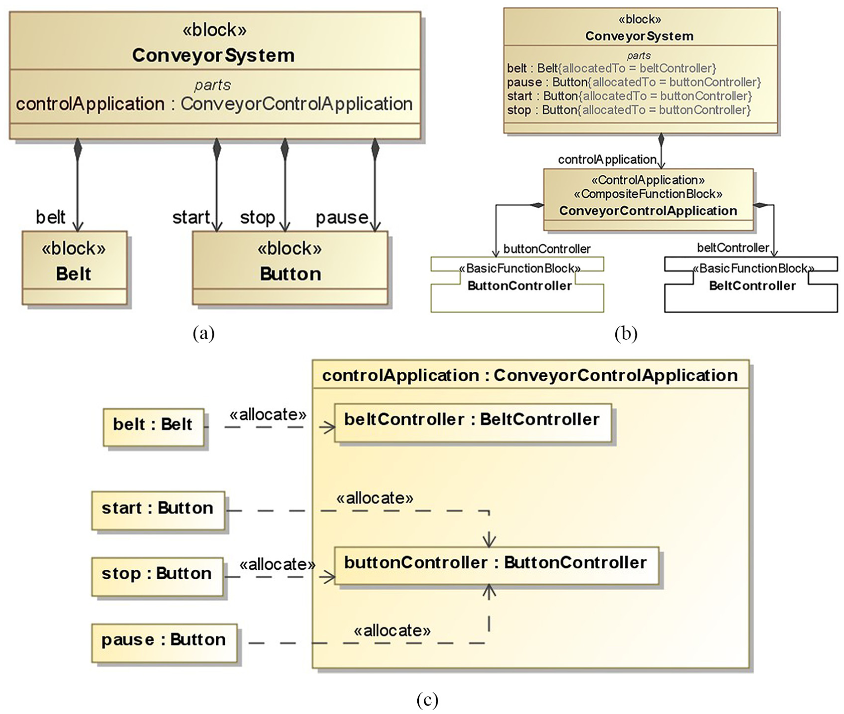
SCM of the conveyor system: (a) system structure, (b) control components and (c) allocations between system and control components.
SPM
In contrast to the SCM that captures the static structure of the system, the SPM captures the dynamic behaviour of the system. Specifically, it models the actions taken by the system in a certain sequence for achieving one use case. This model is formally defined as
The execution semantics of SPM is similar to the Activity Diagram (ACT) in SysML, except that the concept of the control token is explicitly modelled by signals. The basic idea is to model the execution sequence of the actions by passing signals between them through control flows. The source action generates a signal and offers it to its outgoing control flows. Then, the signal flows along the control flow to the target action. After that, the target action accepts the signal and invokes its own execution once all its required materials are ready.
For describing more complex logic, several special types of actions (so-called Control Nodes in SysML) are defined for better routing the signal flows. The semantics of these nodes are briefly introduced in the following:
The Initial/Final nodes mark the starting/stopping points of the whole process. Therefore, the Initial action cannot have incoming control flows and the Final action cannot have outgoing control flows.
The Fork node is defined to describe the concurrent execution of actions. It has a single incoming control flow with a signal and/or guard condition and multiple outgoing control flows without any signals or guard conditions. When the signal of the incoming control flow comes and the guard condition is evaluated to be TRUE, the signal will flow into all the outgoing control flows so that the target actions can be invoked concurrently.
The Join node has the opposite meaning from the Fork node. It routes several signals from multiple incoming control flows to a single outgoing control flow. When all the signals reach the target action, it will be invoked.
The Decision node has one incoming control flow with an associated signal and/or guard condition and more than one outgoing control flow with guard conditions only. When the signal passes through the incoming control flow, one of the outgoing control flows whose guard condition is satisfied will be chosen to carry the signal to the corresponding target action.
The Merge node is the counterpart of the Decision node and has more than one incoming control flow and exactly one outgoing control flow. Once a signal comes from any of the incoming control flows, the outgoing control flow will relay it to its target action.
Another special type of actions is the Accept/Send Signal actions, which are used to show the interaction between the system and external environment. The system can send signals to or accept signals from the external environment through the Send Signal and Accept Signal actions.
The above-defined SPM can be modelled based on the ACT of SysML. The actions and control flows can be modelled by Action and Control Flow, respectively. The control nodes can be indicated by the corresponding model elements in SysML. Signal is the only concept without appropriate model elements in SysML. For simplicity, a signal is denoted by the name of the control flow which carries it. The guard on the control flow can be modelled by the guard property of the Control Flow, whose value can be set as the Constraint representing a Boolean expression. The allocation from the action to the component instances can be modelled by the represent property of the Activity Partition. The Activity Partitions (so-called Swim lanes) divide the whole process to several regions, each of which represents a component instance. The actions included in each region should be executed by the corresponding component instance.
It should be noted that besides the model elements used in the SCM and SPM, other SysML elements can appear in the BDD and ACT. For example, the Input Pin, Output Pin and Object Flow can appear in the ACT to show the data flows between actions of a process. These extra elements are only for the purpose of documentation and communication between engineers but cannot be interpreted by the model transformation engine so far for generating control logic.
To illustrate the SPM, the essential use case of the conveyor system is discussed. In this use case, the operator changes the status of the conveyor belt by pressing different buttons. This use case can be described in detail by the SPM shown in Figure 2.
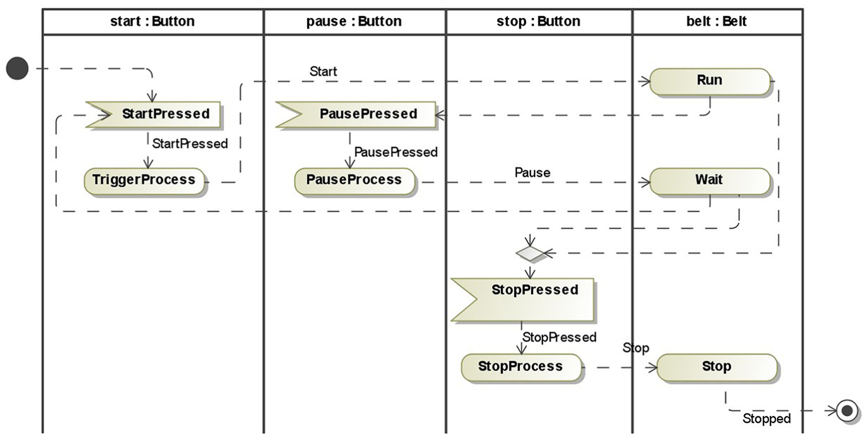
SPM of the essential use case of the conveyor system.
The whole process is partitioned into four regions. Each region is identified by the name and type of the corresponding component instance that executes the actions, for example, the first region belongs to the component instance start, whose type is Button. The process is triggered by the StartPressed signal that is received from the corresponding Accept Signal action. The signal represents the event that the operator presses the start button. When the signal is accepted by the start button, it will perform the TriggerProcess action to start the conveying process by sending the Start signal to the belt. The belt will execute the Run action after accepting the signal. When the pause button is pressed (indicated by the PausePressed signal accepted from the corresponding Accept Signal action), it will generate the Pause signal to the belt so that the belt will switch to the waiting status, represented by the Wait action. If the stop button is pressed (StopPressed signal is accepted) when the belt is either running or waiting, the Stop signal will be sent to the belt from the stop button so that the conveying process will be stopped by the Stop action. The Merge Node, shown as a diamond, is used to merge the two control flows from the Run and Wait action to the single flow towards the StopPressed action. After the belt is stopped successfully, it will send the Stopped signal, and then, the whole process is ended.
It should be noted that the process for creating the SCM and SPM is not determinate as illustrated in the above case. Actually, in real systems engineering processes, engineers normally first generate use cases from requirements and detail them by the SPM without specifying the partitions. Then, the components can be figured out by analysing the SPM so that the SCM can be built. After that, the actions in the SPM can be allocated to the constituents of the system so that the SPM is refined by the partitions. During this process, other types of models may be generated to document temporal design results or assistant information. In complex cases, the engineers will conduct this engineering process iteratively to optimize the models gradually.
Control logic design model
The IEC 61499 architecture provides the executable specification-level support for engineering of control systems. 37 It means engineers can rely on models to design and specify control systems on the high abstract level, as well as to implement and programme the applications on the code level. The former advantage of this architecture is taken to support the modelling of the early design of control logic.
The main artefacts of the IEC 61499 architecture are FB Types, which are the reusable building blocks of the control application encapsulating the control logic in an abstract way. The FB Types can be instantiated to FB Instances to constitute a control application. There are three types of FB Types: Basic FB Type (BFB) is the basic unit, which constitutes control applications or other complex FB Types for describing control logic by an event-driven state machine named an Execution Control Chart (ECC); Service Interface FB Type (SIFB) represents the interfaces of control applications through which the low-level services provided by operating systems or hardware can be accessed; Composite FB Type (CFB), composed of the instances of BFB, SIFB or CFB, enables the control application to be built in a hierarchical structure.
It can be seen from the standard that the control logic is mainly described by the ECCs of BFBs. The events referred in the ECCs are communicated through the event connections between BFBs which are contained in the FB networks of CFBs or control applications. The precise semantics of these concepts should be represented in SysML to facilitate the control logic modelling and design.
To this end, model elements for related concepts in IEC 61499 standard are created in SysML. Since SysML is a general-purpose modelling language, to define these domain-specific model elements, its extension mechanisms should be used. There are two extension mechanisms for SysML: the heavy-weight method that defines new meta-classes and the light-weight method that creates stereotypes by extending the existing constructs. Here, the latter is chosen for quick prototyping on existing SysML modelling platforms, such as MagicDraw used in this article. After analysing the semantic differences between the model elements of SysML and IEC 61499 FB, some stereotypes are defined with distinct notations provided. These stereotypes compose the SysML-FB profile, which is divided into four sub-profiles, that is, Common, BFB, CFB and SIFB. Details about the profile are introduced in following sections except the SIFB sub-profile since it is not relevant to control logic modelling. Note that some of the model elements are given IEC 61499 standard-compliant appearance as illustrated in section “Automated generation of control logic.” For example, the event ports are shown as blue rectangles on the upper boundaries of FBs.
Common profile
The three categories of FB Types share the same kinds of interface, that is, the Data Input, Data Output, Event Input and Event Output, through which the FB instances can be connected and interchange data and events between each other. The data are used as the input and output parameters of the control algorithms executed by the FBs, and the events are consumed or produced by the FBs to drive the execution of control algorithms. The data can be read from or written to the data interfaces by FBs only when certain events happen. Therefore, the With relationship is used to associate the event interfaces with the data interfaces to determine when the data are sampled.
The model elements for the above-mentioned concepts are defined in Figure 3. The four types of interfaces are modelled as stereotypes inherited from the Flow Port in SysML with these constraints: all the ports should be atomic, which means they can only be classified by a single Block or Value Type, and the directions of the ports should be consistent with those indicated by their names. The type of the ports denotes the item can flow through the ports, for example, Integer, Boolean for data ports and Event for event ports. Therefore, the classifier of the data and event ports should be Value Type and Event, respectively. The implicit semantics of the data and event ports is that the type of the ports specifies not only what can but also what does flow through the ports. Therefore, the specification of item flows on the connectors connecting these ports can be omitted. With relationship is extended from Dependency in UML with constraints on its client and supplier: With can only connect event ports and data ports with a consistent direction, that is, Data inputs and Event inputs or Data outputs and Event outputs.
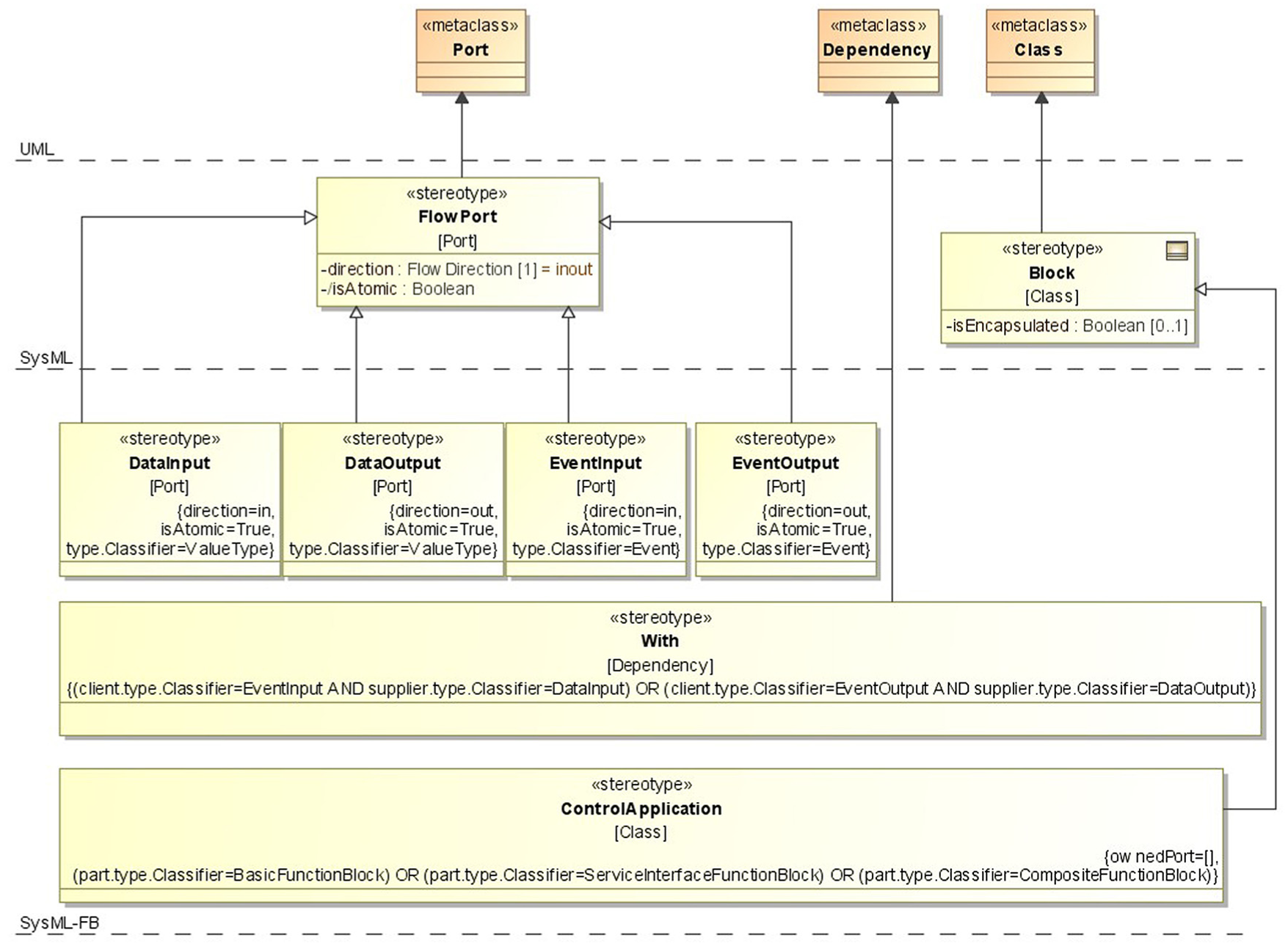
Stereotypes for common elements.
The last common element defined in this profile is the Control Application for representing the whole control application. Similar to the CFB defined in section “CFB profile,” it is a special type of Block which can have instances of BFB, SIFB and CFB as its inner parts and whose structure is described by the FB Network. The only difference from the CFB is that the Control Application cannot have ports. There are other properties associated with the control application in the IEC 61499 standard, such as mappings from the FB instances to hardware components, but they are not relevant to the design of control logic.
BFB profile
All three categories of FB Types are modelled by stereotypes extended from Block in SysML as shown in Figure 4. The particularity of Basic FB is that it can have Internal Variables described by Value Properties but cannot have an internal structure constituted by Part Properties.
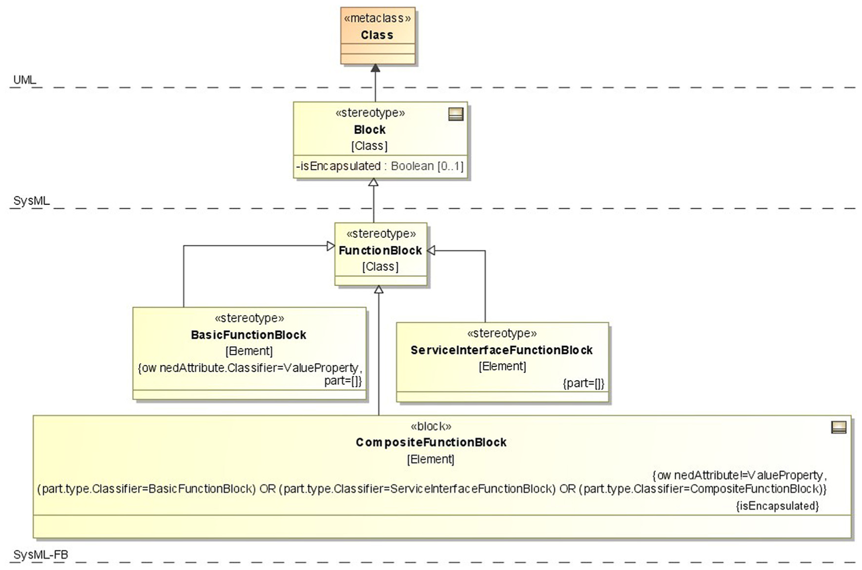
Stereotypes for FB types.
The behaviour of BFB is specified by the ECC, which is the cornerstone for implementing the event-driven execution mechanism. ECC is a finite automaton whose vertices and edges are typed as ECState and ECTransition. The execution semantics of ECC is roughly similar to that of the State Machine in UML/SysML. When an event is accepted by an BFB through its event input, the ECC of the BFB will evaluate all the outgoing ECTransitions of the current ECState and select the one which can be triggered by the event. There can be an ECCondition associated with the ECTransition to provide fine-grained control over its firing: only if the ECCondition associated with the selected ECTransition is satisfied, the transition will be fired and new ECState can arrive. Each ECState can be associated with zero or more ECActions, each of which contains an ECAlgorithm programmed in a certain language for describing the specific control logic and an Output Event for notifying the completion of the execution and updating the return values of the algorithm. The initial state of an ECC is always START, which is a special ECState without any ECActions.
As shown in Figure 5, the stereotypes for representing the ECC-related concepts are extended from the State Machine–related model elements in UML/SysML. ECC is a special StateMachine which only has one region with ECState and ECTransition as its vertices and edges, exclusively. Therefore, it is a ‘flattened’ state machine without any state hierarchy or pseudo-states, such as Join/Fork and Merge/Decision, to implement complex compound transitions. ECState is a simple State that does not contain sub-states. The START state is a special ECState that is also an initial Pseudostate. ECTransition is an external Transition with ECCondition as its guard. ECCondition, ECAlgorithm and OutputEvent are extended from Constraint and Comment accordingly. The ECAlgorithm is connected with its corresponding OutputEvent by the Dependency relationship such that the ECAction can be implicitly represented.
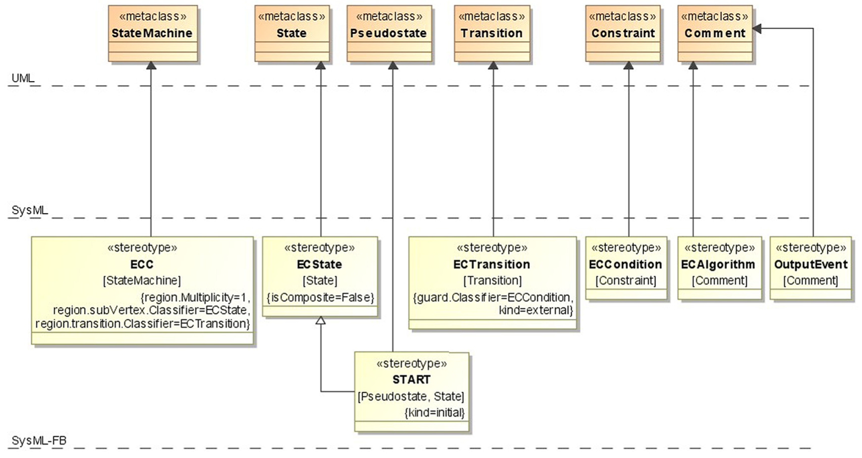
Stereotypes for representing ECCs.
CFB profile
CFB is defined for modelling the hierarchical structure of control applications. As shown in Figure 4, a CFB cannot have internal variables but can be constituted by instances of the BFB, SIFB and CFB. The behaviour of CFB is described by an FB Network that is constructed by FB instances contained in the CFB. The constituting FB instances of a CFB are connected by event or data connections through their event or data ports.
There is no appropriate model element to explicitly represent the FB Network, but the Internal Block Diagram (IBD) can be used to view it in SysML. All the FB instances constituting a CFB can appear on its IBD and be connected by Connectors such that the internal structure of the FB Network of the CFB can be presented.
One major constraint on the CFB is that, when it is instantiated and connected with other FB instances, its internal structure is not exposed publicly, which means the CFB is viewed as a ‘black box’ from outside. Therefore, the so-called transit connections 27 that cross the boundary of a CFB to connect to its internal FB instances are not allowed. This constraint is represented in SysML by setting the isEncapsulated tag of the CFB to be true.
Automated generation of control logic
As mentioned above, the core of the control logic design is contained in the ECCs. Therefore, how to distribute the centralized manufacturing process documented in the SPM in SysML to the ECCs of individual BFBs is the key issue to control logic design. To this end, the essential correspondences between the two models are analysed and summarized as heuristic rules first; then, according to the analysis, transformation rules are defined such that the ECCs described in the SysML-FB profile can be generated. Because events used in ECCs are sent/received through the event ports of BFBs, the ports and corresponding connections between them are also automatically generated.
Heuristic rules
By analysing and comparing the semantics of the system design in SPMs and control logic in ECCs, heuristic rules are identified such that the correspondences between the two models are extracted. These heuristic rules explain the basic idea and reasonability of the mapping between these two models.
Heuristic Rule 1
The actions except for the special control nodes of component x in the SPM are controlled by the algorithms executed in the ECStates of controller c that x is allocated to. Taking the conveyor system described in section System design model as an example, the component belt is controlled by the beltController according to the Allocate relationship described in the SCM. Since there is an action Run of the belt in the SPM, in the ECC of the beltController, there should be a corresponding ECState which executes the control algorithms for regulating the running process of the belt (e.g. keep it moving at constant speed). According to this rule, each of the normal actions of components should be mapped to one corresponding ECState in the ECCs of their controllers.
As mentioned in section “SPM,” there are six types of control nodes included in the SPM. The semantics of the Initial/Final nodes will be analysed in Heuristic Rule 5. The Merge/Decision and Fork/Join nodes are for routing the control flows without indicating any concrete control behaviour and hence will not be mapped to any ECStates.
The Accept Signal action is implemented by a controller by accepting the signal from its event port. This is the default behaviour of event ports of BFBs according to the IEC 61499 standard. Therefore, no ECState is needed to achieve this function. The Send Signal action is treated the same as the normal actions except that it only sends signals without executing any control algorithms.
Heuristic Rule 2
The signal carried by the incoming control flow of action a (including the signal generated by the source action of the control flow and the signal accepted from external through the Accept Signal action) triggers the incoming ECTransition of ECState s, where s is the corresponding ECState of action a according to Heuristic Rule 1.
In the above example, the action Run of belt should have a corresponding ECState, for example, named Run in the ECC of beltController. The control signal Start accepted from the incoming control flow of this action triggers its execution and hence triggers the ECTransition leading to the ECState Run.
Heuristic Rule 3
The signal generated by action a (including normal action and the Send Signal action) is generated by the ECAction executed in the ECState s, where s is the corresponding ECState of action a according to Heuristic Rule 1.
For example, the action TriggerProcess of the button start generates the signal Start and offers it through its outgoing control flow. This signal is actually generated by the buttonController that controls the button start. Therefore, to model the generation of this signal, the ECState corresponding to the action TriggerProcess should send out this signal by setting the Event Output of its ECAction to Start.
Heuristic Rule 4
When a control flow leaves an action belonging to component x, the controller c of component x stays in its current state until any action of x is triggered again.
For example, the PausePressed signal, which means that the pause button is pressed by the operator, will take the belt out of the Run action. However, the belt keeps running as controlled by the beltController in the ECState Run until the pause signal is generated by the pause button. Then, the beltController enters the ECState Wait (mapped from the Wait action of the belt), which makes the belt halt. As a result, when generating the ECC of BeltController, it is reasonable to draw an ECTransition triggered by pause event from the ECState Run to Wait in the ECC of beltController. The significance of this rule is to infer the ECTransitions between ECStates.
Heuristic Rule 5
The Initial and Final nodes of the SPM are shared by all the components. In real execution, the Final node implicitly leads to the Initial node such that the whole process can be restarted again.
As shown in Figure 2, the Initial and Final nodes of the SPM are not allocated to any component instance. Actually, they are the common starting and ending points of the behaviour of all the components if the logic contained in the SPM is split and allocated to these components. After the manufacturing process is ended on the Final node, it can be started again from the Initial node. Based on this observation, when generating the ECCs of the controllers, both the Initial and Final nodes are mapped to the identical ECState START of each controller.
Generation of ECCs
According to Heuristic Rule 1, some control nodes and special actions in the SPM derive no concrete control actions. Therefore, these elements need special treatment, which is described in sections “Heuristic rules” and “Special treatment to Fork/Join,” respectively. Other common actions and flows between these actions are transformed into the ECStates and ECTransitions to construct the ECCs.
The conveyor system described in section “System design model” is used as the example. The input of the generation process is the SCM and SPM shown in Figures 1 and 2. The purpose is to generate the ECCs of the two BFBs: BeltController and ButtonController.
Special treatment to Merge/Decision and Accept Signal
According to the explanation in Heuristic Rule 1, the Merge/Decision nodes and the Accept Signal action in the SPM cause no actions of the controller and hence can be omitted before transformation.
The simplification can be automatically done following the below procedures. The Merge node is omitted by leading its incoming control flows directly to the target action of its outgoing control flow (and vice versa for the Decision node). For example, there is a Merge node merging the two control flows from the Run and Wait actions to the single control flow leading to the StopPressed action in the SPM of the conveyor system. For simplification, they can be drawn as two control flows directly connecting the Run and Wait actions to the StopPressed action. The Accept Signal action can be omitted by connecting all the source actions of its incoming control flows to the target action of its outgoing control flows. For example, the StartPressed action can be omitted by connecting the Initial node and the Wait action directly to the TriggerProcess action by the control flows carrying the StartPressed signal.
To facilitate the introduction of the transformation rules and the generation process, the SPM is drawn as a graph by adding all the actions and control flows as nodes and edges, respectively, as shown in Figure 6. According to the formal definition presented in section “SPM,” this SPM is constructed by the following items: Action = {a0 = Initial Node, a1 = TriggerProcess, a2 = Run, a3 = PauseProcess, a4 = Wait, a5 = StopProcess, a6 = Stop, a7 = Final Node}; Signal ={s0 = Start Pressed, s1 = Start, s2 = PausePressed, s3 = Pause, s4 = StopPressed, s5 = Stop, s6 = Stopped}; CFlow = {f0 = (a0, s0, a1), f1 = (a1, s1, a2), f2 = (a2, s2, a3), f3 = (a3, s3, a4), f4 = (a4, s4, a5), f5 = (a5, s5, a6), f6 = (a6, s6, a7), f7 = (a4, s0, a1), f8 = (a2, s4, a5)}. The set BFB is defined to represent all the BFBs included in the SCM of the system. In this case, BFB = {fb0 = buttonController, fb1 = beltController}. The function
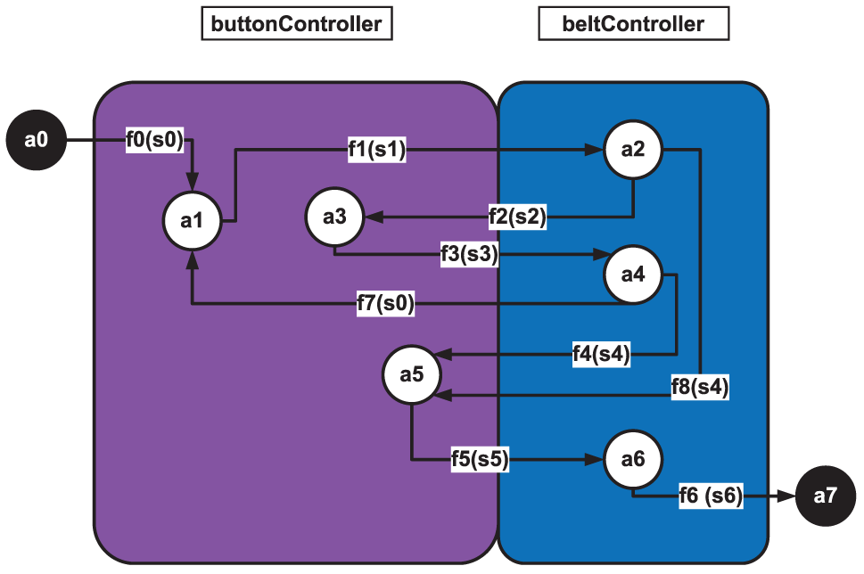
Formal representation of the sample SPM.
Transformation rules
The transformation rules for generating the ECCs are formally defined and exemplified in the following.
Rule 1.
Here, the notation ∀ stands for ‘for each’.
Rule 2.
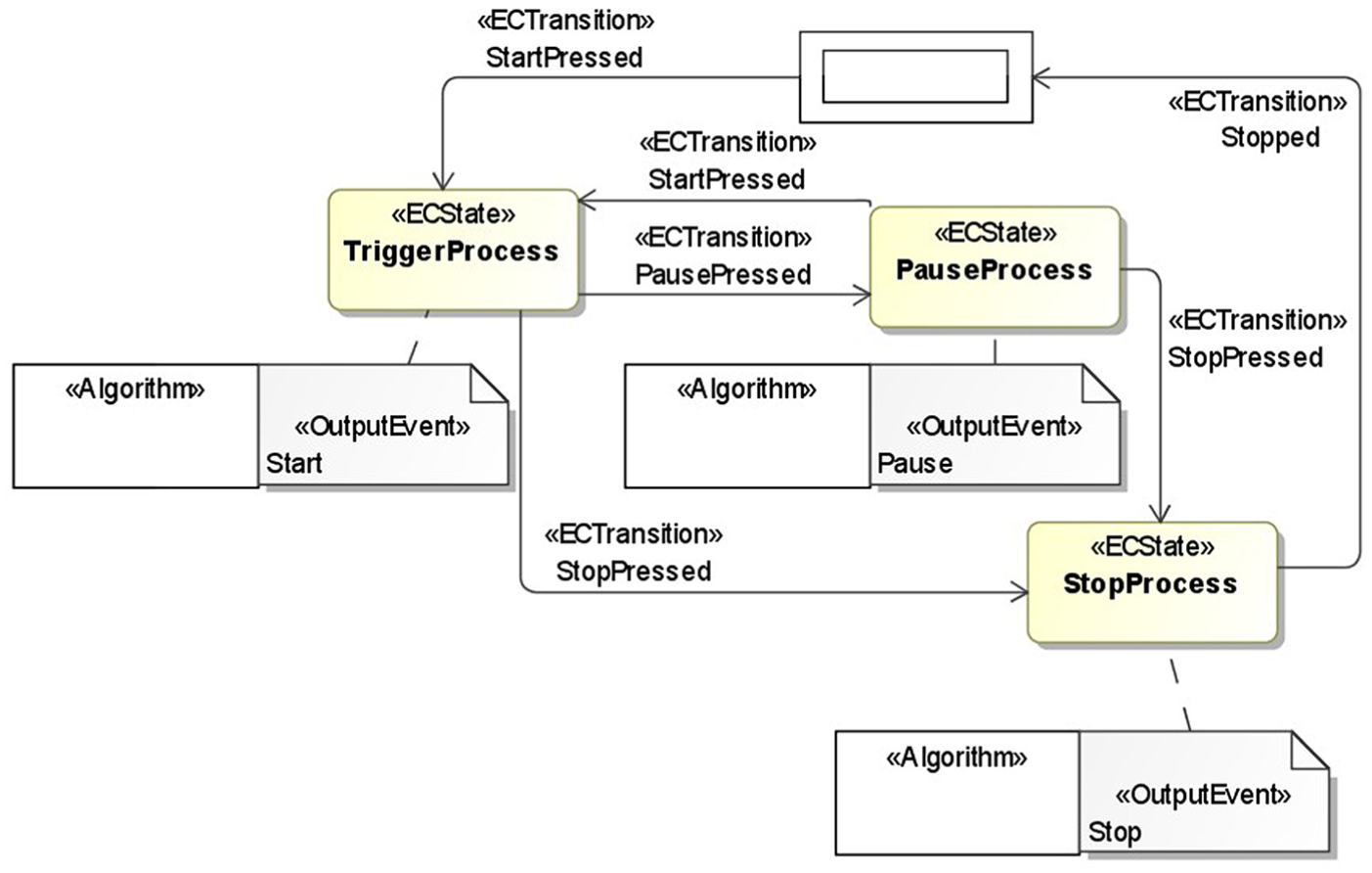
ECC of the button controller.
This rule is for adding the ECTransitions between the ECStates generated in Rule 1. Here,
The rule will first find all the actions (each of which is denoted by
Note that the Initial/Final Nodes follow the same rule as the normal actions. For example, there is a dpath between a5 and a7 which is (a5, a6, a7) so that there should be an ECTransition between s5: StopProcess and START (which the Final node maps to) triggered by Stopped sent from the beltController. The semantics of this ECTransition is that only when the belt is confirmed to be stopped can the buttonController go back to the START status and the start button be pressed again. Before that, no operation can be done by the operators.
After applying Rule 2, all the ECTransitions are added to the ECC as shown in Figure 7.
Rule 3.
This rule is for adding Output Events to ECStates. Here, the Out function finds all the outgoing control flows of the action
A special case when applying this rule is the signals generated by the Accepted Signal action. For such signals, they will not be mapped to Event Outputs. For example, the signal s0 = StartPressed is accepted from the external operator. Although it appears on the outgoing control flow f7 = (a4, s0, a1) of a4 = Wait, it will not be mapped to the Event Output of the ECState Wait, which is the corresponding ECState of a4, because it is not sent from the belt.
After applying Rule 3, the ECC of the ButtonController is completely constructed as shown in Figure 7.
Generation of event ports and FB networks
The Event Inputs and Outputs are generated from the ECCs of BFBs according to the semantics of IEC 61499 FB. According to this standard, the events triggering the ECTransitions should all come from the corresponding Event Inputs, and the Output Events sent by the ECActions of ECStates should all emitted through the corresponding Event Outputs. Rules 4 and 5 are defined for this purpose.
Rule 4.
Rule 5.
Here, t.trigger stands for the trigger event of the ECTransition t, and a. OutputEvent is used to find the Output Event of the ECAction a. The function EI and EO are mappings between the events used in the ECC and the Event Inputs and Outputs of the FBs.
One special case worth mentioning here is the control flow connecting two actions belonging to the same component instance. For such self-control flow, an Event Input and Event Output will be generated with the same name according to the transformation rules. However, it is invalid according to IEC 61499 standard that one FB has multiple event ports with the same name. To address this problem, the two events mapped from the same control signal are renamed as the signal name plus In and Out, respectively, and transferred through two event ports with distinguishable names.
After the event ports of the BFBs are determined, they can be instantiated and located on the FB Network of the CFBs or control applications they constitute. For example, the ButtonController and BeltController are instantiated as buttonController and beltController, respectively, to constitute the Conveyor ControlApplication as modelled in the SCM.
The connections between the BFB instances on the FB Network can be generated by traversing the control flows in the SPM according to below Rule 6.
Rule 6.
For each control flow
After applying Rule 6, the FB Network containing the buttonController and beltController can be constructed as shown in Figure 8.
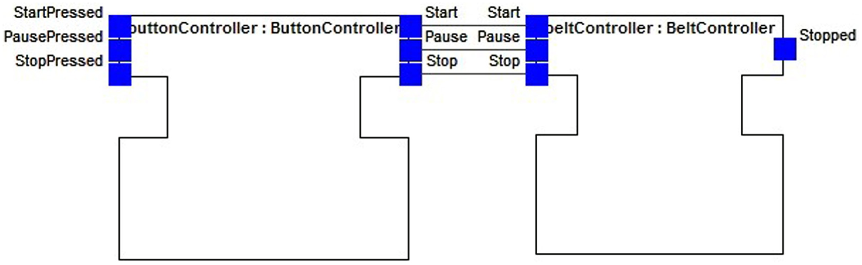
FB network of the conveyor control application.
The interfaces of the CFBs are determined by its constituting BFB instances and transit connections. If there is any transit connection c connecting the port
Special treatment to Fork/Join
Special attention needs to be paid to the Fork/Join nodes which describe the concurrent behaviours. Here, an excerpt of the SPM from the case study about the CNC bending machine illustrated in section “Implementation and case study” is used for explanation.
The system includes a processor to coordinate the behaviour of the cart and rotator, whose function is to convey and rotate the pipe to be manufactured according to the specified position y and angle b. The excerpt of the SPM including the Fork and Join nodes is shown in Figure 9. When the processor sends the signal TransferTriggered2, both the cart and rotator will start acting in parallel. After the specified position and angle are reached, the cart and rotator will notify the processor by sending the YReached and BReached signals, respectively. Then, the processor will continue the subsequent action TriggerBend.
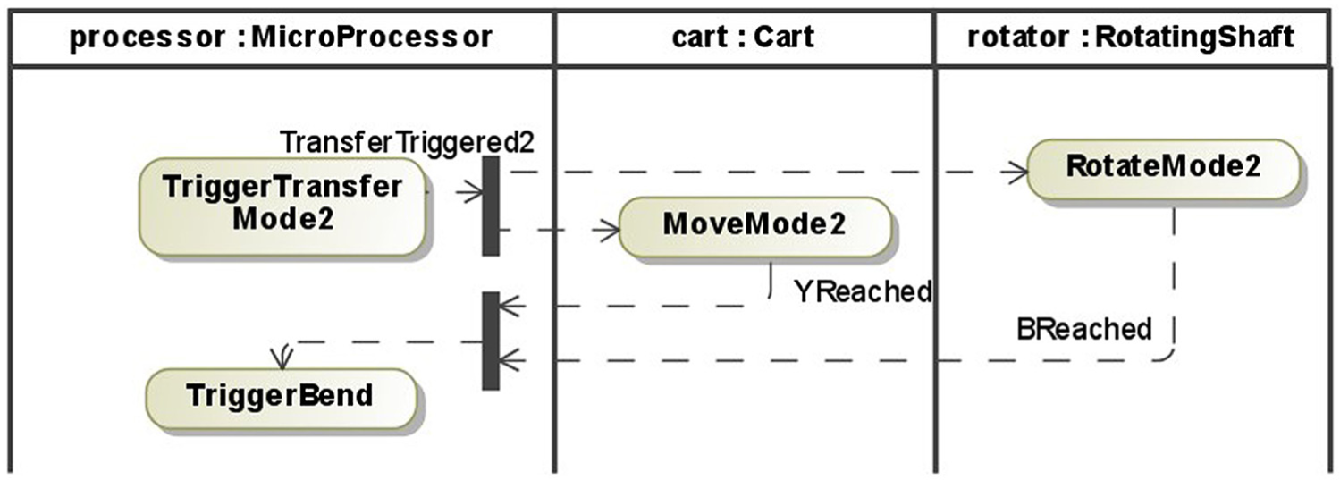
Sample SPM including Fork/Join.
The Fork node is treated similarly to the Decision node, except the multiple control flows are triggered by the identical signal and guard condition. In this example, the identical signal TransferTriggered2 triggers the two actions RotateMode2 and MoveMode2 such that the concurrency of the two actions can be guaranteed.
For the Join node, if its incoming control flows are triggered by the identical signal, it can be processed in the same way as the Merge node. However, if they are triggered by different signals, a new controller for synchronizing the two signals should be added because the ECC does not support the case that one ECTransition is triggered by multiple events according to the IEC 61499 standard. The synchronizer can be modelled by the Sync FB whose Event Inputs are mapped from the signals on the incoming control flows of the Join node, and the single Event Output represents the merged output signal. The ECC of the Sync FB can be generated by enumerating all the reaching sequences of the incoming signals. In this example, a new synchronizer component is added, which has a new action for synchronizing the two signals YReached and BReached to the identical signal YBSync. When this component is mapped to its controller Sync FB, the Event Inputs of the controller are YReached and BReached and the Event Output is YBSync. Its ECC is shown in Figure 10. The left sequence represents the case that the cart reaches the expected position (YReached reached the Sync FB first) before the rotator reaches the expected angle (BReached). The right sequence represents vice versa. Both paths lead to the Sync state in which the YBSync event is sent out.
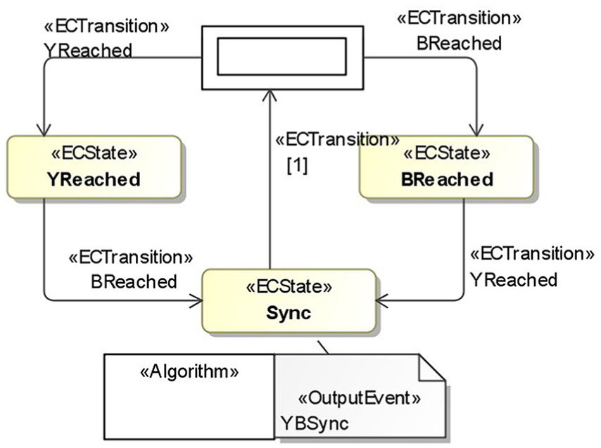
ECC of the Sync FB.
This reformulation is automatically done according to the above-mentioned principles. After reformulation, the SPM can be processed as normal by the transformation rules introduced previously.
Implementation and case study
The proposed approach is supported by the mainstream SysML modelling platform MagicDraw with two plugins that are developed by the authors to extend its functions. The FBModel Plugin is for defining and rendering the elements of the SysML-FB profile, and the FBAutoGen Plugin implements the model transformation engine for automatically generating the control logic design model in SysML-FB.
A CNC bending machine is used to illustrate the proposed approach. The major function of this machine is to bend the pipe according to the user-specified data indicating the expected shape of the pipe. The data are a three-dimensional array YBC whose length is the number of expected curves on the pipe. In the array, each element is a triple which specifies the expected location y, rotating angle b and bending angle c of each curve on the pipe. For simplicity, the diameter of each curve is fixed.
To achieve the function, some abstract components are identified and organized. The Cart, Rotating shaft and Jaw together compose the Transfer subsystem that is responsible for carrying the pipe to the specified location and rotating the pipe to the specified angle; the Clamp die and Bend die are the components of the Bend subsystem for bending the pipe. These mechanical components are actuated by the electric motors or pneumatic cylinders and supported by the position, angle or pressure sensors for detecting the status of the manufacturing process. The Microprocessor holds the programme for processing the pipe shape data and coordinating the behaviour of the two subsystems accordingly. Operators can interact with the system via the HMI.
The control application is designed in a fully distributed manner, according to which each of the mechanical components is controlled by an independent controller represented by BFBs. All of these low-level controllers are coordinated by the Central controller located on the Microprocessor. There is also a control programme for the HMI. For constructing the control application in a hierarchical way, the two CFBs Transfer Controller and Bend Controller are defined, which contain the basic controllers of the Transfer and Bend subsystems, respectively. The definition of the control application is shown in Figure 11.
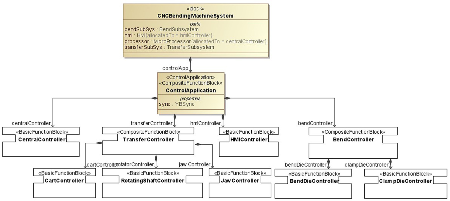
Control components of the CNC bending machine.
The SPM of the normal bending process is shown in Figure 12. The whole manufacturing process starts when the operator inputs the shape data about the curves to be produced on the pipe and presses Start via the HMI. For each curve specified in the shape data, the operator can select the mode that determines whether the cart and rotator work in sequence (mode1) or in parallel (mode2) when transferring the pipe. After the process is started, the processor will process the shape data and determine whether there is any curve to be manufactured. For each curve, the process will first trigger the jaw to fix the pipe on the cart and then identify the mode for transferring the pipe. According to the specified mode, the processor will trigger the actions of the cart and rotator to transfer the pipe to the specified location and angle. After the pipe is successfully transferred, the processor will trigger the bending process by telling the clamp die to fix the pipe and jaw to loosen the pipe such that the bend die can start bending the pipe without being followed by the cart. After the pipe is bent successfully, the clamp die will loosen the pipe and the bend die will be reset. Then, the processor will be notified about the completion of the manufacturing process for this curve and continue to process the next one if there is any.
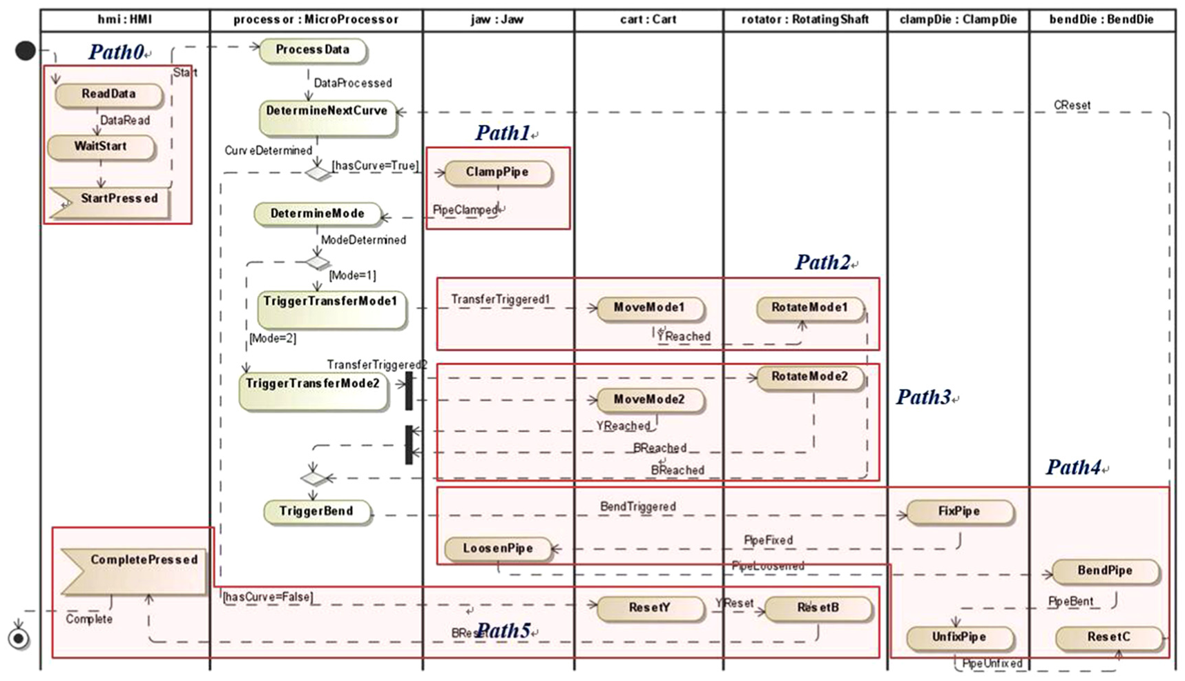
SPM of the normal bending process.
The CentralController, which is the most complex BFB in the system, is taken as an example to show the automated generation of ECCs. Actions of other components in the SPM are folded into the five paths as shown in Figure 12 for conciseness of the diagram. Based on the SPM, the ECC of the CentralController can be automatically generated as shown in Figure 13. To keep the model concise, the ECAlgorithms are hidden.
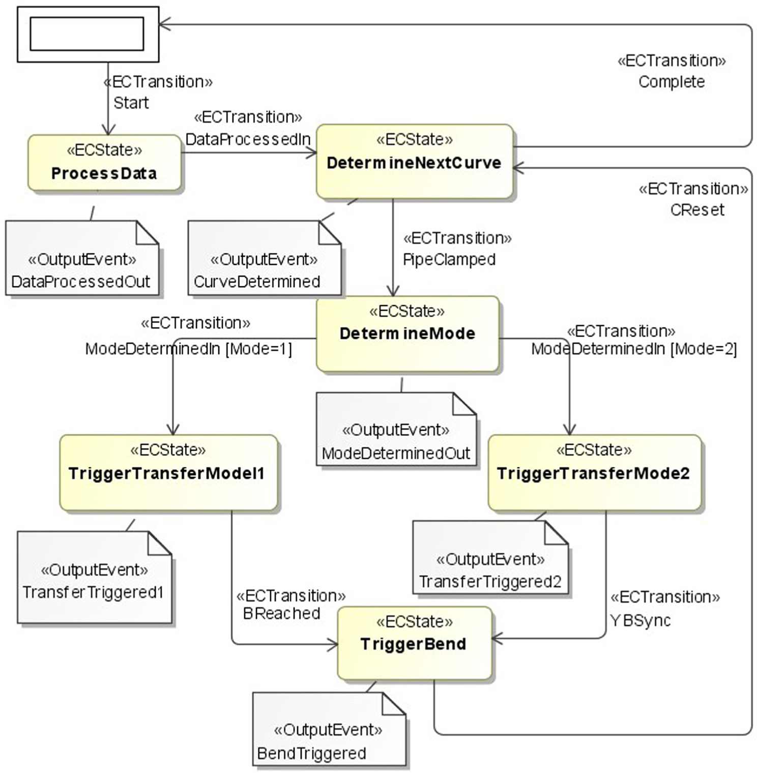
ECC of the central controller.
After the ECCs of all the BFBs are generated, the event ports of the BFBs are identified. Finally, these BFBs are connected together to construct the FB network of the whole control application in a hierarchical manner. The two CFBs, that is, TransferController and BendController, are connected in the top layer, and their constituting controllers are connected to construct them in the next layer.
After the skeleton control logic design is generated, engineers can continue to improve the design in the SysML modelling environment, that is, MagicDraw manually, or export the design into the FB development environment, for example, FBDK 38 and 4DIAC, 39 to start the detailed design and implementation, which control the concrete positions of the devices on each axis following certain algorithms, such as Davis et al. 40 Because the control application is modelled in SysML-FB, which follows the IEC 61499 FB standard strictly, the exporting process can be easily implemented. A tool based on the model transformation framework ATL 41 is developed. Figure 14 illustrates the exported FB model of CentralController in 4DIAC.
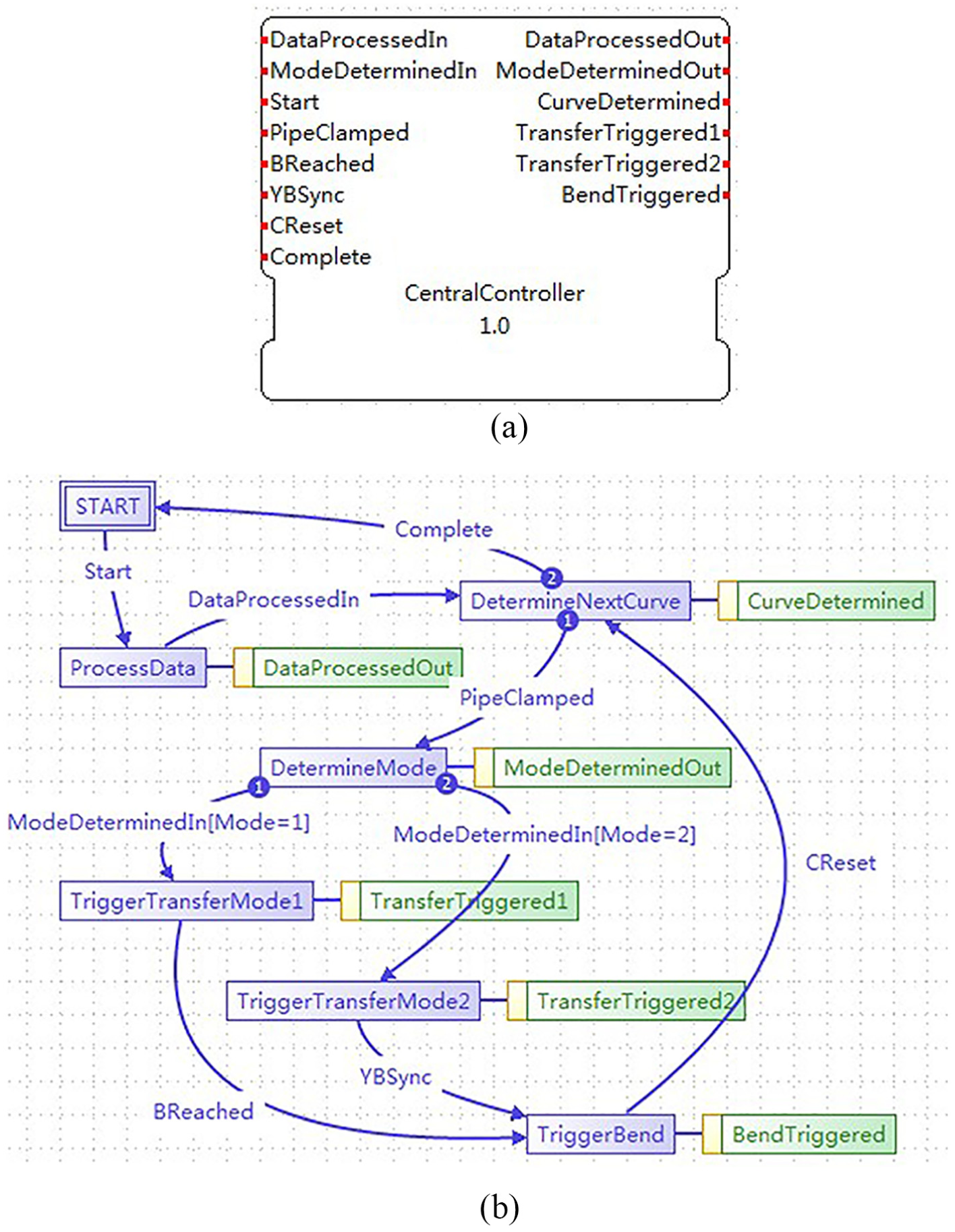
Central controller in 4DIAC: (a) BFB of the central controller and (b) ECC of the central controller.
Conclusion and future work
The generation of control logic from system design is a dispensable step in the MDD of control software of manufacturing systems based on system design. In this study, an approach to automatically infer the control logic model in IEC 61499 FB from the system design model in SysML is proposed. The whole process is realized in a mainstream SysML modelling platform, MagicDraw, enhanced by plugins developed in this study. System design models, including the SCM and SPM, are created by users manually. Then, from these models, the control logic model, including the FB network and ECCs of each FB constructing the network, is automatically generated and represented by notations defined in the SysML-FB profile by the plugins. A standalone tool is developed to export the generated SysML-FB models into the IEC 61499 FB development platform 4DIAC for the subsequent control-domain-specific development.
The main contributions are summarized as follows.
A method for modelling the structure and manufacturing process of the manufacturing system in SysML is proposed. Because of the formal definitions of the identified model elements, the information in system design relevant to control logic generation discussed in this study can be represented unambiguously.
The SysML-FB profile is defined, which supports the modelling of IEC 61499-based control logic in SysML. It is a foundation for the traceability between the control and other domains and the generation of control logic design from system design.
The essential correlations between system design and control logic design are analysed, according to which the skeleton control logic design model can be inferred according to the proposed transformation rules.
The limitations and corresponding future works are as follows.
In this study, only the event-driven control logic is generated. Although it is the core of the control software of manufacturing systems, other constituents, such as data-related aspects, including data ports and data connections, should also be taken into consideration to complete the control application model.
Currently, the approach only consumes a single manufacturing process as its main source. However, the manufacturing processes may be flexible or even reconfigurable. 42 These multiple sources should be considered and merged without conflicts when inferring the control logic.
The ultimate goal and motivation of this research is to support the synergetic development of multi-disciplinary subsystems based on the models generated from the systems engineering process. Therefore, besides projecting the system models to the control dimension, other dimensions, including the mechanical and electronic disciplines, should be considered.
Footnotes
Declaration of conflicting interests
The author(s) declared no potential conflicts of interest with respect to the research, authorship and/or publication of this article.
Funding
The author(s) disclosed receipt of the following financial support for the research, authorship, and/or publication of this article: This work was supported by the National Key Technology R&D Program (No. 2018YFB1700901) and the National Science Foundation of China (61873236, 61672247 and 61772247).