
Abstract
To study the surface forming mechanism of the solid–liquid two-phase abrasive flow processing, the large eddy simulation method was used. Taking a 90° stainless steel elbow as the research object, the action mechanism of the dynamic pressure, wall shear force, flow state of the abrasive flow at different cross-sections, formation of the vortex, and trajectory of the abrasive flow on the inner surface of the elbow with abrasive flow composed of solid-phase silicon carbide and liquid-phase hydraulic oil are discussed. This study explores the distribution characteristics of the flow pattern of solid–liquid two-phase abrasive flow. Moreover, the wear and erosion of the abrasive grain and the wall of the workpiece are discussed. The mechanism of surface formation of solid–liquid two-phase abrasive flow is revealed.
Introduction
Pipes are important components in modern industry. Owing to their special working environments such as in the medical, food processing, and aerospace fields, they often require high surface quality. A surface polishing treatment must be conducted to improve the surface finish of the pipe.1–3 However, with traditional surface polishing technology, it is difficult to fully finish the inner surface of the pipe. Traditional precision machining methods include electric discharge machining (EDM) 4 and electrochemical micromachining 5 , while abrasive flow machining (AFM) technology is an unconventional finishing process. It was developed by Extrude Hone Corporation, a US company in the 1960s, 6 which can be used to deburr, round, and polish.7–9 Its basic working principle is to squeeze the slurry with special rheological properties to flow through the closed flow path bounded by the fixture and the workpiece, and an inner surface with high precision can be obtained under micro-cutting.10–12 While processing, the abrasive grains are used as numerous micro-cutting tools, and the material is removed under the reciprocating action of the abrasive particles. 13 In addition to ordinary stainless steel materials, it can also process ceramics, semiconductors, quartz, and other materials. 14
Junye used molecular dynamics simulation software LAMMPS to simulate the cutting of single crystal copper with SiC at different cutting angles
In order to reveal the action mechanism of abrasive flow polishing elbow, the large eddy numerical simulation method is introduced to study the action law of abrasive flow polishing 90°elbow. By discussing the collision wear and erosion of the abrasive particles in the vortex region and the wall surface of the workpiece, the flow state of the abrasive flow at different cross–sections, and the formation of vortices and the surface forming mechanism of the abrasive flow polishing pipe is clarified.
Principle of LES
In the process of turbulent flow, the turbulent kinetic energy chain can be divided into large-scale and small-scale pulsations, in which large-scale pulsation contains almost all the turbulent kinetic energy, and small-scale pulsation is mainly dissipative turbulent kinetic energy.26,27 Since the LES eliminates the direct calculation of small-scale pulsation, the duration of the numerical simulation and the step size of the space can be amplified; thus, it can solve the problem of insufficient computational resources and reduce the computational workload. 28
According to the theory of LES, it is necessary to separate the large-scale pulsation (solvable-scale turbulence) and small-scale pulsation (sub-grid scale turbulence) for numerical simulation. The separation of the turbulence solvable scale and the sub-grid scale is called filtration. 29
For the LES of incompressible turbulence, it is assumed that the filtering process and the derivative operation are exchangeable, and the Navier–Stokes equation is filtered to obtain equations (1) and (2) 30
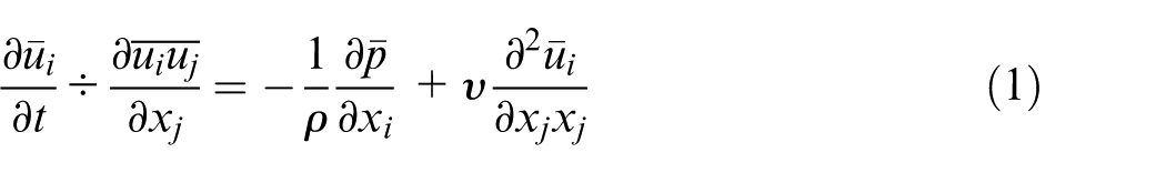
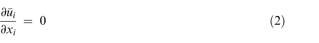
where “—” is large-scale component, ui is velocity, p is pressure, v is viscosity coefficient, ρ is density, t is time, and i, j, and k represent space coordinates xi, xj, and xk, respectively.
Let
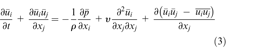
Equation (3) has a similar form to the Reynolds equation, and the right-hand side contains a non-closed term, then equation (4) can be obtained as

where
Establishment of numerical model of elbow
To study the LES of abrasive flow polishing pipe, the 90° pipe used in the project is selected. Figure 1 shows the three-dimensional (3D) model of the pipe. For convenience of description, the elbow is divided into several parts, as shown in Figure 2. The material of the elbow is stainless steel, the inner diameter is 8 mm, and wall thickness is 1 mm.
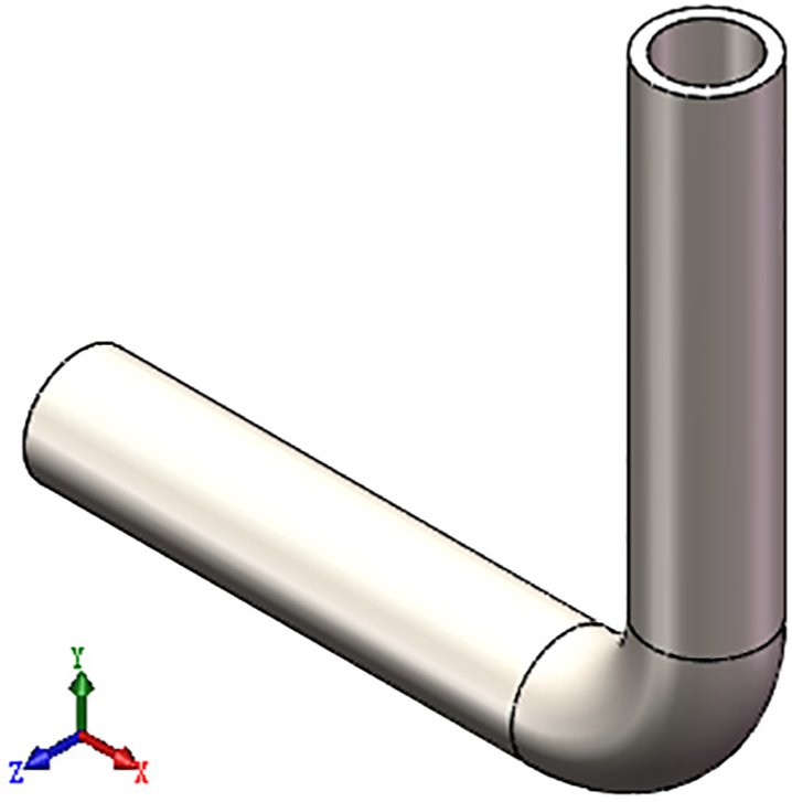
Three-dimensional solid model.
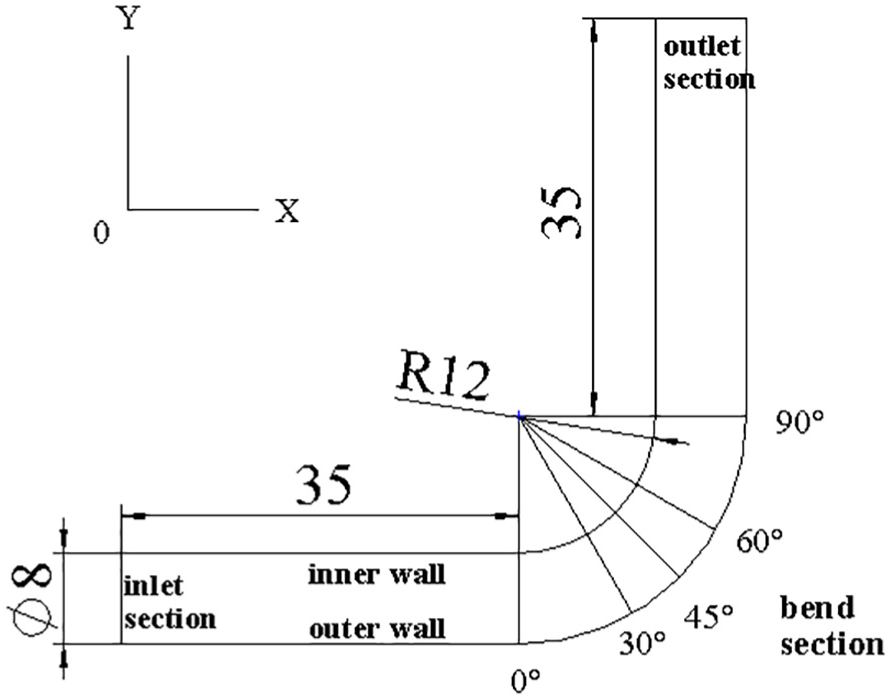
Schematic diagram of 90° pipe bend.
Boundary conditions
In order to accurately analyze the numerical simulation of the abrasive flow on the machined runner, the FLUENT software (version 15.0) developed by the ANSYS Corporation in the United States is used as the computing platform. The 3D double-precision detached solver was used, and Euler multiphase flow model mixture combining LES turbulence model was adopted. As for the spatial discretization, the bounded central difference format was used for momentum, the first-order wind was used for volume fraction, and the PRESTO scheme was used for the pressure correction equitation correct. Moreover, the pressure–velocity coupling for semi-implicit method for pressure linked equations-consistent (SIMPLEC) algorithm is selected. Hydraulic oil was adapted for fluid phase and silicon carbide, whose volume fraction is 25%, for particle phase in solid–liquid two-phase flow. The inner diameter of the pipe is 8 mm, and the kinematic viscosity of the abrasive particles is 38 mm2/s at a temperature of 40°C. According to the Reynolds number formula, the turbulent flow conditions can be satisfied when the flow velocity of the abrasive particles is greater than 20 m/s.
Results and discussion
Analysis and discussion of flow mechanism of abrasive grain flow in elbow
Combined with the actual abrasive grain polishing characteristics, the numerical simulation of the abrasive flow polishing pipe was carried out at an inlet speed of 30 m/s. The dynamic pressure distribution in the axial cross-section is calculated, and the pressure distribution at different cross-sections of the bend section is shown in Figures 3 and 4.
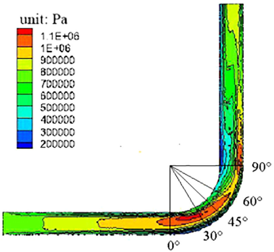
Axial section dynamic pressure distribution cloud.
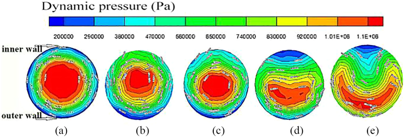
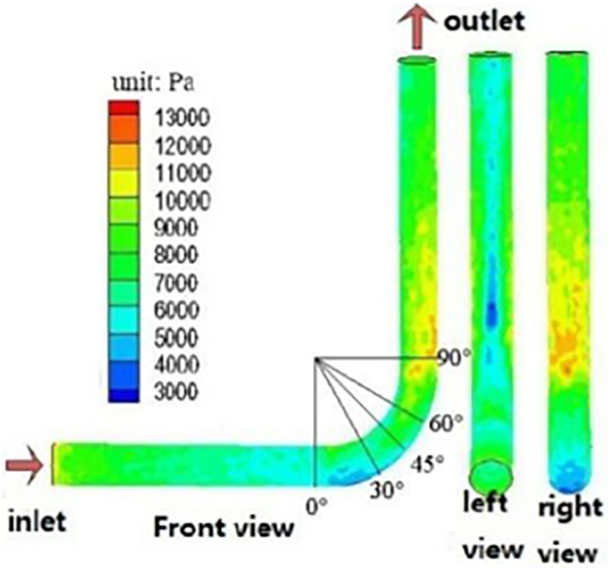
Contour maps of dynamic pressure in bend section for different cross-sections: (a) 0°, (b) 30°, (c) 45°, (d) 60°, and (e) 90°.
In the dynamic pressure cloud diagram in Figure 3, each color represents an order of magnitude, increasing from blue to red, and the color representation is consistent for all simulation images in this article. When the abrasive flow enters the pipe through the inlet, the dynamic pressure decreases stepwise in the inlet section. In the bending section, the dynamic pressure changes drastically and is significantly greater than the dynamic pressure of the inlet section. The dynamic pressure in the 0°–30° region near the inner wall is larger than that near the outer wall, and the polishing effect on the inner wall is greater than that on the outer wall. In the 45°–90° region of the bend section, the dynamic pressure near the outer wall is greater than that near the inner wall, and the polishing effect on the outer wall is greater than that on the inner wall. The abrasives in the bend section collide with the wall, and the abrasive flow is subjected to centrifugal force, such that the turbulence phenomenon is more obvious with abrasive flow from the bend section into the outlet section. Thus, the dynamic pressure in the outlet section is more chaotic, and the polishing effect on the outer wall is greater than that on the inner wall.
As shown in Figure 4, when the abrasive flow enters the bend section (0° cross-section), the dynamic pressure distribution is uniform around the circumference and is the largest in the central region. In the 30° cross-section, the dynamic pressure of the inner wall is greater than that of the partial lateral wall surface. The core region in the 45° cross-section begins to move toward the outer wall. The dynamic pressure of the outer wall in the 60° and 90° cross-sections is greater than that of the inner wall, and these cross-sections exhibit a significant low-pressure zone on the inner wall. In order to analyze the flow state of the abrasive flow in different cross-sections of the bend section, the velocity distribution of the abrasive flow and the flow pattern are shown in Figure 5.
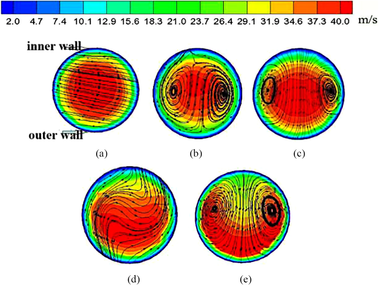
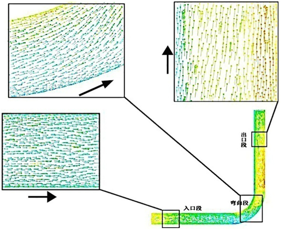
Velocity distributions and flow patterns for different cross-sections of the bend: (a) 0°, (b) 30°, (c) 45°, (d) 60°, and (e) 90°.
In Figure 5, the background color indicates the velocity distribution of the abrasive flow at different cross-sections, where the lines represent the trajectories of the abrasive flow in the direction of the cross-section of the elbow. Because the entrance to the 0° cross-section is vertical, and the abrasive flow is not subjected to a secondary force, its trajectory is a straight line. As the abrasives flow into the bend section, they collide with the wall under the simultaneous action of centrifugal force and axial movement of the pipe, and there will be sub-speed. A double swirlpool phenomenon occurs in the 30° and 45° cross-sections. The swirlpool of the elbow area does not always exist for flow through the 60° cross-section. Due to the existence of low pressure on the internal wall, the abrasive flow collapses under the pressure of the swirlpool, caused by changes in flow direction. From the flow in the circumferential direction to the inner wall of the flow, and the inner wall surface radial impact, it is clear that the 60° cross-section of the abrasive flow of the polishing effect differs from other cross-sections. When the abrasive flow and the inner wall impact each other due to the role of the reaction, whirlpool is re-formed in the 90° cross-section. The velocity vector and flow pattern of the abrasive flow in the elbow are shown in Figures 6 and 7, respectively.
Velocity vector of the abrasive flow in the elbow.
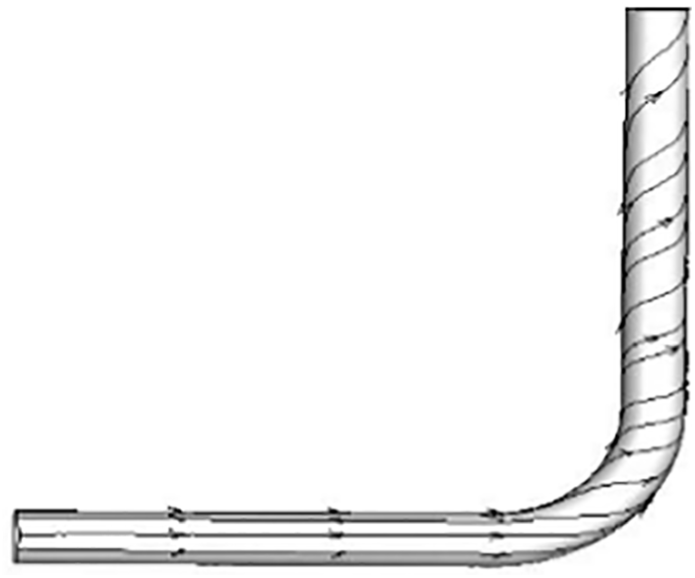
Flow pattern of abrasive flow in the inner wall of the elbow.
Figure 6 shows the abrasive flow velocity in the elbow, where the velocity direction in the inlet section is parallel to the axis. When the abrasive flow enters the bend section, swirlpool flow occurs in the cross-section, and the swirlpool moves the fluid from the inside to the outside surface of the pipe. Owing to abrasive flow in the elbow, the mainstream movement remains along the axis; thus, the whirlpool and the movement of the mainstream flow makes the abrasive flow spiral. As can be seen from the flow pattern of abrasive flow at the inner wall of the elbow in Figure 7, the abrasive flow in the inlet section is horizontal, parallel to the axis, and begins to move from linear flow to helical flow at the bend section. Figure 8 shows the distribution of wall shear forces obtained by the numerical simulation.
Wall shear force distribution: (a) inlet velocity v = 25 m/s, (b) inlet velocity v = 30 m/s, (c) inlet velocity v = 35 m/s, and (d) inlet velocity v = 40 m/s.
It can be seen from Figure 8 that the wall shearing force is larger when the abrasive flow just enters the elbow, because the outlet of the abrasive cylinder is larger than the diameter of the elbow, and the abrasive and the wall surface can be sufficiently contacted to cause an increase in wall shear force. In the inlet section, the wall shear force is relatively decreased. Due to the intense friction between the abrasive and the wall surface, part of the kinetic energy is converted into cutting energy, which leads to the reduction of wall shear force. In the bend section, due to the sudden change of the path, the abrasive flow and the wall surface violently collide, causing the wall shear force to rise sharply. In addition, the abrasive flow is subjected to centrifugal force when passing through the bend section. In the 30°–90° region of the bend section and the outlet section, the outer wall shear force is greater than the inner.
Dynamic pressure distribution at different inlet velocities
To verify the applicability of the morphological analysis of the abrasive flow in the 90° elbow, the flow patterns of the abrasive grains in the elbow were analyzed at four different inlet velocity conditions, v = 25, 30, 35, and 40 m/s. The dynamic pressure distribution of the 90° elbow under different polishing speeds is calculated by numerical simulation, as shown in Figure 9.
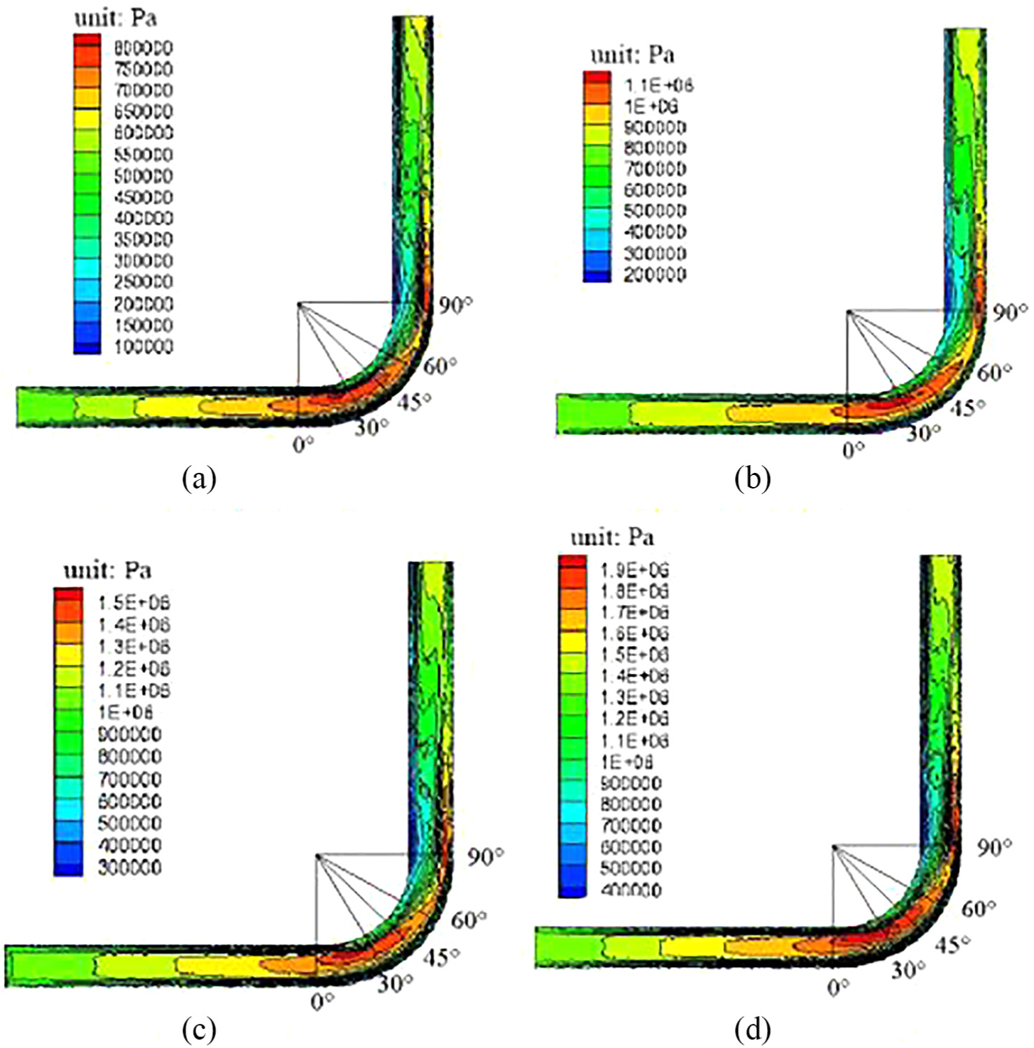
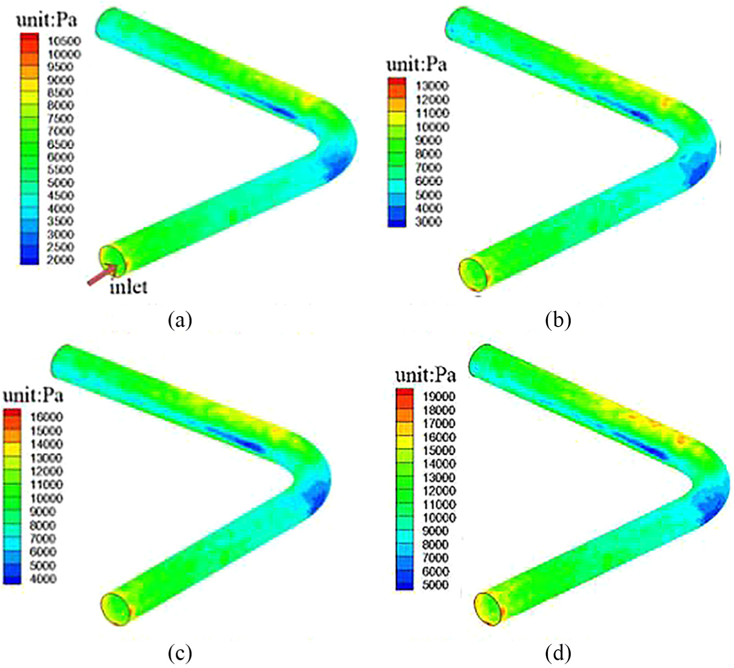
Dynamic pressure distribution at different inlet velocities: (a) v = 25 m/s, (b) v = 30 m/s, (c) v = 35 m/s, and (d) v = 40 m/s.
Figure 9 shows the dynamic pressure distribution at different inlet velocities. The abrasive flow in the elbow has a similar flow distribution in the inlet, bend, and outlet, across all inlet velocities. However, in contrast to the dynamic pressure numerical simulation at different inlet velocities, the dynamic pressure of the abrasive flow in the pipe increases as the polishing velocity increases. In addition, the dynamic pressure increase in the bending section is the most obvious, so that the impact of the abrasive on the wall of the elbow intensifies, and the impact of the more violent degree of confusion is greater. In the outlet section of the dynamic pressure distribution, the degree of confusion also showed an increasing trend. Figures 10 and 11 show the wall shear forces at the inlet speed and the dynamic pressure distribution at the 90° cross-section of the bend.
Wall shear forces at different inlet velocities: (a) v = 25 m/s, (b) v = 30 m/s, (c) v = 35 m/s, and (d) v = 40 m/s.
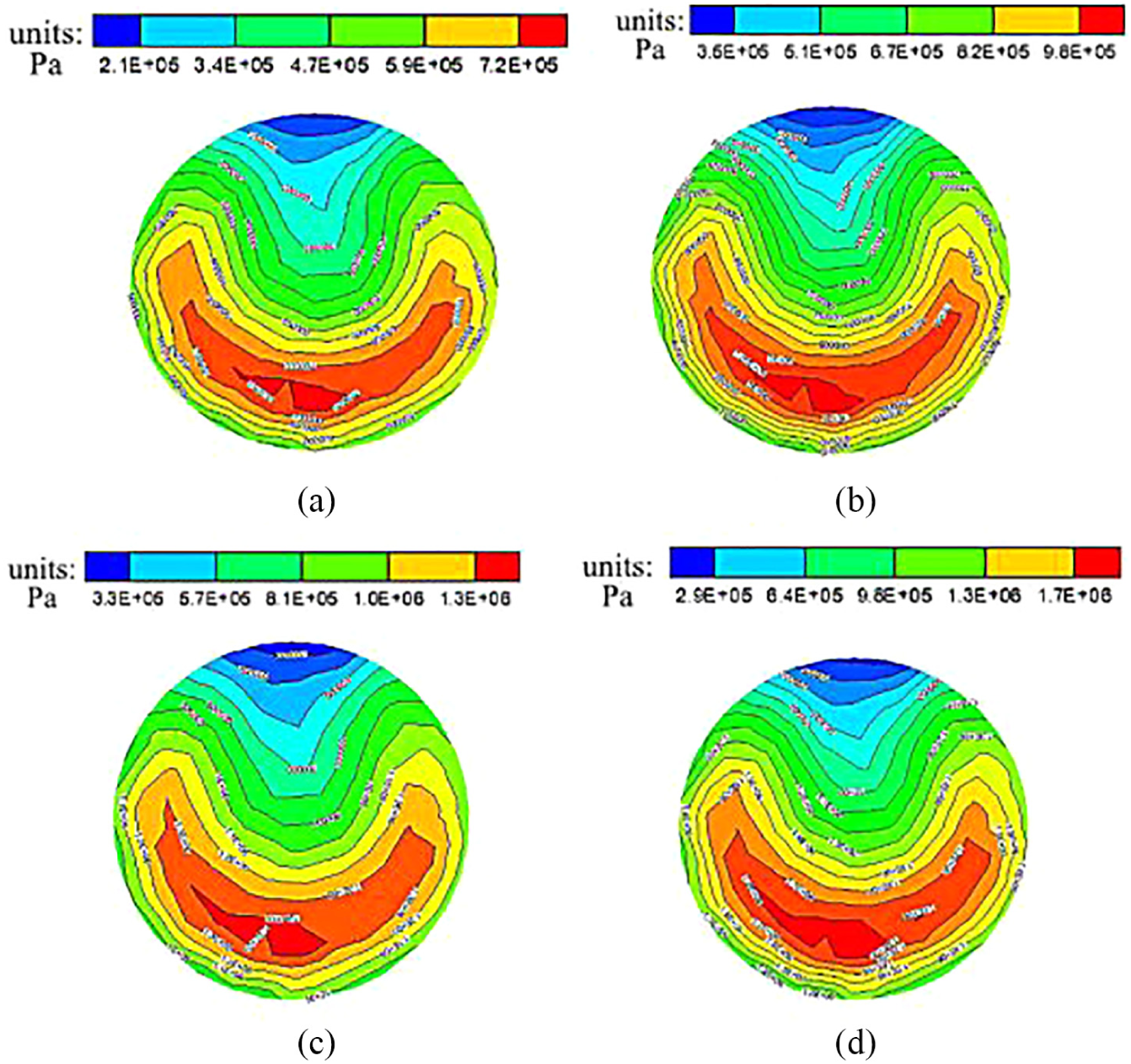
Dynamic pressure at the 90° cross-section at different velocities: (a) 25 m/s, (b) 30 m/s, (c) 35 m/s, and (d) 40 m/s.
Wall shear forces and dynamic pressure at the 90° cross-section at different velocities
The dynamic pressure at different inlet velocities is analyzed in detail above. Next, the wall shear force and the dynamic pressure at the 90° cross-section at different inlet velocities are further analyzed to clarify the influence law of the abrasive flow polishing elbow.
As shown in Figures 10 and 11, the wall shear forces at different inlet velocities and the dynamic pressures at the 90° cross-section have similar distribution characteristics; as the inlet velocity increases, the wall shear force increases gradually. From Figure 11, when the inlet velocities increased from 25 to 30 m/s, the dynamic pressure of the inner and outer walls increased gradually. However, when the inlet velocities increased to 35 and 40 m/s, the dynamic pressure exhibited a decreasing trend. It can be seen that a substantial increase in the inlet velocity can improve the polishing effect of the abrasive flow. However, if there is an excessive increase in the inlet velocity of the abrasive flow, the polishing effect of the abrasive grain flow is enhanced, but the uniformity of the polishing is weakened. In the actual grinding process, appropriate adjustments can be made as required.
Analysis and discussion on the mechanism of inner surface of polishing pipe
The micro-cutting effect of the abrasive flow on the surface of the workpiece is essentially the result of the relative motion between the abrasive flow and the wall. However, during polishing of an elbow workpiece, according to the analysis of the flow structure of the abrasive flow in the elbow, the abrasive flow into the bend and outlet sections of the elbow produces swirlpool flow, since swirlpool flow is the main reason for cavitation.
Through the above numerical analysis, it is found that as the inlet velocity increases, the wall shear force and dynamic pressure also increase, but in the bend section, the dynamic pressure first increases and then decreases. And it is also found that the greater the speed, the pressure difference. The pressure difference in the bend section and outlet section between the inner wall and the outer wall is also increasing, which indicates that the polishing uniformity is lowered. Based on the above considerations, the abrasive flow polishing test was performed on the elbow at a speed of 30 m/s, and the surface morphology after the abrasive flow polishing was observed.
To confirm the effectiveness of abrasive flow polishing technology in improving the surface quality of elbow parts, and to analyze the formation mechanism of the inner surface of the elbow during the polishing process, the experiment of abrasive flow polishing 90° elbow was conducted. The 90° elbow used in the test was the same size as that in the numerical simulation. By inspecting the surface quality of the parts and comparing the surface morphologies of the abrasive flow before and after polishing, the feasibility and effectiveness of the abrasive flow polishing of the pipe were determined.
Figure 12 shows the surface morphologies of the different parts of the pipe after the abrasive flow polishing test. The inner surface of the elbow has uneven sections and the surface quality is poor. After the abrasive grain polishing, the uneven surface of the elbow was significantly reduced, and there are irregular scratches in part of the inlet section after polishing. In addition to the scratches, there are more cavitation points in the bend and outlet sections.
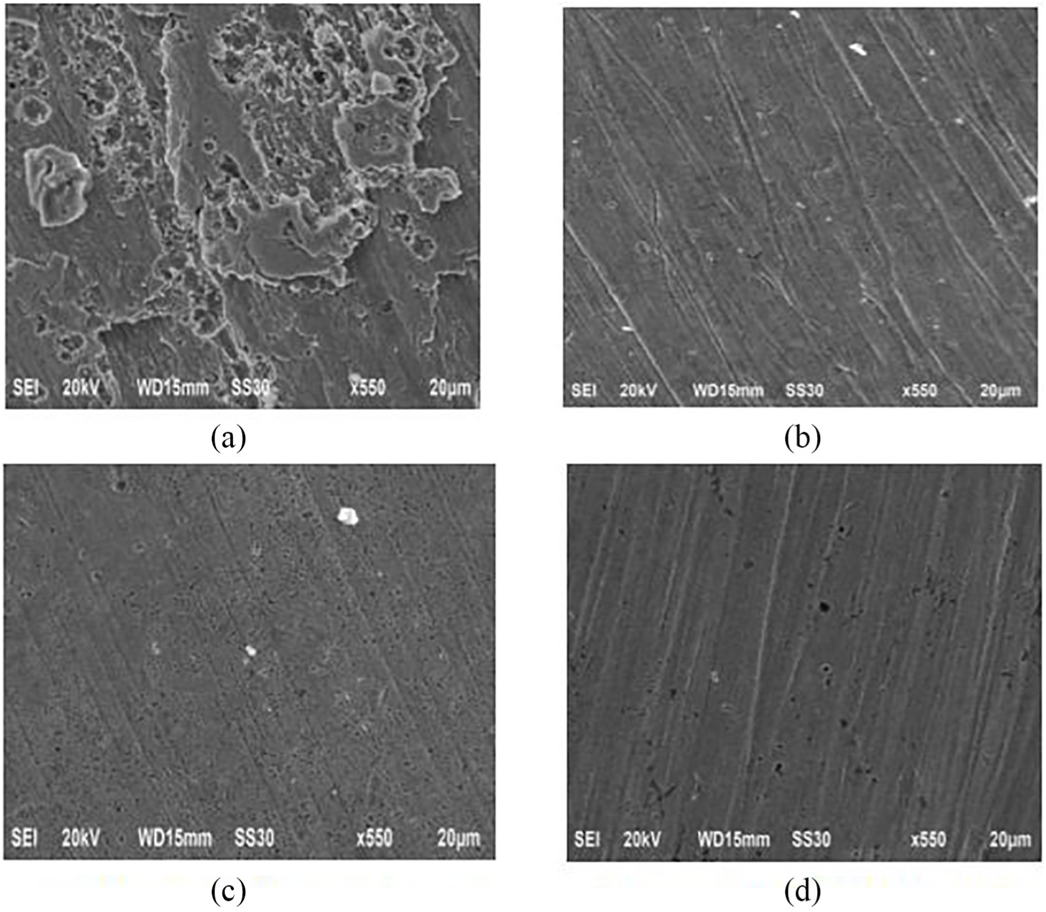
The surface morphologies of the different parts of the pipe after the abrasive flow polishing test: (a) surface morphology before polishing, (b) surface morphology of inlet section, (c) surface morphology of bending section, and (d) surface morphology of outlet section.
There are two formation mechanisms of the surface in the elbows during the polishing process, depending on whether there is swirlpool formation. In the inlet section, the surface morphology of the workpiece is mainly due to abrasive erosion. The bend and outlet sections mainly undergo cavitation wear. In the process of cavitation, erosion occurs as bubbles burst after the formation of shock waves on the abrasive particles. This increases the impact rate of abrasives and increases the impact of abrasives on the workpiece wall. Cavitation results in a spotted surface appearance of the workpiece material, and the impact of abrasive flow increases these spots. During repeated cavitation and abrasive impact, the role of pitting increases, which changes the surface roughness of the workpiece material.
Conclusion
Through the analysis of dynamic pressure, the following are concluded:
The pressure in the inlet section decreases stepwise, and the core region of the bend section moves gradually from the central area of the elbow to the outer area; the cross-sections at 60° and 90° exhibit a significant low-pressure zone on the inner wall; and the dynamic pressure in the outlet section of the outer wall is greater than that in the inner wall.
Through the analysis of the flow state of the abrasive flow at different cross-sections, owing to the abrasive flow incompressible characteristics, the constraints of the pipe structure, and the bend section of the impact under centrifugal force, a whirlpool flow phenomenon is initiated in the bend section of the abrasive flow, where the whirlpool and the movement of the mainstream caused the abrasive flow to spiral.
Through the analysis of the characteristics of shear distribution on the wall, in the inlet section with the same cross-section as the area at the elbow of the wall, the shear force distribution is more uniform. Under the influence of the change in the structure of the elbow, the shear force of the outer wall in the 0°–30° zone of the bend section is lower than that of the inner wall; in the 30°–90° region of the bend section and the outlet section, the outer wall shear force is higher than the inner wall shear force.
The solid–liquid two-phase abrasive flow of the elbow is determined by the formation of the vortex; the non-vortex area is mainly part of the elbow inlet section. The surface morphology of the workpiece is mainly due to abrasive erosion. The removal of the material is caused by reciprocating collision erosion of the abrasive grains. The vortex area is mainly the bend section and the outlet section of the elbow, which undergoes mainly cavitation wear, where the collision caused by the collapse of bubbles near the wall of the workpiece and the interaction of the abrasive grains causes fatigue damage to the surface material of the workpiece. This results in the removal of the workpiece wall material.
Footnotes
Declaration of conflicting interests
The author(s) declared no potential conflicts of interest with respect to the research, authorship, and/or publication of this article.
Funding
The author(s) disclosed receipt of the following financial support for the research, authorship, and/or publication of this article: The authors would like to thank the National Natural Science Foundation of China (Grant No. NSFC 51206011), Jilin Province Science and Technology Development Program of Jilin Province (Grant Nos. 0160101270JC and 201702040 64GX), and Project of Education Department of Jilin province (Grant No. 2016386).
Informed consent
All presentations of case reports have consent for publication.