
Abstract
Design for manufacture and assembly is a critical step in the product design life cycle. In this study, design for manufacture and assembly theory was applied to the design of a polycentric paediatric prosthetic knee to resolve assembly and manufacture issues prior to product prototyping. Assembly time and efficiency prior and subsequent to design for assembly analysis was calculated. By combining redundant parts and improving the ease of alignment, orientation, and insertion of various parts through modification of part features, a 10.1% increase in assembly efficiency was achieved. Design for manufacture analysis was then performed for die casting of the component. Undercut features were removed and replaced with the use of standard components, reducing the assembly time of the component by reducing the complexity of parts. Proposed design changes were verified using finite element analysis to simulate the loading conditions of a polycentric prosthetic knee as per the ISO10328:2006 standard for methods of testing prostheses. An overall improvement of 13.6% in assembly efficiency was achieved after the design for manufacture and assembly analysis. The improvement is due to the decrease in assembly insertion time and eliminating small parts and parts in areas that were difficult to access. The reduction in assembly time will directly reduce the labour cost for assembly of the manufactured product. This case study illustrates how design for manufacture and assembly theory can be applied to the design of biomedical equipment to reduce the need for prototype re-work and the consequent costs.
Keywords
Introduction
Efficient product development has become increasingly important, particularly in cases where reduced product development costs are desirable. Several studies have produced frameworks for more efficient means of product development.
Maropoulos et al. 1 highlighted the need for designers to establish and control the production consequences of design decisions in the early design phase and used aggregate process models to predict and prevent the progression of decisions that would lead to manufacturing difficulties and consequent costs.
Francis et al. 2 explored a Design for Verification framework with the aim of reducing costs in the competitive aerospace manufacturing industry which resulted in optimised assembly processes and more cost-effective tool and jig design. Faraz et al. 3 developed a design and manufacturing framework for discrete sheet metal parts which links the design and manufacturing cycles – a crucial step in reducing downstream manufacturing costs.
Several studies such as Corrado and Polini 4 and Zhao et al. 5 investigate improving assembly efficiency and consequent costs through tolerance analysis and assembly sequence planning, respectively.
In South Africa and other developing countries, it is crucial that products are developed locally to reduce import costs and improve accessibility, particularly for applications such as prosthetic devices where consumers are in need of a functional product but cannot afford the cost of imported components.
Design for manufacture and assembly (DFMA) is a design philosophy of the product development life cycle, aimed at making the designer aware of possible manufacturing and assembly issues that may occur during the process. This process is integral to reducing product development costs by reducing the likelihood of manufacturing and assembly difficulties before the prototyping phase and thus the need for and associated costs of design re-works. Several case studies have applied DFMA principles to product design to improve the design efficiency and reduce prototyping and assembly costs.6–12
The results of DFMA can be split into those related to design for manufacture (DFM) and design for assembly (DFA). DFM is concerned with making parts or components ‘ready-for-manufacture’ by the chosen manufacturing method, while DFA is concerned with assembly operations of those parts and the time taken to completely assemble the component.
DFA results in a simplified assembly with a reduced part count, which correspondingly reduces the required assembly time and assembly cost. The resulting design concept is then said to be in its ‘best’ form, and ready to proceed with DFM.
DFM produces a detailed design by incorporating consultation of the manufacturing engineer; thus ensuring the risk of manufacturing difficulty and iterative prototyping, and the added costs thereof, are minimised. The DFMA process overall produces a component ready for prototype production and decreases the time from prototyping to deployment.
DFMA of a paediatric prosthetic knee
This case study focusses on applying DFMA methodology to a polycentric paediatric prosthetic knee, as shown in Figure 1, which was designed for local manufacture to reduce import costs typically seen in this component. The polycentric knee is an external passive prosthetic knee capable of producing a moving centre of gravity for increased stability during walking. The large number of parts and assembly operations of the knee makes it a prime candidate for DFMA prior to prototyping to reduce costs.
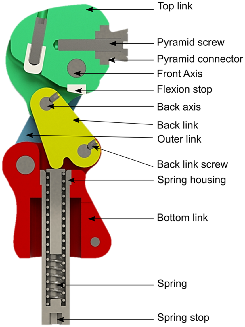
Paediatric prosthetic knee assembly.
Methodology
DFA
The methodology developed by Boothroyd et al. 13 was implemented to analyse the assembly time and efficiency of the paediatric prosthetic knee. Assembly efficiency of the part is based on manual handling time, manual insertion time, and the theoretical minimum number of parts.
The assembly efficiency can be calculated by the following equation
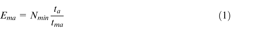
where Ema is the assembly efficiency; Nmin is the theoretical minimum number of parts; ta is the basic assembly time for one part that is an average value of 3 s for a part that presents no handling, insertion, or fastening difficulties; and tma is the total assembly time for all parts (the sum of handling time and insertion time for all parts and processes). Reducing the number of parts of the proposed design and analysing the most time-consuming parts in terms of handling, insertion, and fastening allows for improved manual assembly efficiency.
The handling and insertion times are calculated based on the part characteristics of each part in the assembly. The handling time for each part is decided using a two-digit code, the first of which assesses the part’s handling manner and symmetry. Handling manner may be classified as handling with one hand, one hand using grasping aids, parts that nest or tangle in bulk (springs, etc.), or two hands needed for handling and manipulation.
The alpha symmetry (α-symmetry) of a part is the number of degrees through which the part must be rotated about the axis perpendicular to its insertion axis, and the beta symmetry (β-symmetry) is the number of degrees through which it must be rotated about its insertion axis. The second digit assesses other characteristics of the part, based on the first digit. These factors are part size, thickness, weight, nesting and tangling characteristics, fragility, flexibility, slipperiness, and stickiness. Higher digit codes indicate a part which presents more handling difficulties, and correspondingly higher handling times.
The insertion time is calculated in the same manner, with the first insertion digit depending on whether the part is immediately secured or not, or if the assembly operation is a separate process (adhesive insertion, welding, screw tightening, etc.). Securing parts that are not immediately secured must be accounted for as a separate process. If the part has obstructed access or restricted vision hindering its insertion, the first insertion digit is higher, corresponding to a higher insertion time. The second insertion digit depends on the first digit, as well as the type of holding down required, any resistance to insertion of the part, ease of aligning the part, and the type of process (bending, riveting, welding, liquid insertion, etc.).
The total assembly time for each part is thus the sum of the handling and insertion times for that part. The total assembly time for the component is the sum of the assembly times for each part. The paediatric knee consists of 32 parts.
The theoretical minimum number of parts distinguishes the parts which could theoretically be eliminated by combining them with the receiving part. This is achieved by assessing three criteria for each part, namely:
Does the part move relative to the other parts already assembled during normal operation?
Must the part be made of a different material than, or be isolated from, all other parts already assembled?
Must the part be separate from all assembled parts to allow the assembly of parts meeting the first two criteria?
A part for which the answers to all of the above criteria is ‘no’ is an invalid part, suggesting it can be combined with the receiving part.
A Python script was created to calculate the handling and insertion times for each part and the theoretical minimum number of parts, using functions created to read part data from .csv files (comma separated value files) containing information pertaining to the factors discussed (size, thickness, resistance to insertion, etc.). The assembly efficiency was then calculated.
Results
Original part analysis
The critical findings with respect to handling and insertion of parts are discussed below.
Handling and manipulation
Most parts can be manipulated with one hand during assembly. However, the back link screws, which fix the back axes to the back link, are 3 mm in diameter and require tweezers for handling. Furthermore, the extension assist spring, which allows the knee to return to the extended position after flexion during walking, is subject to nesting and tangling when in bulk.
The majority of the parts have an alpha symmetry of 360°, meaning they must be rotated four times about an axis perpendicular to the insertion axis for the correct orientation. The exceptions are the front and back axes, the shim rings, and the spring, which have an alpha symmetry of 180°.
The parts of the assembly are largely cylindrical and have beneficial beta symmetries of 0°. This excludes the back axes and the flexion stop, which have beta symmetries of 360° due to the need for specific alignment. For the back axes, the pilot holes must be aligned with the threaded holes in the back link to enable insertion of the back link screws, as shown in Figure 2. For the flexion stop, the protruding edge must be aligned with the top of the top link to enable the flexion stop to be flush against the back link when the knee is in maximum flexion, as shown in Figure 3.
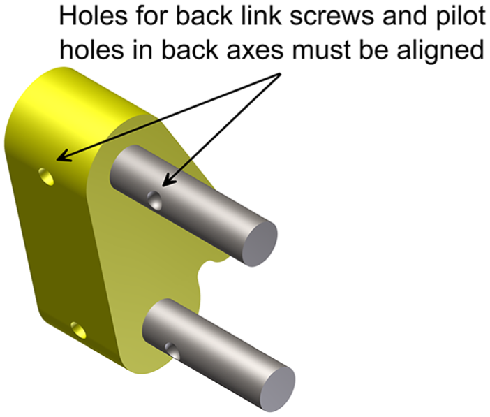
Required alignment for insertion of the back axes.
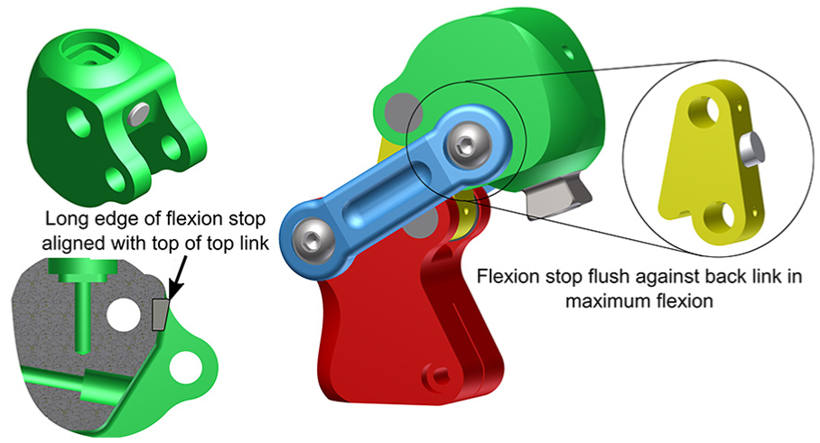
Required alignment for insertion of the flexion stop.
All parts present no further handling difficulties making the handling digits dependent on the alpha symmetry, beta symmetry, size, and thickness.
Insertion and separate processes
The assembly, shown in Figure 1, consists of 38 insertion operations. The critical areas affecting insertion time are discussed below.
Most of the parts are not secured immediately, but are secured by subsequent insertion of the parts that follow, or by fasteners. For example, the outer links, shim rings, and bearings are secured by screws. The insertion areas of the bearings, shim rings, back link, and extension stop are small, resulting in obstructed access, while the back link screws have restricted vision access since the pilot holes in the back axes cannot be seen, and obstructed access due to the difficulty in aligning these pilot holes with those in the back axes and back link.
Parts that require holding down once inserted include the outer links, shim rings, the top link, and the back link.
Alignment of parts and torsional resistance during insertion presents the most difficulty in the assembly process. Alignment of the flexion stop must be precise to operate correctly during maximum flexion, as discussed in section ‘Handling and manipulation’; however, no locating feature is provided to aid this alignment. Similarly, when inserting the back axes into the back link, the pilot holes must be aligned with those in the back link to enable insertion of the back link screws; however, visibility is limited and no locating feature is provided.
The insertion operation of the axes into the various holes presents resistance to insertion due to the lack of appropriate chamfers. For parts of equal dimension (hole and hub) or zero dimensional clearance, those with chamfers on both the hole and hub have the lowest insertion times. 13
A single separate process is included in the assembly that is the insertion of the adhesive required to bond the flexion stop to the top link. This is classified as a non-mechanical fastening process that is chemical and has a large associated insertion time.
Analysis results
Part data files were passed to the analysis programme created. Resultant handling and insertion times, the resultant theoretical minimum number of parts, the corresponding theoretical assembly time, and the assembly efficiency are listed in Table 1.
Design for assembly analysis results.
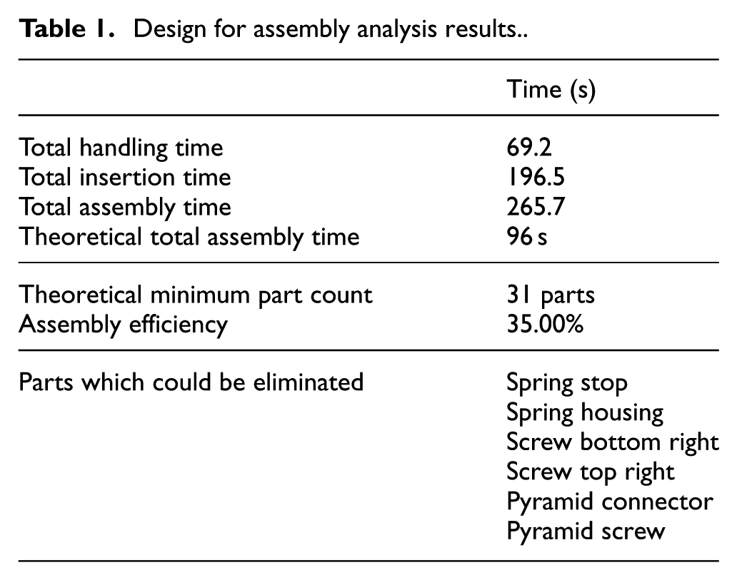
The theoretical minimum number of parts is 31, with the parts suggested for elimination or combination listed in Table 1. The assembly efficiency is significantly low at 35.0%. To propose design changes most capable of producing a more efficient assembly, a comparison of the handling and insertion times of the various parts are displayed in Figures 4 and 5, respectively. The handling times are per individual part, for example, a handling time of 1.8 s for the bearing indicates the time to handle one bearing.
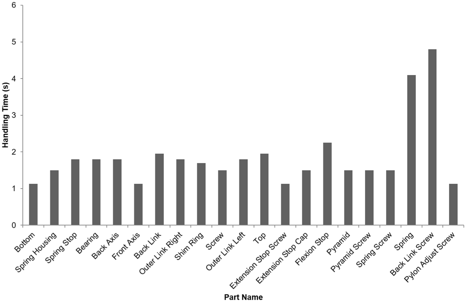
Bar graph displaying the handling time per part.
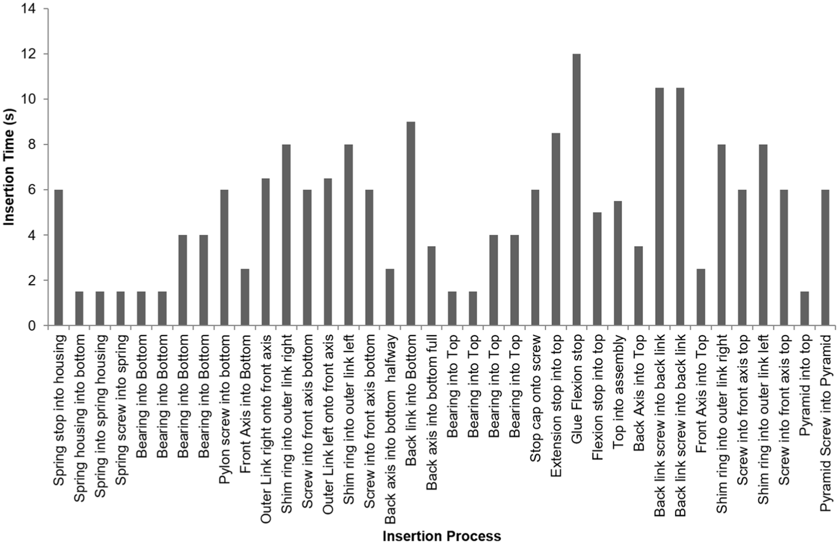
Bar graph displaying the insertion time per process.
When examining the part assembly times, the areas of concern are the back link screws, the back axes, the flexion stop, and the spring. The back link screws account for almost 14% of the handling time and over 10% of the insertion time. This is largely due to their small size and the difficulty in inserting them through both the back link and back axes while still maintaining alignment of the pilot holes.
The pilot holes in the back axes cannot be aligned with those of the back link since the flat end of the axis sits flush against the outer surface of the bottom link once inserted. The axes cannot be rotated into the correct alignment, obstructing the access of the back link screws. The flexion stop accounts for over 3% of the handling time and over 8% of the insertion time due to its alignment difficulty and the time required for the separate adhesive bonding process.
Difficulty with the spring assembly is a result of the nesting and tangling nature of springs when stored in bulk, as would be the case in an assembly line, resulting in a handling time that accounts for over 12% of the total handling time. Several design changes are proposed in section ‘Proposed design changes’ to address these identified difficulties.
Proposed design changes
Reducing part count
The parts able to be eliminated or combined by the theoretical minimum parts analysis are addressed as follows:
Spring stop – The spring stop is responsible for locating the spring in the spring housing. The stop could be combined with the spring housing such that the housing could be closed at the spring stop end. However, it is necessary to maintain them as separate parts to allow adjustment of the extension spring stiffness to patient needs by travelling the spring stop along the inside of the housing to stiffen the spring. While motion does not occur during the flexion and extension modes of operation, it is needed for correct operation of the extension assisting spring.
Spring housing – The spring housing is eligible for combination with the bottom link. However, to allow the pylon or ‘leg’ of the prosthetic assembly to be attached to the knee, a uniform gap between the housing and the bottom link must exist. Combining the two will require a larger mould for casting the bottom link and complicates die design. The added manufacturing costs are perceived to outweigh the benefit of combining the components.
Screws – The screws on the right-hand side of the knee are eligible for combination with the front axes. This involves creating a flat head at one end of the axes, and the use of an internal thread and screw. By combining the axes and screws, two parts are eliminated.
The alpha symmetry of the front axes is, however, increased to 360°. Theoretically, axes could be inserted from the right or left side of the knee, maintaining the alpha symmetry at 180°. However, for consistency, it is assumed the axes will be inserted from the same side during each assembly. The dimensions of the front axes are also increased to account for the added flat head during handling.
Pyramid connector and screw – The pyramid connector and top link are able to be combined and cast as a single component. This eliminates two parts, the pyramid and screw, since a fastener is no longer needed between the two components. The top link dimensions are amended to include the pyramid connector.
Insertion improvements
Combining the screws and the front axes; and the pyramid connector and top link, eliminates four insertion operations. To address the difficulty in aligning the flexion stop in the correct position in the top link, a press fit pin solution was implemented. This involves placing two asymmetric pins on the region of the top link where the flexion stop was previously fastened with adhesive, as shown in Figure 6. The pins are larger in diameter than the holes created in the flexion stop, with a radial interference of δ = 0.02 mm to allow for an interference fit between the nylon flexion stop and the top link, eliminating the need for the separate adhesive bonding process. By keeping the pins asymmetric, insertion in the correct alignment is ensured since the flexion stop cannot be inserted in any other orientation. The separate process of applying adhesive to the top link is also eliminated through the press fit solution.
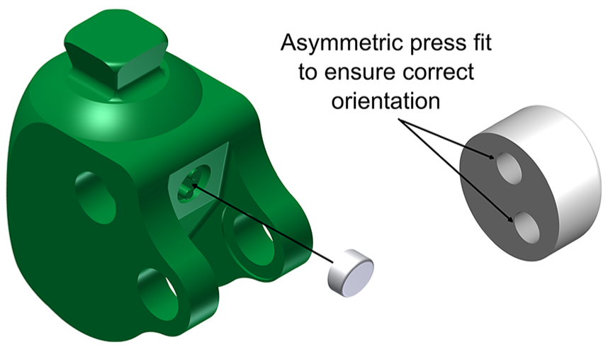
Press fit created for flexion stop insertion.
The back link screws present great difficulty in insertion due to the need for pilot holes in the back axes and back link to be aligned. Since the back axes cannot protrude past the top and bottom link without preventing flexion of the knee, twisting the axes to align pilot holes is not possible. The contact area between the back link and back axes are a high stress area, discounting use of locating features such as keys.
To allow the axis to be correctly aligned, an M4 allen key hole was created on both sides of the back axes to allow the axis to be twisted into place once inserted, aiding the alignment. This removes the difficulty in aligning the back axes and the back link screws as well as the obstructed access of the back link screws.
Chamfers were added to all axes and holes to aid resistance to insertion. Boothroyd et al. 13 found that a chamfer on the shaft and hole with a width of w = 0.1D, where D is the hole diameter, is most effective in reducing insertion time. The addition removes resistance to insertion of the axes and related insertion operations.
Theoretical time savings
The characteristics and minimum theoretical parts files were amended as discussed above and the created programme was re-run with the new characteristics. The results of the analysis are listed in Table 2.
Design for assembly analysis results after design changes.
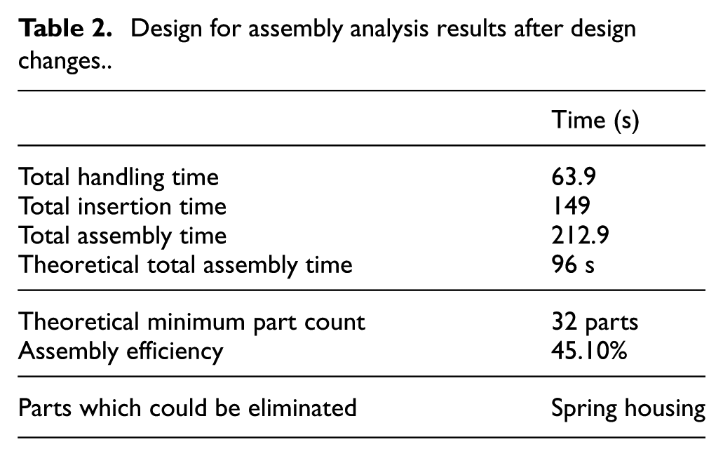
The design changes resulted in a 10.1% increase in assembly efficiency. The handling time decreased by 7.6% and the insertion time by 24.7%.
The largest time saving was due to the reduction in part count. By combining the pyramid connector and the top link, 3 s of handling time and 7.5 s of insertion time was eliminated. Combining two screws and the front axis reduced insertion time by 12 s due to the large time required for screw tightening operations. However, handling time for the front axes increased by 0.4 s due to the increased alpha symmetry, an acceptable trade-off for the resulting time reduction. The press fit connection for the flexion stop reduced the insertion time by 88%.
The main issues affecting the assembly time subsequent to the DFA analysis are the various threaded components in the assembly such as the pylon adjustment screw, the extension stop screw, and the spring stop screw. However, these are required to maintain the adaptability of the component to allow for patient-specific changes to be made. This is essential for the knee to be marketed as a long lasting component, allowing cheaper components, such as the pylon, to be replaced and used with the same knee over a longer period of time. Parts such as shim rings are not integral to the assembly; however, failure of the assembly links (the top link, bottom link, outer links, and back links) will result in a far greater replacement cost than failure of the shim rings, bearings, and axes, justifying their inclusion.
By combining redundant parts and ensuring each part can be easily aligned, oriented, and inserted during the assembly, the theoretical assembly efficiency was improved from 35.0% to 45.1%. The DFA analysis is thus successful in reducing the operator time required to assemble the component, and thus the overall assembly cost.
DFM
DFM follows the DFA analysis, with the aim of ensuring the part can be produced using the chosen manufacturing method. In the case of the paediatric knee, the material selection was optimised using the ELimination Et Choix Traduisant la REalité (ELECTRE) III multiple attribute decision making (MADM) method as discussed in Mangera et al. 14 Applicable manufacturing processes were then chosen based on those available at the research institute to enable local manufacture and reduce import costs. Semi-solid metal high pressure die casting (SSM HPDC) and investment casting are suggested for high and low volume production, respectively, and the components must be adjusted to suit the processes.
Castability is a measure of how easy it is to cast a quality part. This can be related to the material properties (pouring temperature, fluidity, shrinkage, slag formation tendencies, etc.), or to part design. 15 In terms of the DFM of the paediatric knee, the aim is to improve castability of the parts as it relates to part design.
DFM die casting principles
Boothroyd et al. 13 have outlined several design principles to be considered when designing parts for die casting:
Die castings should be thin-walled structures to ensure smooth metal flow during filling and minimise distortion and shrinkage during cooling.
Features projecting from the main wall of a casting should not add to the bulk of the wall at the connection point.
Features projecting from the side walls should not lie behind one another when viewed in the direction of die opening to prevent the use of side-pulls in the die.
Internal wall depressions or undercuts should be avoided since moving internal core mechanisms are virtually impossible to achieve with die casting.
Botef 15 states that undercuts and internal features are undesirable. The undercut does not allow the part to be ejected from the die and may cause the part to break at the undercut during ejection. Undercut features must thus be machined subsequent to casting. Botef 15 discusses part features that reduce castability:
Long thin sections are difficult to fill.
Sudden changes in wall thickness induce turbulence during filling, leading to porosity and poor part quality.
Annulars in the path flow create cold-shuts and mis-runs.
Non-planar parting lines increase tool complexity.
From the above principles, it can be deduced that the casting die greatly influences the DFM process. During investment casting, the mould is created from a wax pattern and destroyed, allowing complex geometries without the need for features such as drafts and consideration for undercuts needed in high-pressure die casting. The remaining DFM analysis will thus focus on the adjustments required for SSM HPDC casting.
High-pressure die casting dies consist of two sections, a stationary half called the cover die half and a moveable half called the ejector die half; the halves meet at the parting line. Unlike plastic injection moulding processes, where the liquid material has high viscosity, casting alloys have the tendency to flow between contacting surfaces of the die, a phenomenon known as ‘flashing’ that causes the mechanism to jam. In addition, high core retration forces due to shrinkage make internal core features, such as internal threads and undercuts, difficult to achieve.
Part analysis for die casting
In line with the above principles and on consultation with manufacturing engineers, several adjustments were required to ensure feasible die casting the links of the paediatric knee. The parts to be cast are the top link, the bottom link, the two outer links, and the back link. The greatest concern when considering SSM HPDC for the links is the large amount of internal features and undercuts. Adjustments needed for each part are discussed.
Bottom link
The bottom link has undercuts at the back to accommodate thickness of the bearing, as shown in Figure 7. The use of a smaller bearing and axis would remedy the need for the undercut; however, a smaller axis is not feasible due to the low factors of safety using the current stainless steel material. Machining of the undercut post-casting is difficult since the space available for the tool to enter is only 16 mm.
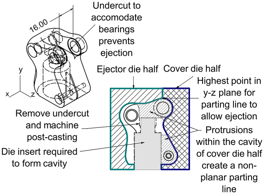
Undercuts to be addressed in the bottom link.
To remove the need for the bearing undercuts, the manner in which the knee rotates can be reversed and the back axes replaced with shoulder screws. Presently, the back link is fixed to the back axes, which rotate within the bearings in the top and bottom links. By threading one of the receiving holes on the top and bottom links and using a high-strength grade 12.9 M6 shoulder screw as back axes, the back axes become fixed to the top and bottom links and rotate within the bearings inserted into the back link. Using an M6 shoulder screw reduces the diameter and thus the thickness of the flat surface of the bearings, eliminating the need for the undercut to fit the 8 mm bearings. The material strength of the reduced diameter axes must be verified. The solution is displayed in Figure 8.
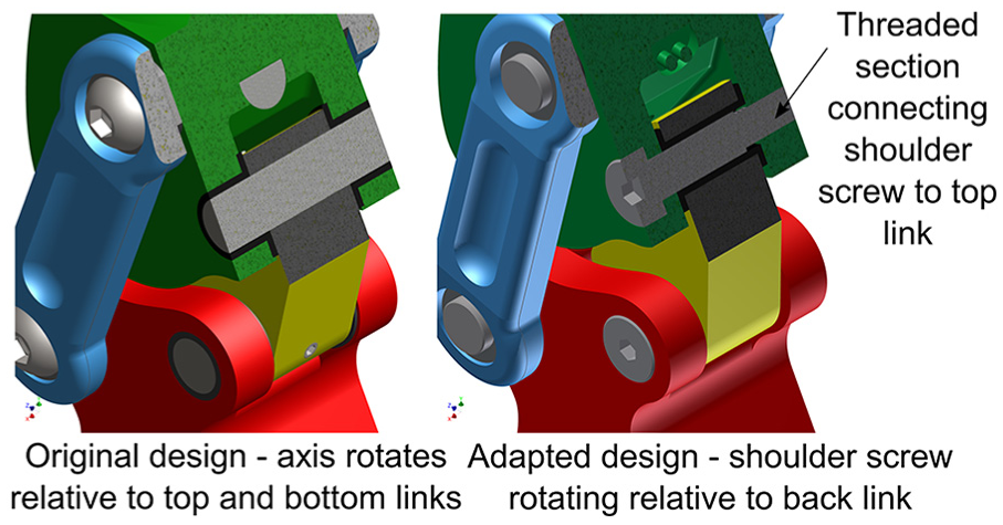
Shoulder screw solution to eliminate bearing undercuts.
Functionality of the knee is maintained through the solution. This also eliminated the need for the back link screws that presented assembly difficulties. The solution also eliminated the need for similar undercuts in the top link.
When considering the separation of the die halves, a planar parting line is preferable. The parting of the die halves must allow the part to be ejected from the mould once cast. For example, an x–z plane parting line for the bottom link prevents the part from being extracted from the die halves due to the large number of undercuts and curved features when the part is viewed in the y–z plane. A y–z plane parting line does not allow for the casting of the 16 mm gap in the bottom link without preventing the part from being extracted. The best solution, an x–y plane parting line was chosen, as shown in Figure 7. The highest point in the y–z plane was used as the parting line to allow the part to be extracted. However, protrusions required to cast the 16 mm gap and the gap that allows the tightening of the pylon adjustment screw for attachment of the pylon created a non-planar parting line. Furthermore, an insert is required to create the hollow section for the spring assembly and the pylon. This is a favourable feature for SSM casting, as it reduces the wall thickness during casting. The shoulder for the spring housing can be removed and machined post-casting. The holes required for the axes can be achieved by machining subsequent to the casting process, or with the use of die inserts.
Top link
The shoulder screw solution implemented for the bottom link was repeated to eliminate the bearing undercuts on the top link as discussed. The most suitable parting line is shown in Figure 9.
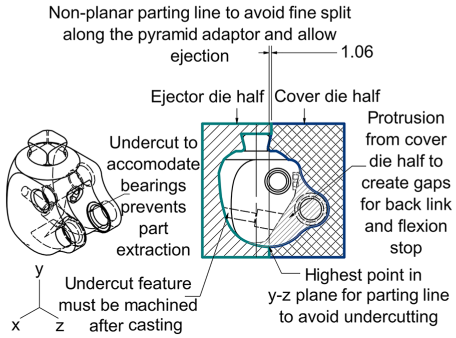
Undercuts to be addressed in the top link.
The parting line was again at the highest point in the y–z plane to allow part extraction. However, for a single plane parting line, the pyramid connector would be sliced by 1.06 mm between the two die halves and be compromised during casting. It was recommended that the highest point on the lower surface be moved backwards to align with the top-most edge of the adaptor, as this would not compromise the knee’s functionality.
The gap creating the hollow section of the top link, in which the front face of the back link lies in the assembly, was created by means of a protrusion in the cover die half. The hole that houses the adjustable stance phase flexion stop would prevent part extraction due to the angle of inclination and can be machined post-casting. Holes required for the axes can be achieved by machining subsequent to the casting process, or with the use of die inserts.
Outer links
The outer links require no adjustments for die casting due to their simple shape, which would not be difficult to machine or die cast. The die structure is displayed in Figure 10.
Suggested die structure for outer links.
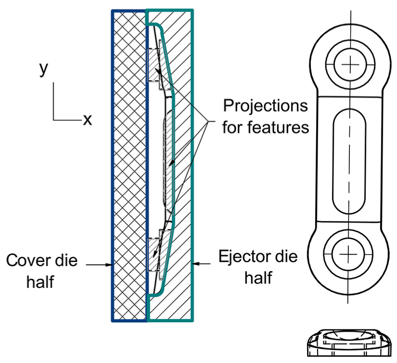
Back link
The back link required a y–z plane parting line to avoid the undercut feature, if an x–y parting plane is used as shown in Figure 11. Three projections are required on the ejector die half to produce the required holes and features and present no undercutting difficulties.
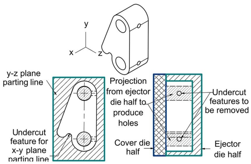
Undercuts to be addressed in the back link.
Holes for the back link screws would create undercuts and be required to be machined post-casting; however, the shoulder screw solution discussed in section ‘Bottom link’ eliminated the back link screws and thus the need for the holes.
Draft angles
To easily remove parts from the die, drafts (or tapers) must be included on the side walls of the die cast part. The surfaces to draft are those that are perpendicular to the parting line of the die and any internal cores with walls perpendicular to the core-part parting line. As the material cools within the die, slight shrinkage occurs. By tapering the walls of the die, removal becomes easier by reducing the tendency of the part to adhere to the die, reducing the cycle time, and improving the surface quality of the part. An exaggerated 10° draft is displayed for the outer link in Figure 12. Drafts were created at 1.5°.
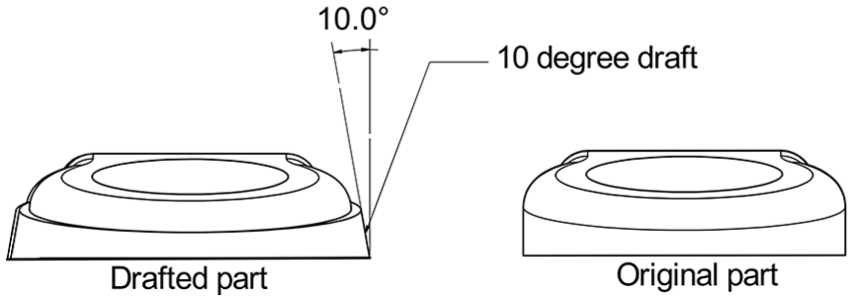
An exaggerated example of a draft created for the outer link.
Validation of changes
To validate the changes suggested by the DFMA analysis, the revised geometry was re-tested using finite element analysis (FEA) for the worst case scenario, load case II of the ISO10328:2006 standard. 16
The front axes were amended to aluminium 7175 and reduced in diameter to 6 mm to accommodate insertion as discussed in section ‘Reducing part count’. To avoid fine meshing of the washers due to their small thickness, these were combined with the axes and screws. The back axes or shoulder screws were specified as class 12.9 steel as per BSI 1999 17 with a yield strength of 1100 MPa. The Young’s modulus and Poisson’s ratio were specified as 210 GPa and 0.3, respectively. 18
The top link and pyramid connector were merged as a single body and the pyramid screw and its holes removed. The press fit connection of the flexion stop was not modelled, as testing occurs in the extended position.
The changes to be verified were as follows:
The combined top link and pyramid connector using the SSM material.
The back link and shoulder screw assembly with reduced diameter back axes.
The reduced diameter front axes and bearings.
Factors of safety and deformation for all parts were calculated as a solution output. Maximum deformation occurred at the top left side of the knee, closest to the load application point. The minimum factor of safety of 0.2 occurred on top front axes, closest to the applied load, indicating failure. Similarly failure occurred at the bottom front axis with a factor of safety of 0.2. The original minimum factors of safety for the front axes prior to DFMA were 1.20 and 1.14 for the top and bottom axes, respectively. Reduced diameter bearings on the left side of the knee also failed with factors of safety just below 1, which originally had a minimum factor of safety of 2.61. The front axes were no longer capable of withstanding required loads with the reduction in diameter.
To maintain the original diameter, washers on the right side of the knee must be removed to allow for insertion of the axes at the risk of damage to the outer link. Alternatively, a custom washer must be made. Protection of the outer link is a priority as the cast parts are expensive to replace. The use of standard parts is more cost-effective and preferable to assembly time savings achieved by eliminating the screws. The front axes were thus reverted to 8 mm diameters and fasteners re-included.
The use of aluminium 7175 for front axes with the original diameter and fasteners resulted in a factor of safety of 4.2 and 4.0 for the top and bottom axis, respectively; an improvement from the low factors of safety achieved using stainless steel axes.
Back axes or shoulder screws had minimum factors of safety of 7.3 and 9.4 for the top and bottom axis, respectively, while the back link has an improved factor of safety of 2.8 from 1.5 in the original assembly. Although the back axes were also reduced in diameter, the high strength steel shoulder screws are capable of withstanding required loads.
The minimum factor of safety of 2.1 of the combined pyramid connector and top link occurs at the pyramid, which is improved from 1.3 (stainless steel 316) with the use of the SSM alloy.
Results indicate the trade-off nature between DFMA and functional requirements, and the necessity to verify the proposed changes as a result of DFMA analysis before implementation. Incorporation of the following changes is proposed:
Combination of the pyramid connector with the top link.
Replacement of the back axes and back link screws with M6 shoulder screws.
Incorporation of chamfers on holes and hubs to improve insertion.
Incorporation of a press fit connection for alignment and attachment of the flexion stop.
Incorporation of drafts of part walls to aid die ejection.
Re-evaluated assembly time
Assembly time was re-evaluated to assess the overall improvement achieved after incorporating the changes of the DFM and design validation. Back axes dimensions were altered to match those of the standard M6 shoulder screws. 19 Alpha symmetry was increased from 180° to 360° since the axes can only be inserted from right to left. Beta symmetry was, however, reduced from 360° to 0° since alignment of the pilot holes for the back link screws was no longer necessary.
Back link screws were eliminated; however, insertion operations of the back axes must be amended to an immediately fastened screw tightening operation. Screws for the front axes were re-introduced with their respective screw tightening operations.
Handling of the bearings were split into the 6 mm bearings (back axes) and the 8 mm bearings (front axes) with their respective dimensions. Furthermore, bearings inserted into the back holes of the bottom and top link were inserted into the back link, and no longer presented obstructed access difficulties in the small 16 mm gap. Screws for the front axis must be re-introduced, and the alpha symmetry of the axes decreased from 360° to 180°.
Back link screws were removed from the minimum parts file and the front axis screws re-included. The screws were specified as required to enable assembly of a valid part. The resulting assembly time was 197.5 s (3.3 min) of which 56 s were handling time and 141.5 s were insertion time. The theoretical minimum number of parts was 32, with just the spring housing theoretically able to be eliminated, giving an assembly efficiency of 48.6%, a further 3.5% increase in efficiency as a result of DFM.
DFMA results
A comparison of the assembly times prior to the DFA analysis, post-DFA (before validation), and post-DFM analysis and validation is displayed in Figures 13.
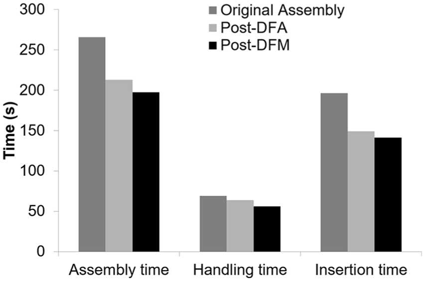
A comparison of the assembly times during the DFMA process.
A 13.6% increase in assembly efficiency was achieved through the DFMA process. Of this, the greatest improvement can be attributed to the decrease in total insertion time, as shown in Figure 13, largely due to elimination of parts. The handling time of parts was not significantly altered as dimensions and part geometries were maintained. The decrease in handling time can be attributed to the elimination of the back link screws, which required tweezers for handling and correspondingly a large amount of handling time.
The DFA analysis prior to validation and DFM represents an ideal assembly time, however, by considering manufacturing methods and ease of manufacturing, the assembly time was further reduced. The analysis shows the necessary trade-off between efficient assembly, use of standard parts and manufacturing methods, and functional requirements, and the influence of DFM on assembly time through part simplification.
The efficiency is largely based on the theoretical assembly time per part (3 s) which is likely only for very basic components. The efficiency achieved is thus satisfactory in light of the complex geometry of the current component, based on the efficiencies achieved by more complex parts reported in the literature discussed.
The final geometry should be verified through rapid prototyping methods before creating high-cost dies for SSM HPDC. The investment casting facility at the Council for Scientific and Industrial Research (CSIR) is recommended for the rapid prototyping process. The process does not require die design, as discussed above, as the mould is destroyed upon part extraction. With the advancement of local manufacturing capabilities such as additive manufacturing, it is recommended that new manufacturing methods be explored and evaluated to further improve the design and reduce manufacturing costs.
Conclusion
The DFA process directly reduced the operator cost required for part assembly by minimising the required assembly time of the component and improving assembly efficiency by 13.6%. The DFM process tailored parts for manufacturing and finishing by the selected methods and further simplified parts to maximise efficiency.
The DFMA process created part specifications ready for prototype development. Through DFMA, the cost of the prototyping process was reduced by reducing the number of iterations required to produce a functional component.
Footnotes
Declaration of conflicting interests
The author(s) declared no potential conflicts of interest with respect to the research, authorship, and/or publication of this article.
Funding
The author(s) disclosed receipt of the following financial support for the research, authorship, and/or publication of this article: This work was supported by the Department of Science and Technology (DST) of South Africa.