
Abstract
In order to study the machining mechanism and process of abrasive flow machining for the titanium alloy artificial joint surface, the abrasive flow machining experimental platform and the curved surface profiling flow channel were established for the machining. The influence of various process parameters (abrasive particle size, abrasive particle concentration, and processing time) and interaction factors on surface roughness and surface micro-topography of the workpiece was quantitatively evaluated through response surface analysis, and a surface roughness prediction model was established. The experimental results show that coverage constraint abrasive flow machining can significantly improve the surface quality of the titanium alloy artificial joint surface, thereby improving the wear resistance and service life of the artificial joint. Using abrasive flow machining with a smaller abrasive particle size and a larger concentration can obtain smaller surface roughness. Under the experimental conditions, the influence of process parameters on the surface roughness is in descending order of processing time, abrasive particle concentration, and abrasive particle size. And the interaction of processing time and abrasive particle size is more effective during processing. The research results can provide the basis for optimizing the flow channel structure for the abrasive flow machining of the titanium alloy artificial joint surface and have a certain guiding significance on the process optimization.
Keywords
Introduction
Due to their good biocompatibility and biomechanical compatibility, titanium alloys have become the preferred material for the replacement or repair of medical devices such as artificial joints, bone wound products, and artificial dental implants.1–3 Titanium alloy artificial joints are directly in contact with human body fluid environment when used as implants. The wear debris formed during the use of artificial joints will cause phagocytosis of macrophages or fibroblasts at the periphery of the joint to promote the reabsorption of bone cells, resulting in a decrease in the number of bone cells, bone resorption, and osteolysis around the artificial joint, which causes joint loosening and sinking.4–7 In order to reduce the wear of artificial joints in the human body, it is necessary to polish the surface of artificial joints to increase their wear resistance. However, currently, titanium alloy artificial joints are mainly polished by hand, so the efficiency is low and it is difficult to ensure the uniformity of the polishing effect. In addition, when the traditional grinding method is used to polish the titanium alloy artificial joint, the friction generates. Under the action of the cutting heat and pressure during the processing, the workpiece will be thermally deformed which in turn directly affects the life of the polishing tool and the surface quality of the workpiece. Besides, using cutting fluid to remove cutting heat generated during the process will cause environmental pollution, health hazards, and high cost.8,9 Aiming at the difficulties of surface polishing of titanium alloy artificial joints, a new method for abrasive flow machining of titanium alloy artificial joints was proposed which used a profiling constraint component to form the profiling flow channel for fluid processing. Abrasive flow finishing processes are mainly achieved by flowing abrasive laden viscoelastic carrier over the workpiece surfaces to be finished, 10 and the heat and debris generated during the impact of the abrasive particles could be discharged from the outlet of the flow channel.
Many researches on abrasive flow machining can be found. In Sarkar and Jain’s 11 study, a uniform mirror surface of stainless steel knee joints was achieved using abrasive flow machining, and it proved the feasibility of abrasive flow machining to achieve polishing of free-form complex surfaces. Kavithaa and Balashanmugam 12 not only described nanometric surface finishing of typical prosthetic implants and an extrusion die used in bio-medical and pharmaceutical industries but also described the polishing of the industrial components used in aerospace applications and emphasized the importance of abrasive flow machining in the field of ultra-precision machining. Dong et al. 13 established a theoretical calculation model of the normal pressure on the inner surface of a circular tube and the wall sliding velocity based on rheology theory and verified the correctness of this model by numerical simulation and actual experimental tests.
In order to discuss the influence of the process parameters of abrasive flow on the surface quality of titanium alloy artificial knee joints, a titanium alloy artificial joint workpiece and a profiling flow channel were designed for abrasive flow machining experiments. Aiming at the characteristics of multi-curvature of titanium alloy artificial joints, the influence of the process parameters of abrasive flow on the surface quality of workpiece in different curvature regions was discussed. At the same time, a prediction model of surface roughness was established. The experimental results can provide technical support for the coverage constraint abrasive flow machining of titanium alloy artificial joint surface.
Mechanism of abrasive flow machining
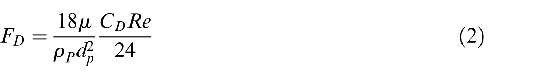
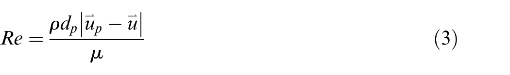
In this article, titanium alloy artificial knee joint workpiece was machined with softness abrasive flow. Softness abrasive flow is a weak viscous solid–liquid two-phase flow, 14 in which the volume fraction of the solid phase particles is generally between 0.1 and 0.3. Compared with the traditional hardness abrasive flow which has a higher volume fraction and higher viscoelastic, softness abrasive flow has better fluidity and can achieve better turbulent flow in the profiling flow channel to machine workpiece disorderly.13,15,16 In the constraint flow channel, because the abrasive particle volume fraction of softness abrasive flow is small, the collision between the abrasive particles is not considered. The movement of abrasive particles in the abrasive flow is mainly affected by a series of forces such as gravity, buoyancy, drag force, pressure gradient force, virtual mass force, Basset force, Magnus force, and Saffman force, as shown in Figure 1. The trajectory of a discrete phase particle (or droplet or bubble) can be predicted by integrating the force balance on the particle, which is written in a Lagrangian reference frame. This force balance equates the particle inertia with the forces acting on the particle and can be written as
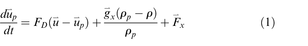
where
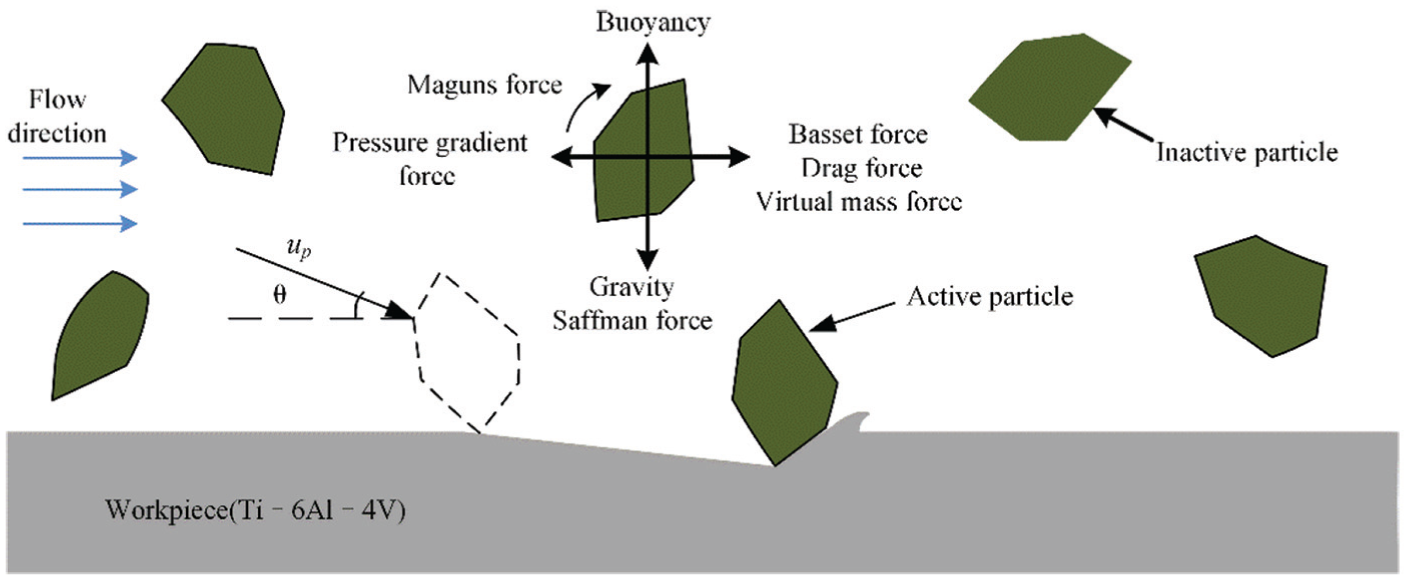
Schematic diagram of the forces on the abrasive and its cutting action.
The mechanism of abrasive flow machining is similar to erosive wear, and the effect of machining is achieved by the micro-cutting action generated by the collision between particles in the abrasive flow and the workpiece surface.17–20 If the abrasive particle is regarded as a micro-tool, the angle and speed of the micro-tool, when it collides with the workpiece surface under the action of the flow field, are randomly distributed. 21 The horizontal component of the micro-tool force mainly causes the plowing damage to the target, and the vertical component mainly causes the impact damage. Those two damage mechanisms will convert each other as the impact angle changes. Abrasive particles in the abrasive flow can be divided into two states. One is an “active particle” that comes into contact with the workpiece surface and produces the cutting action, and the other is an “inactive particle” that does not come into contact with the workpiece surface or comes in contact with the workpiece surface but does not generate the cutting action.22,23
According to the erosion model of Oka and colleagues,24,25 which was obtained based on a large number of erosion tests and found to be applicable under any impact conditions for any type of material, an abrasive particle with velocity


where
Equations (4)–(7) show that when the workpiece material and the abrasive particle are certain, the effect of removing the material mainly depends on the impact speed and the impact angle of the abrasive particle when it impacts the surface of the workpiece. In the abrasive flow machining experiment, a large number of abrasive particles continuously impact the surface of the workpiece in a random state to form the removal effect in order to achieve the polishing effect.
Design of abrasive flow machining experiment
The experiment mainly studies the influence of some key process parameters such as abrasive particle size, abrasive particle concentration, and processing time on the abrasive flow machining of titanium alloy artificial joint surface. The machining experimental platform is shown in Figure 2. The Ti-6Al-4V titanium alloy artificial joint workpiece is fixed on the channel base and it forms a profiling flow channel with the constraint component. The inlet of the abrasive flow is connected with the outlet of the slurry pump. The pump suction hole is connected with the agitation tank, and the outlet of abrasive flow passage leads to the agitation tank at the same time. The titanium alloy artificial joint workpiece is polished using self-made abrasive flow. The changes in the surface roughness Ra and the surface topography of the workpiece were observed and recorded to study the influence of various process parameters on the surface quality to verify the reliability and feasibility of abrasive flow machining.
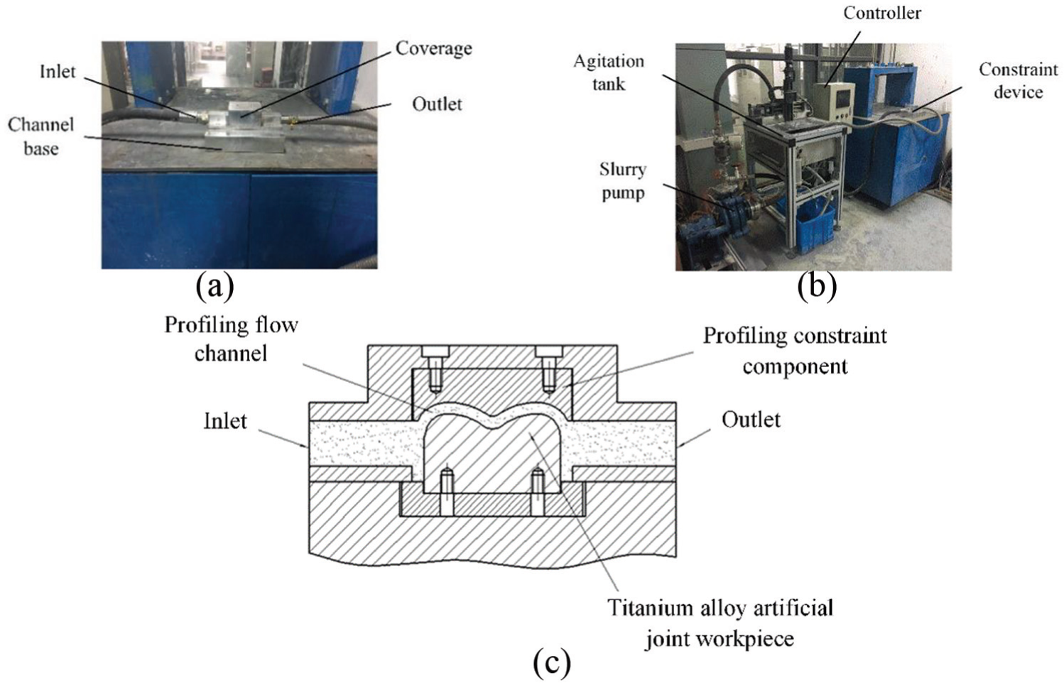
Abrasive flow machining system and machining principle: (a) constraint device, (b) machining system, and (c) machining principle.
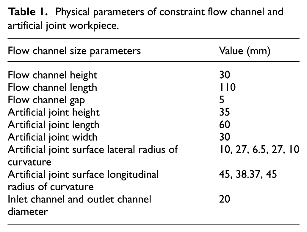
The constraint flow channel is a profiling flow channel with a symmetrical structure, as shown in Figure 3. The flow channel is locally profiled according to the shape of the workpiece surface which is composed of workpiece surface, profiling constraint component surface, inlet channel, and outlet channel. The specific parameters are shown in Table 1.
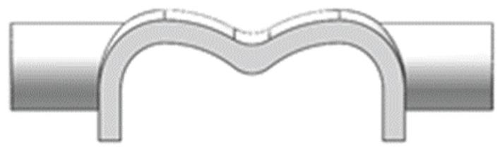
Schematic diagram of constraint flow channel.
Physical parameters of constraint flow channel and artificial joint workpiece.
In order to study the effect of abrasive flow machining on the surface quality of workpieces on different curved surfaces, the surface of the workpiece is divided into I, II, III, IV, and V regions. The five regions correspond to five curvatures. Among them, I and V are the lateral epicondyle regions of the knee joint, II and IV are the lateral condyle regions of the knee joint, and III is the intercondylar notch region of the knee joint, as shown in Figure 4. The surface of the workpiece was pre-polished using sandpaper. After polishing, the original surface roughness Ra of the five regions was about 230.0 nm (measure nine points per area for averaging).
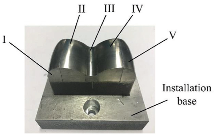
Titanium alloy artificial joint workpiece.
The experiment of coverage constraint abrasive flow machining of titanium alloy artificial joint surface is conducted under the following conditions: abrasive grain size of 8–18 μm, abrasive grain concentration of 0.1–0.2, processing time of 0–5 h, inlet flow rate maintained at 11 m3/h, and the temperature of the abrasive flow during machining maintained at around 298 K. We use Wyko Veeco NT9800 white light interferometer to observe and measure the surface micro-morphology and surface roughness Ra of each region on the workpiece surface. For each region, the average of nine measured values of surface roughness Ra is taken as the surface roughness. The average surface roughness value of the five regions is then taken as the average surface roughness of the entire workpiece.
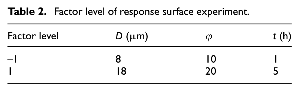
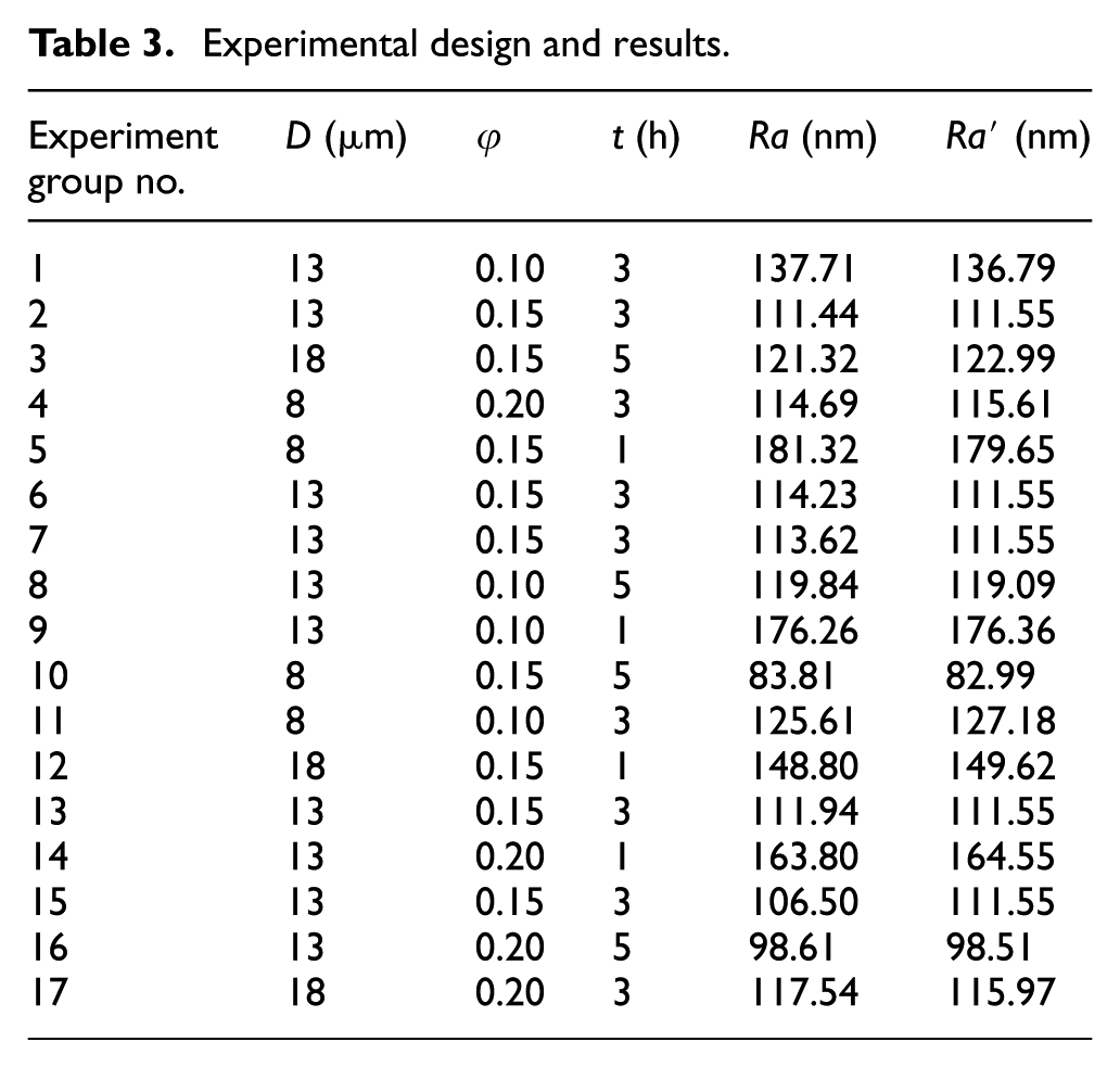
In order to comprehensively study the influence of abrasive particle size D, abrasive particle concentration φ (the ratio of the abrasive particle volume to the total volume of the abrasive flow), and the processing time t on the surface roughness Ra of the workpiece after machining and to establish a surface roughness prediction model, the interaction experiments of various factors based on response surface methodology were designed and analyzed. The Box–Behnken design is a spherical design that is compliant with rotation, and this design method can estimate interacting polynomials with fewer experiments. 26 This article uses this method to design experiments. Three factors (abrasive particle size, abrasive particle concentration, and processing time) were selected for the experiment. Tables 2 and 3 are the response surface condition level table and response surface experimental design table, respectively. The processing effect of the abrasive flow is directly related to the hardness of the abrasive particle. 27 Since the titanium alloy has a high surface hardness, silicon carbide was selected as the abrasive particles. D is the abrasive particle size, φ is the concentration of abrasive particle, t is the processing time, Ra is the measured value of the surface roughness, and Ra′ is the predictive value. The local and route loss of the abrasive flow in the constraint flow channel will cause the uneven effect of the abrasive flow on the workpiece surface. In order to reduce the influence of this phenomenon as much as possible, the position of the inlet and outlet of the abrasive flow will be changed every 0.5 h for machining.
Factor level of response surface experiment.
Experimental design and results.
Experimental results and discussions
Prediction model and reliability analysis
Surface characteristics of materials, their topography, chemistry, or surface energy, play an essential part in osteoblast adhesion on biomaterials and the quality of cell adhesion will influence the cell capacity to proliferate and differentiate in contact with a biomaterial. 28 For the surface of titanium alloy artificial joints, too large or too small surface roughness may adversely affect the adhesion of osteoblasts; therefore, it is necessary to carry out cell adhesion experiments within a certain range of surface roughness to obtain an optimal threshold value of surface roughness which could be used to guide the experiments of abrasive flow machining. According to the experimental data of the response surface, the prediction model of surface roughness in the abrasive flow machining of titanium alloy artificial joint surface using the Design Expert software is written as
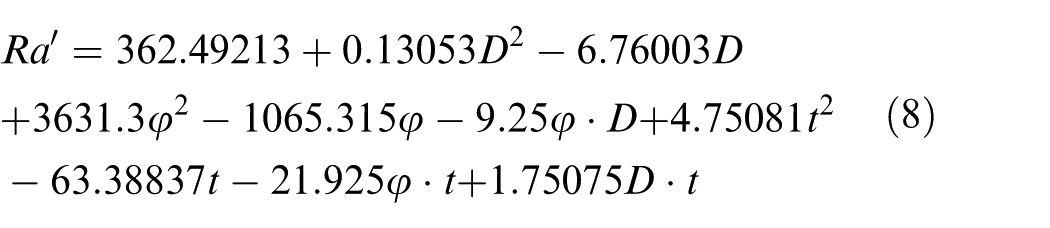
where Ra′ is the surface roughness prediction value, D is the abrasive particle size, φ is the abrasive particle concentration, and t is the processing time. The applicable range of this surface roughness prediction model is as follows: 8 μm ≤D≤ 18 μm, 0.1 ≤φ≤ 0.2, 0 h ≤t≤ 5 h.
In order to evaluate the reliability of the experimental results and the reliability of the mathematical model, significant analysis and variance analysis are required on the experimental results to test the significance of the factors and the credibility of the mathematical model. Table 4 shows the variance analysis of the response surface regression model.
Variance analysis of response surface regression model.
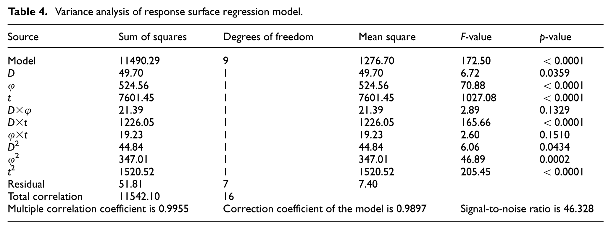
From the analysis of variance in Table 4, we can see that the model F = 172.50 > F0.01(9, 7) = 6.84 and (p < 0.0001) < 0.05, indicating that the prediction model is extremely significant. The multiple correlation coefficient is 0.9955, indicating that the predicted value is highly correlated with the measured value, and the model is well fitted. The correction coefficient of the model is 0.9897, which means that the model can explain the change of response value of 98.97%, and only 1.02% of the total variation cannot be explained by this model. The signal-to-noise ratio of the model is 46.328 (>4), indicating that the model has sufficient resolution. In conclusion, it can be seen that the prediction model is reasonable, and this model can be used to analyze and predict the surface roughness Ra of the abrasive flow machining of titanium alloy artificial joint under the experimental conditions in this article. At the same time, it can be seen from the F- and p-value that under the experimental process parameters of this article, the order of significance of the three process parameters is as follows: processing time t > abrasive particle concentration φ > abrasive particle size D. It can also be seen from Table 4 that the interaction of abrasive particle size D and processing time t (D×t) is significantly greater than the other two interactions (D×ϕ, φ×t). It indicates that the interaction of processing time and abrasive particle size may be relatively more effective during processing.
In order to further verify the reliability of the prediction model, verification experiments were performed, as shown in Table 5. Here, E is the error of the predictive value relative to the measured value. It can be found from Table 5 that the surface roughness prediction error range is 3.60%–6.32%, which proves the correctness of the prediction model and that it could be used for the prediction of surface roughness Ra of coverage constraint abrasive flow machining of titanium alloy artificial joint surface under the processing conditions of this article.
Processing parameters of verification test and experimental result comparison.
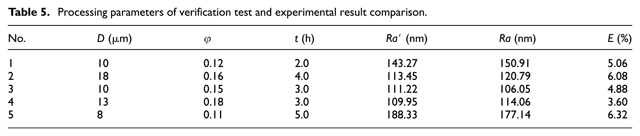
Figure 5 shows the surface micro-morphology of abrasive flow with different abrasive particle sizes after processing for 5 h at an abrasive grain concentration of 0.1. From Figure 5(a), it can be found that the surface of the rough polished titanium alloy mainly consists of convex peaks and groove structures, and the surface roughness Ra is about 230.0 nm. Figure 5(b)–(d) shows the surface micro-morphology and roughness at a position on the surface of the workpiece after machining for 5 h under the condition that the abrasive particle diameter is 18–8 μm and the abrasive particle concentration is 0.1, and the average surface roughness Ra of the workpiece after machining was reduced to 137.1, 119.8, and 95.8 nm, respectively. At the same time, it can be found that after abrasive flow machining, the number of convex peaks and grooves in the workpiece surface is obviously reduced and the surface topography is now mainly composed of pits and extruded lips formed by abrasive grains impacting the workpiece surface. Moreover, the surface is finer with the decrease in particle size than the original state. These phenomena proved the feasibility of coverage constraint abrasive flow machining of titanium alloy artificial joint surface.
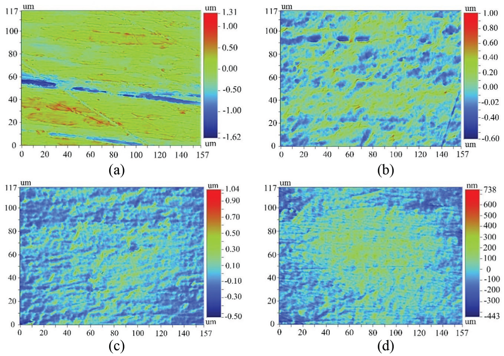
Contrast of workpiece surface morphology: (a) original surface morphology, (b) machined surface morphology with abrasive particle size 18 μm, (c) machined surface morphology with abrasive particle size 13 μm, and (d) machined surface morphology with abrasive particle size 8 μm.
Figure 6 shows the surface finish of the workpiece after 5 h of abrasive flow machining with different abrasive particle size at a concentration of 0.1. It can be seen from the figure that the original surface of the titanium alloy workpiece is not clearly imaged; however, after 5 h of machining with abrasive flow, the clarity of text reflection on the surface of the workpiece is increased and the surface finish is improved; the surface finish is improved with the reduction in abrasive particle size. It illustrates that abrasive particle size may play an important role in the abrasive flow machining and affects the surface finish of the titanium alloy artificial joint workpiece.
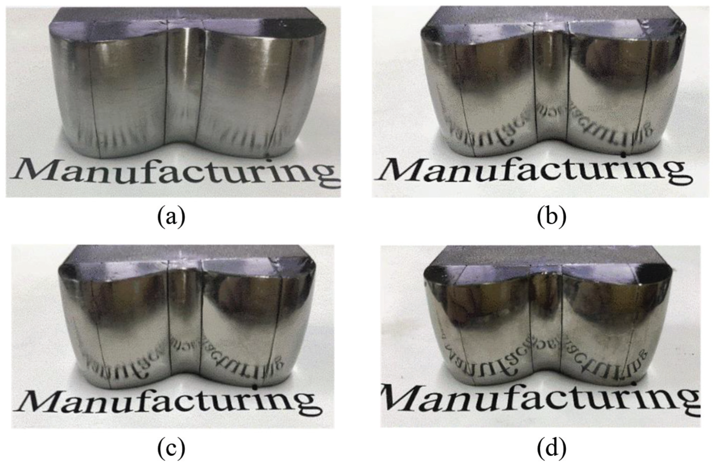
Contrast of workpiece surface finish: (a) original surface, (b) process 5 h with particle size 18 μm, (c) process 5 h with particle size 13 μm, and (d) process 5 h with particle size 8 μm.
Effect of abrasive particle size and processing time on surface roughness
The selection of abrasive particle size is related to the processing requirements. In the abrasive flow machining, the larger particles are mainly used for deburring and rough machining, and the smaller particles are used for finishing polishing. This experiment studies the polishing effect of the abrasive flow on the workpiece surface with a smaller particle size range; therefore, the workpiece surface roughness Ra has been pre-polished to about 230.0 nm. With reference to the research group and the research results of abrasive flow machining, silicon carbide with particle sizes 8, 13, and 18 μm were selected for experiments.
Figure 7 shows the response surface of abrasive particle size D and the processing time t to the average surface roughness Ra of the workpiece when the abrasive particle concentration φ = 0.15. It can be seen from Figure 7 that under the processing conditions of abrasive particle size of 8–18 μm, processing time of 0–5 h, and abrasive particle concentration of 0.15, the surface roughness Ra decreases with the decrease in abrasive particle size and decreases with the increase in processing time. It can be further seen that the abrasive particle flow with a larger particle size has a greater effect on the initial processing period (0–2 h) than the abrasive particle flow with a smaller grain size. With the increase in processing time, the workpiece surface roughness Ra gradually tends to a processing limit, and the smaller the particle size, the smaller the limit of surface roughness Ra. The surface roughness Ra can reach to about 80 nm after 5 h of abrasive flow machining with a particle size of 8 μm. According to Oka’s erosion model, the smaller the particle size of abrasive particles, the smaller the material removal caused by the impact of abrasive particles on the workpiece surface at the same impact speed, the finer the micro-scratches produced by the grinding action of the abrasive flow, and the better the surface quality of the workpiece. At the same time, it can be seen that the change trend of the response surface is obvious, indicating that the interaction of abrasive particle size D and processing time t (D×t) has a significant effect on surface roughness. Therefore, this combination can be prioritized during the process optimization, and abrasive particle with smaller particle sizes should be used to obtain a better surface quality.
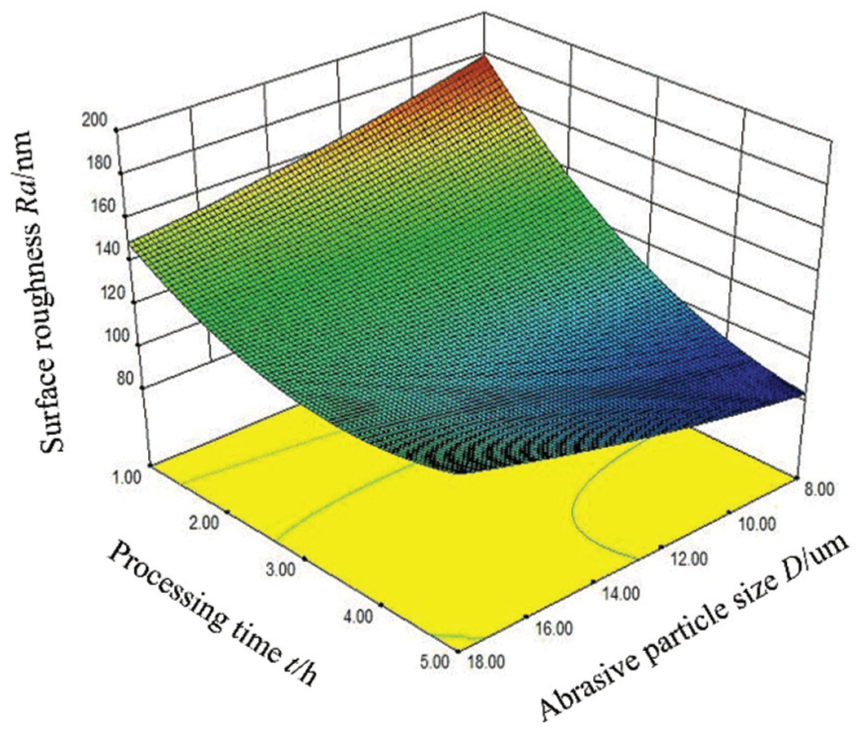
Effect of particle size and processing time on surface roughness.
Effect of abrasive particle concentration and processing time on surface roughness
According to the previous study, 29 the abrasive particle concentration of 0.1–0.2 has a good processing effect, so this concentration range was selected for the machining experiment to study the effect of abrasive particle concentration on the processing effect of abrasive flow.
Figure 8 shows the response surface of abrasive particle concentration φ and processing time t to the average surface roughness Ra of the workpiece when the abrasive particle size D = 13 μm. It can be seen from Figure 8 that under the processing conditions of abrasive particle size of 13 μm, processing time of 0–5 h, and abrasive particle concentration of 0.1–0.2, the surface roughness of the workpiece decreases as the abrasive particle concentration increases. After processing for 5 h at an abrasive concentration of 0.2, the surface roughness Ra of the workpiece can reach to about 98 nm. Under the same conditions, the surface roughness Ra can reach to about 120 nm when the abrasive particle concentration is 0.1. It can be further seen that in the same processing time, the greater the concentration of abrasive particle, the greater the degree of surface roughness reduction and the higher the processing efficiency. This phenomenon may be related to the number of abrasive particles participating in the cutting at the same time. When the abrasive particle size and the abrasive particle speed are constant, the abrasive flow with a larger concentration will have a larger number of abrasive particles per unit time that impact the workpiece surface, and consequently, the formed cutting amount is also larger and the surface micro-cutting traces are finer; therefore, it will have a comparatively finer processing quality and a higher processing efficiency. However, if the concentration is too large, the flow viscosity of the abrasive flow will be too high, which will reduce the flowability of the abrasive flow in the constraint flow channel and affect the processing effect.
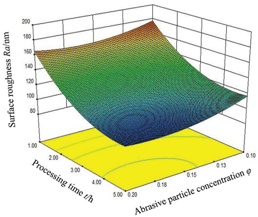
Effect of particle concentration and processing time on surface roughness.
Effect of abrasive particle size and abrasive particle concentration on surface roughness
Figure 9 shows the response surface of abrasive particle size D and abrasive particle concentration φ to the average surface roughness Ra of the workpiece when the processing time t = 5 h. It can be seen from Figure 9 that under the conditions of abrasive particle size of 8–13 μm, abrasive particle concentration of 0.1–0.2, and processing time of 5 h, the greater the concentration of abrasive particles at the same particle size, the smaller the surface roughness of the workpiece and the finer the machined surface. At the same time, it can be found that at the same abrasive particle concentration, the smaller the abrasive particle size, the smaller the workpiece surface roughness. It can be concluded that the workpiece has a better surface quality under the conditions that the processing time is sufficient, the abrasive particle diameter is smaller, and the abrasive particle concentration is larger. This phenomenon is in line with Oka’s erosion model. Under the conditions that the processing time is sufficient and the flow rate of the abrasive flow is constant, the smaller the size of the abrasive particles, the smaller the removal amount of the impact wall formed by a single abrasive particle, the smaller the micro-cutting trace of the workpiece when reaching the machining limit. At the same time, when the concentration of abrasive particles is larger, the number of abrasive particles involved in the cutting increases, and the micro-cutting traces will be more compact, which will help to form a better surface quality. Besides, it can also be found that the entire response surface of the interaction of abrasive particle size D and abrasive particle concentration φ (D×φ) is relatively flat, indicating that this interaction has little effect on the surface roughness. Thus, it is not recommended to prioritize the interaction of particle size and concentration in the actual process optimization.
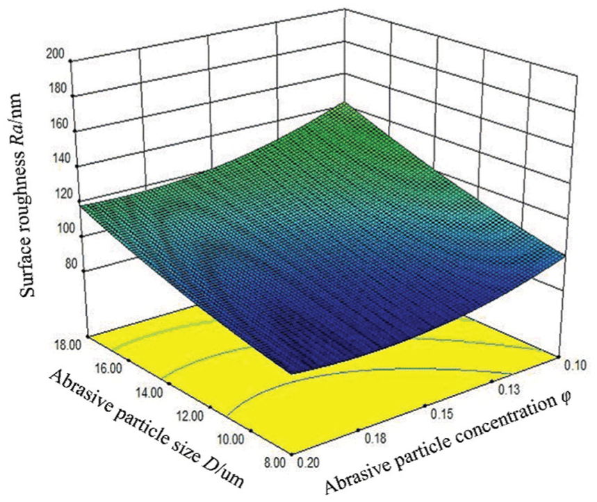
Effect of particle size and concentration on surface roughness.
Surface roughness analysis of different regions of workpiece
For the surface regions I, II, III, IV, and V, the processing effect of abrasive flow is different. The surface roughness of the five areas was recorded every hour at the processing conditions of abrasive particle size of 18 μm and abrasive grain concentration of 0.1 in a total processing time of 5 h, and the results are shown in Figure 10. Figure 10 shows that the surface roughness of the workpiece in all five regions has decreased, the surface roughness has declined in the first 2 h, and the decreasing trend is obviously reduced after 2 h until it finally tends to reach a stable value. The surface roughness in the I and V regions was basically the same which decreased from 230 to 147 nm. The surface roughness in the II and IV regions was basically the same and decreased from 230 to 130 nm. The surface roughness Ra of III region decreased from 230 to 126 nm which has the best processing effect. The surface roughness value Ra on different regions of the workpiece was dispersed and this phenomenon may be due to the uneven distribution of the dynamic characteristics of abrasive flow on the workpiece surface, such as velocity distribution, dynamic pressure distribution, turbulent kinetic energy distribution, and abrasive particle volume fraction distribution which could affect the removal effect of abrasive particles when impacting the workpiece surface. Those dynamic characteristics will directly affect the force of the abrasive particle in the viscoelastic media, resulting in uneven removal effect when the abrasive particles impact the workpiece surface in different regions.
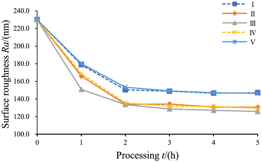
Surface roughness changes in each region of abrasive flow machining.
Aiming at the phenomenon of uneven processing effect, the structure of the profiling flow channel could be optimized as follows: (1) set abrasive flow compensation inlet in the poorly processed areas; (2) design a non-eq9 height channel to increase the flow rate in poorly processed areas; (3) set gas compensation inlet to improve the uniformity of velocity distribution and dynamic pressure distribution of abrasive flow; (4) design a processing flow channel with disturbance structures to enhance the randomness of abrasive flow thereby improving the processing uniformity; and (5) design a processing flow channel with a texture similar to that of a golf ball surface which may have a drag reduction effect. The ultimate goal of flow channel structure optimization is to improve the turbulent flow characteristics of the abrasive flow in the flow channel, such as increasing the turbulent energy of the abrasive flow as much as possible, increasing the uniformity of velocity and dynamic pressure of the abrasive flow in various regions of the workpiece surface, and reducing the local loss and loss of the abrasive flow.
In this article, the processing temperature and inlet velocity were kept constant during the experiments; however, both processing temperature and inlet velocity are important factors affecting the processing effect. In the conventional abrasive flow machining, different processing temperatures have different processing effects on the same workpiece sample. When the temperature is too high, the viscosity of the medium is excessively reduced, thereby causing the abrasive particle to roll back and reducing the processing efficiency. 30 The inlet velocity directly affects the distribution of the turbulent flow energy, velocity, and dynamic pressure of the abrasive flow on the workpiece surface, which would affect the machining effect. 31 Compared with the conventional abrasive flow machining, the soft abrasive flow has a lower viscosity, and the tendency of the abrasive particles to roll back in the flow channel is greater. Therefore, the processing temperature and inlet velocity could be further studied and expanded to improve the applicability of the prediction model.
Conclusion
The following conclusions can be drawn from this study:
This article demonstrates that under the experimental conditions, at the same flow velocity, the smaller the abrasive particle size and the greater the abrasive particle concentration, the better the processing effect on the Ti-6Al-4V titanium alloy artificial joint workpiece. As the time of processing increases, the surface roughness of the workpiece gradually decreases. After a certain time of processing, the surface roughness decreases to its extremity. However, continuous processing leads to an inconspicuous effect.
After abrasive flow machining, the grooves and peaks on the surface of the titanium alloy workpiece were significantly reduced, and the micro-morphology of the surface was mainly micro-pit and extrusion lip.
After abrasive flow machining, the machining surface roughness Ra varies in different regions of the titanium alloy artificial joint workpiece. The surface roughness of the I and V regions (lateral epicondyle regions) shows similar downward trends, and the surface roughness of the II and IV regions (lateral condyle regions) also shows similar downward trends. As for the value of processing extremity roughness Ra, I and V regions > II and IV regions > III regions (intercondylar notch region), and the III region achieves the best processing effect. The discovery of this phenomenon can provide a basis for an optimal design of the constraint flow channel structure.
The three-factor and three-level response surface experiment was designed under the processing conditions of the abrasive particle size of 8–18 μm, the abrasive particle concentration of 0.1–0.2, and the processing time of 0–5 h. Based on the experimental results, the prediction model of surface roughness Ra is obtained, and its correctness is verified by the variance analysis and verification test. This prediction model contributes to guiding the optimization of the process of coverage constraint abrasive flow machining of titanium alloy artificial joint surface under the experimental conditions.
Footnotes
Appendix 1
Declaration of conflicting interests
The author(s) declared no potential conflicts of interest with respect to the research, authorship, and/or publication of this article.
Funding
The author(s) disclosed receipt of the following financial support for the research, authorship, and/or publication of this article: This work was supported by National Natural Science Foundation of China (Nos. 51575493 and 51705462), Zhejiang Provincial Basic Public Welfare Research Project (LGG19E050025), Zhejiang Provincial Natural Science Foundation of China (Nos. LY15E050020 and LQ16E050012) and Talent Project of Zhejiang Association for Science and Technology (No. 2018YCGC016).