
Abstract
To simulate the deformations of the strip peen formed plate more realistic, and using low computational resources, a strategy combining analytical and finite element methods is proposed in this article. First, the internal stresses in the target induced by single shot impact are calculated with expanding cavity model. Second, the stress field of single shot impact is used to derive the stress field of multiple shot impacts by considering the overlaps of adjacent shot impacts. Third, the calculated stress field is introduced to the finite element model to obtain the resultant shape of the plate. The shot dimple distribution in reality is detected and fitted with normal distribution function. The random distribution of the positions of shot impacts is involved in the simulation to make the simulation more realistic. In the finite element model, the plate is modeled with shell element to reduce the demand of the computational resources. The simulated shapes of the plate under different peen forming parameters are compared with the scanned three-dimensional experimental shapes with the same forming parameters. The comparison shows that the simulated shapes are in good agreement with the experiments.
Introduction
Shot peen forming is a cold working process to shape curved metal parts. It is primarily used in the aerospace industry for shaping large sections such as wing panels.1,2 In the forming process, numerous shot impacts on the component surface with high speed cause the surface to deform plastically. The plastic deformation results in a residual compressive stress distribution in the surface layer and a curvature deformation of the component.3,4
To control the process, many control parameters related to both shot peening machine and target are monitored. The key parameters that determine the resulting shape are shot type, pneumatic pressure for driving the shots, relative moving speed of the nozzle, shot flow from the nozzle, target material properties, peened region on the target and so on. These parameters are usually indicated with shot velocity, peening coverage, Almen intensity and so on. The relationships between the forming parameters and the resulting shape are usually obtained by a large number of costly experiments.
Several theoretical works are developed to understand the process. Al-Hassani 5 expressed the induced stress distribution with a cosine function. Tan et al. 6 empirically modeled the relationships between residual stresses and peening parameters with sinusoidal decay function. Li et al. 7 developed a simplified analytical model to calculate the residual stress field due to shot peening with assumptions that, after 100% coverage, the plastic deformation is steady and continuous and the work piece is still flat. Miao et al. 8 followed Li’s models to calculate the induced stress in a semi-infinite body, and used Guagliano’s 9 model to calculate the residual stress in the Almen strip. Zhang et al. 10 developed a cross-sectional linear indentation coverage method by considering regular indentation and coverage.
Finite element (FE) simulation is an important method to predict the peening stresses under different peening parameters. Bagherifard et al. 11 made a review of different multiple impacting patterns. However, those simulations are limited to a few shot impacts. Wang et al. 12 presented a FE analysis for modeling up 1000 random impacts. In the real-life shot peen forming, a large component may be peened with millions of shots.
Several numerical tools were developed to obtain the formed shape of the large components using equivalent loading methods. Grasty and Andrew 13 proposed an equivalent method to simulate the impacting effect of a large number of shots in which the surface layers of the plates were subjected to a squeeze pressure to produce a small plastic deformation similar to shot impacting. Levers and Prior 14 proposed a static analysis method to simulate the peening deformation by introducing the material coefficient of thermal expansion and temperature profiles into the elements. Wang et al. 15 developed the thermal loading model by applying a loading unit to induce an equivalent plastic layer in a plate. Han et al. 16 proposed that, in the first stage, the residual stress/strain profiles under the particular set of peening parameters were identified by simulating the peening process for a small-scale sample, and then in the second stage, the obtained stress/strain profiles were applied to the entire component to obtain the final shape. Gariépy et al. 17 and Faucheux et al. 18 obtained the residual stress profiles by simulating the practical peening processes, and then assigned the stress profiles to plates modeled with composite shell element. In the above equivalent numerical methods, the stress and strain distributions induced by shot impacts are averaged locally. Bhuvaraghan et al. 19 used a discrete and FE method to obtain the more realistic residual stress and plastic strain distributions induced by a large number of shot impacts. The simulation time in FE model has been reduced by avoiding contact detection.
In this article, aiming to predict the peen formed shapes of plates under more realistic peening conditions and costing less computational time, a combined method is proposed. First, an analytical model is used to calculate the residual stress field of single shot impact and multiple shot impacts. Then, the calculated stress field is assigned to FEs to obtain the resulting shape. The numerical predictions are compared with experimental results.
Experiment
In the shot peen forming process, the wing skin hanged vertically on carrier is peened within strip areas by passing through the peening enclosure. 20 The process also can be implemented by controlling the peening nozzles moving over the target surface. 21 Varying peening intensities are selected on the strip areas depending on the desired curvatures. 22
To investigate the effect of strip peening treatment on the plate deformation, experiments were performed on the aluminum alloy 2024-T351 (AA2024-T351) plates with dimensions of 200 × 200 × 5 mm, as shown in Figure 1(a). The strip peening treatment is imposed in the center strip area aligned with the rolling direction of the plate. The experiments are performed on the Wheelabrator MP20000 Aircraft Wing Peening System with standard shot of APB1/8.
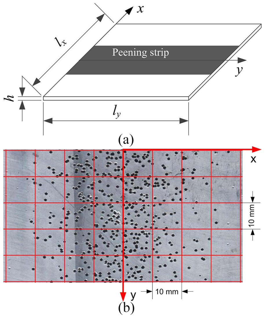
(a) Schematic view of experimental specimen and (b) shot dimple distribution in peening strip.
The distance between the peening nozzle and the plate is 200 mm. The rate of shot flow is 10 kg/min. The pneumatic pressure is 0.3 MPa. The average shot velocity when leaving the nozzle is measured with the high-speed photographic setup attached to the MP20000, which is 40 m/s. The relative moving speeds of the nozzle of four experiments are 2, 4, 6 and 8 m/min, respectively.
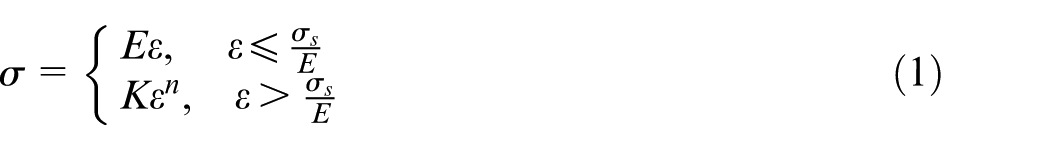
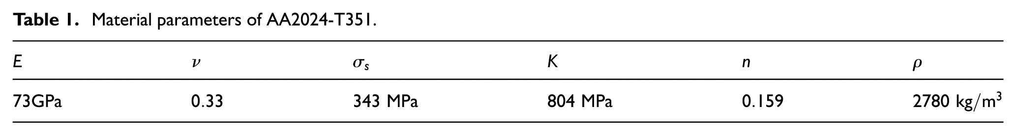
The target material is aluminum alloy 2024-T351, which is usually used for aerospace application requiring high strength to weight ratio, as well as good damage tolerance. The true stress–true strain curves of AA2024-T351 were fitted using the power-law hardening model in equation (1) from conventional tensile test by Heerens et al. 23 The material parameters of AA2024-T351 are listed in Table 1
Material parameters of AA2024-T351.
The resulting shape of the plate with striped peening area is not simple spherical shape as the uniformly peened shape. The complex resulting shape is hard to be detected with limited measurements of local arc height. The shape of the plate is measured with three-dimensional scanning device HandyScan300 of CREAFORM.
The shot dimple distribution in the
In order to detect the dimple distribution in
where
Expanding cavity model
Single shot impact model
The process of one shot with velocity
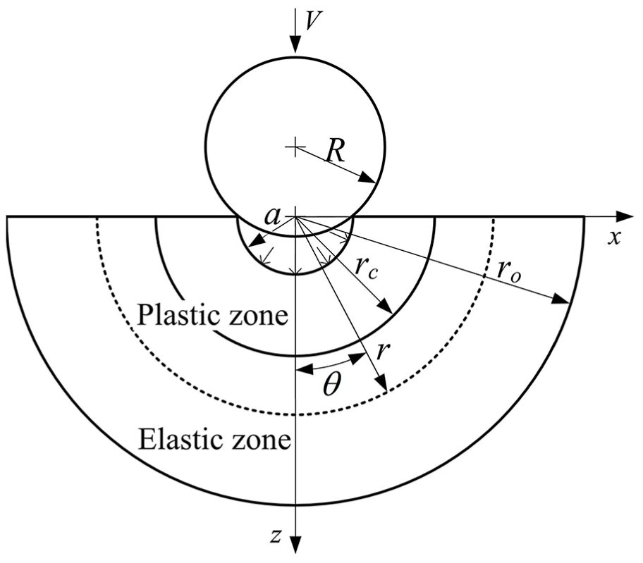
Schematic view of shot indentation with cavity radius
The stress components in the target during loading for power-law hardening plastic material are derived from the work of Gao et al.,
26
given in equations (3)–(7). In the spherical coordinate system, the radial stress
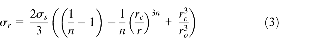
where
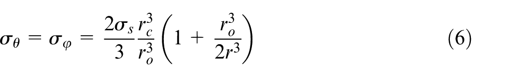
The hoop stresses
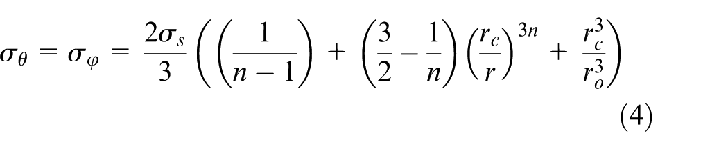
The radial stress
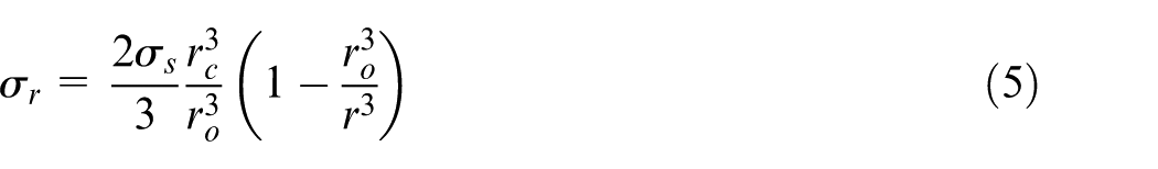
The hoop stresses
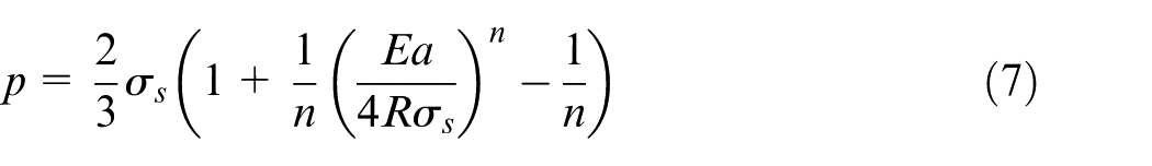
The mean contact pressure between the shot and the target is
Particularly, in shot peening process, the initial kinetic energy of one shot is mostly converted into elastic-plastic work during the impact. The parameters about the shot can be related to the shot dimple as
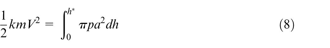
where
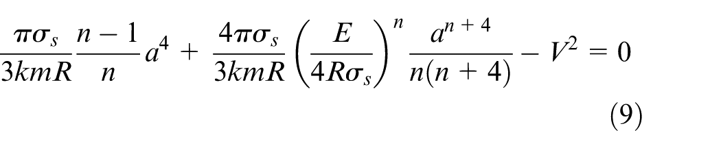
The shot dimple radius for certain peen forming parameters and conditions can be obtained numerically with equation (9). Then, the outer radius of plastic zone is
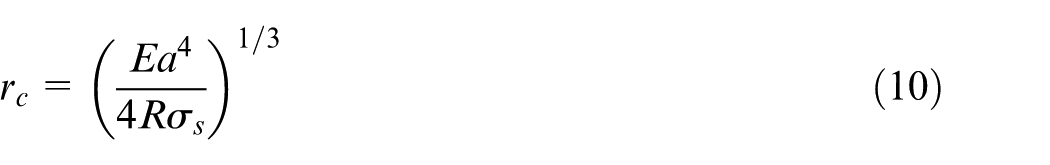
Substituting
where
Multiple shot impacts model
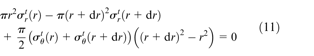
For two shots impacting on the target with a separation distance
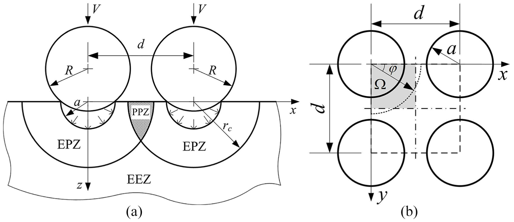
Schematic view of (a) two shots impacting onto the target with a separation distance
Assuming multiple shot impacts are imposed at the regular positions as shown in Figure 3(b), the stress fields induced by adjacent impacts would overlap each other. Since the plastic zone of each impact is relatively small and subsequent impact is hard to yield the former hardened material, the overlapping of adjacent stress fields is assumed to only take place in EEZ. In EEZ, the stress field is the sum of adjacent stress fields. In the EPZ and PPZ, the stress fields remain in the state of single shot impacting.
Numerical simulation
In the previous section, the peening stresses of single shot impact are calculated with expanding cavity model in the polar coordinates. To investigate the deformation of a plate peened by many shots, FE simulation is needed. In the cavity model, a symmetry constraint is applied on the peened surface of the target. First, a FE model of single shot impact is used to simulate the internal stresses of the target when removing the symmetry constraints on the peened surface. Second, the deformations of a shell strip and a solid strip involving the calculated peening stresses are compared. Finally, the deformations of plates simulated with realistic parameters are compared with the experimental results. The material under study of the numerical simulation is the same as the material of the experiments.
A clear distinction is made at this point between stresses in the target material. The stresses after loading of the expanding spherical model is called expanding stresses and the stresses after unloading is called expanding residual stresses. The stresses after removing the symmetry constraint on the peened surface is called transresidual stresses. 8 The stresses after shot peening treatments and before the release of the rigid constraints on the component is called induced stresses.
Single shot peening model
In the simulation procedure, the expanding residual stresses are introduced to the FE model to obtain the transresidual stress field after removing the symmetry constraint on the peening surface. The expanding residual stresses are calculated from equations (3)–(11) in software MATLAB 7.10. 28 The calculation parameters are the same as the parameters of the experiments in the “Experiment” section. Then, FE simulation is performed in software ABAQUS 6.10. 29
The FE model shown in Figure 4 is used for the single shot peening simulation. The following dimensions are selected for the FE model: height
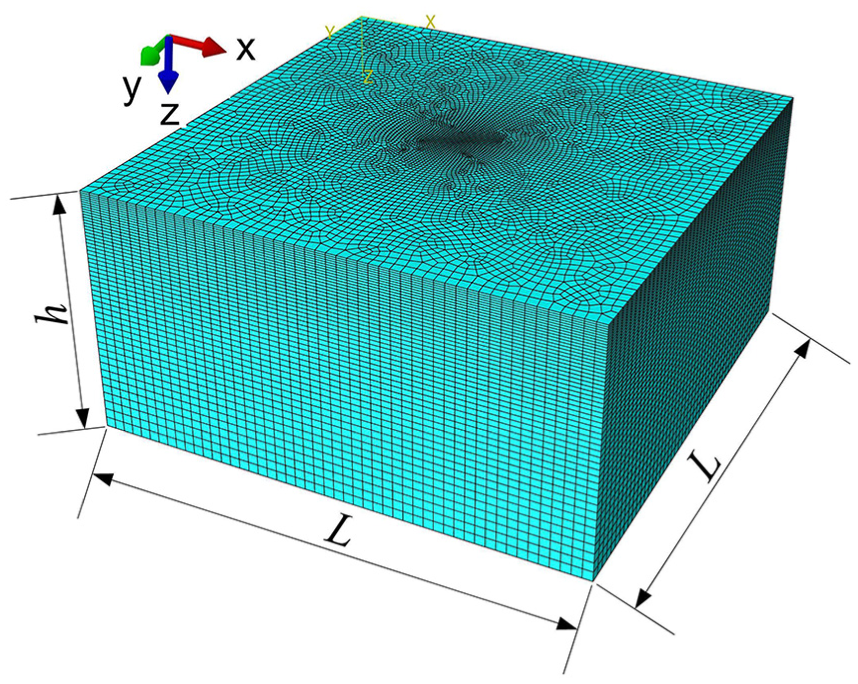
Discretized geometries of target in the single shot peening model.
The expanding stresses and the expanding residual stresses were calculated in the spherical-polar coordinates. To introduce the expanding residual stresses to the FE model as initial stresses, the stresses in the spherical-polar coordinates need be transformed to rectangular coordinates with
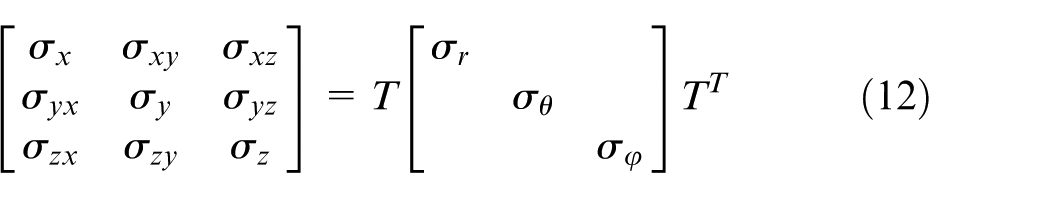
where
On the FE model, the symmetry boundary conditions are imposed on the
Model of strip peened regularly
The deformations of rectangular strips peened regularly on the top surface are simulated. As shown in Figure 5, the strip dimensions are
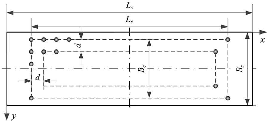
Shot distribution and dimensions of peened strip with
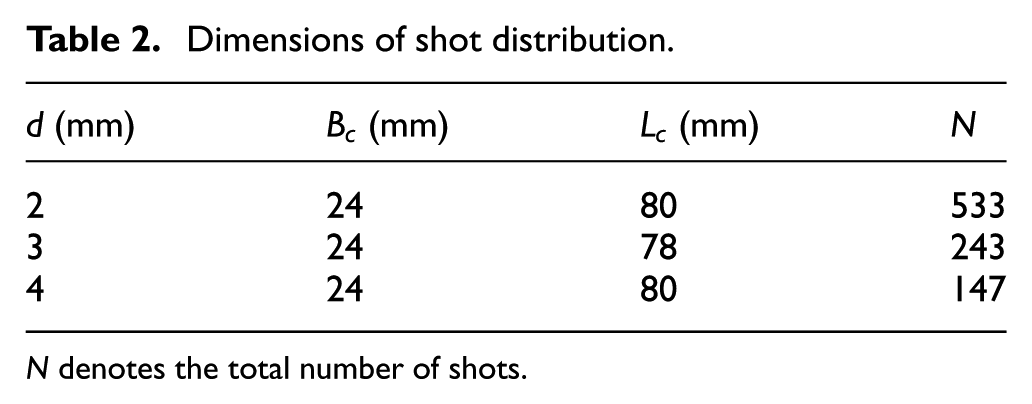
Dimensions of shot distribution.
Strip model with solid element
The strip is modeled with solid element C3D8R in Abaqus with element dimensions of 0.2 × 0.2 × 0.2 mm. The initial stresses in the elements of the strip are the expanding residual stresses calculated from the expanding cavity model. The overlapping of the stress fields of adjacent shot impacts are considered as proposed in the “Multiple shot impacts model” section. The simulation procedure is carried out by two static/general steps. In the first step, the symmetry boundary conditions are imposed on the
The resulting shapes of the strips under different indenting gaps
Strip model with shell element
The strip is further modeled with shell element S4R in Abaqus with element dimensions of 0.2 × 0.2 mm. The shell has a constant thickness of 5 mm and 11 Simpson integration points through thickness. The reference surface of the shell element is taken to be the bottom surface (
where
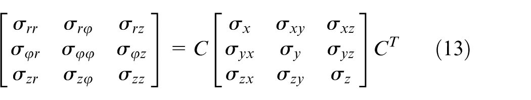
In the cylindrical-polar coordinates, removing the symmetry constraint on the peened surface of the expanding model, the expanding residual stress in the

where values of
In accordance with Hooke’s law, the relaxation values in the radial and hoop directions in the cylindrical-polar coordinates can be calculated as
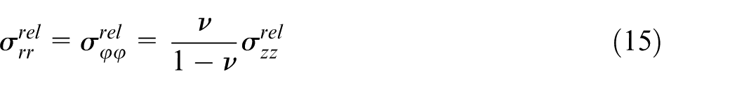
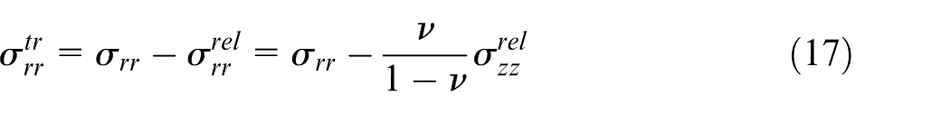
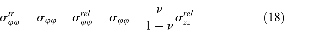
Then, the transresidual stresses of one shot impact can obtained as

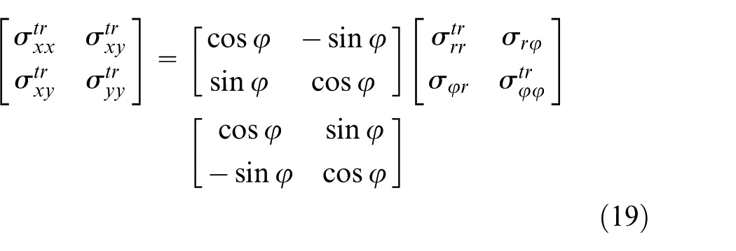
Neglecting the relaxation of the shear stresses, the in-plane transresidual stresses in the rectangular coordinates can be calculated from the stresses in the cylindrical-polar coordinates as
Then, the induced stresses are calculated by considering the overlapping of the stress fields of adjacent shot impacts proposed in the “Multiple shot impacts model” section. The induced stresses are introduced to the section points of the shell element along thickness. In the simulation procedure, the displacements of node (0, 0, 0) are fixed, the node (
The resulting shapes of the shell element strip under different indenting gaps (Table 2) are measured along the longitudinal centerline of the strip. The values of the relaxation parameter
Model of plate peened in reality
In this section, a FE model is proposed to simulate the deformation of a plate peened with the real peening parameters as the experiments in the “Experiment” section. In reality, the locations of the shot impacts are random as shown in Figure 1. In the experiments, the shot dimple distribution under different peening parameters are fitted with normal distribution function in the transverse direction of the peening strip. Based on the values of the fitting constants of the experiments, the simulating positions of the shot impacts on the plate are obtained numerically with the random functions
Figure 6 shows the discretized geometries of the plate modeled with shell element S4R in the software Abaqus 6.10. The dimensions of the elements in the middle region are 0.4 × 0.4 mm. A low element density is meshed in the both sides of the plate with elements of maximum dimensions of 5 × 5 mm. Boundary conditions (Figure 6) are chosen to present the rigid body motion of the plate.
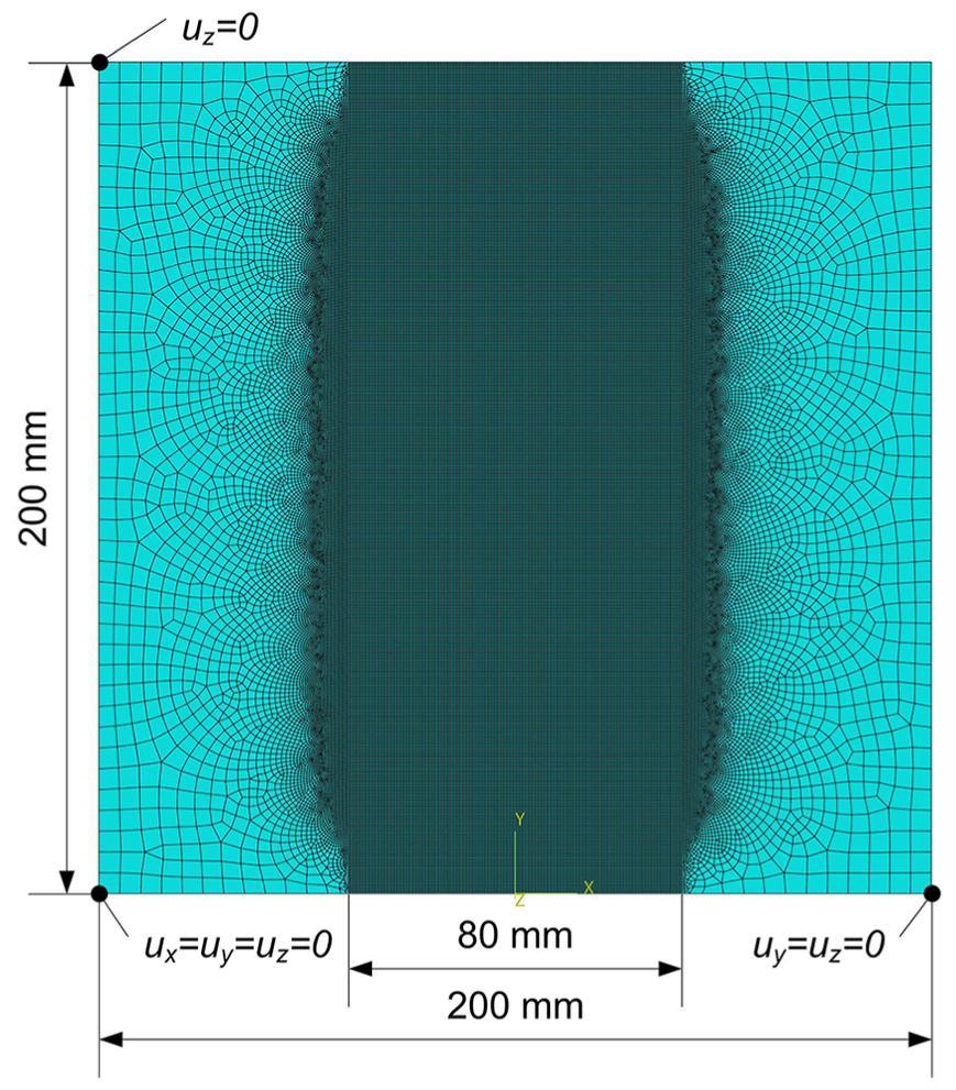
Discretized geometries of the plate with side length of 200 mm.
The induced stresses calculated with the algorithm mentioned in the “Strip model with shell element” section are introduced to the plate model as initial stresses of the FE element. The assignment of the initial stress is carried out by the subroutine SIGINI of Abaqus 6.10. The resulting shape of the plate is obtained by a static/general simulation step with nonlinear solutions. The resulting shapes under different peening parameters are compared with the scanned experimental shapes.
Results and discussion
Internal stress profiles
In the “Single shot impact model” section, the expanding cavity model was proposed to calculate the expanding stresses and the expanding residual stresses of single shot impact. With the peening parameters and the material properties of the experiments in the “Experiment” section, the radial and hoop stresses of loading (expanding stresses) and the radial and hoop stresses of unloading (expanding residual stress) in the spherical-polar coordinates are calculated as shown in Figure 7(a). The equivalent stresses of loading and unloading are shown in Figure 7(b). From the expanding cavity model, there are no values of the stresses in the region of the internal cavity with radius of
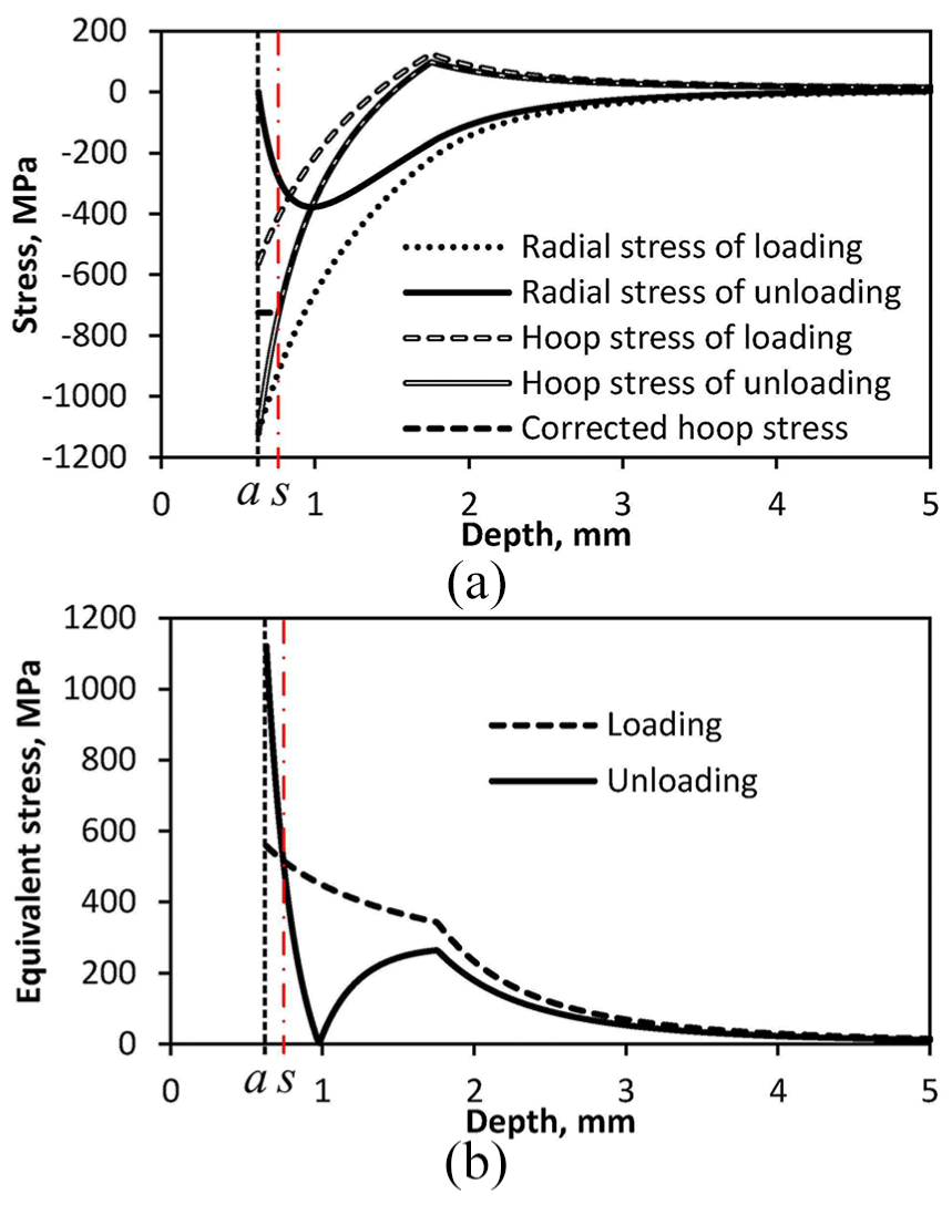
(a) Radial and hoop stresses and (b) equivalent stresses of loading and unloading in the cavity model.
Comparing the stresses of loading and unloading, it can be seen that the radial stress decreases after unloading while the hoop stress increases. Since the reverse yielding when unloading is neglected in the expanding cavity model, the unloading equivalent stress exceeds the values of loading in the surface layer with depth of
In the “Single shot peening model” section, the expanding residual stresses of single shot impact are introduced to the FE model to obtain the transresidual stresses. In the region of the internal cavity, the expanding residual stresses are set to be equal to the stresses on the internal cavity surface. Figure 8(a) shows the initial Mises stress field and initial stress in the
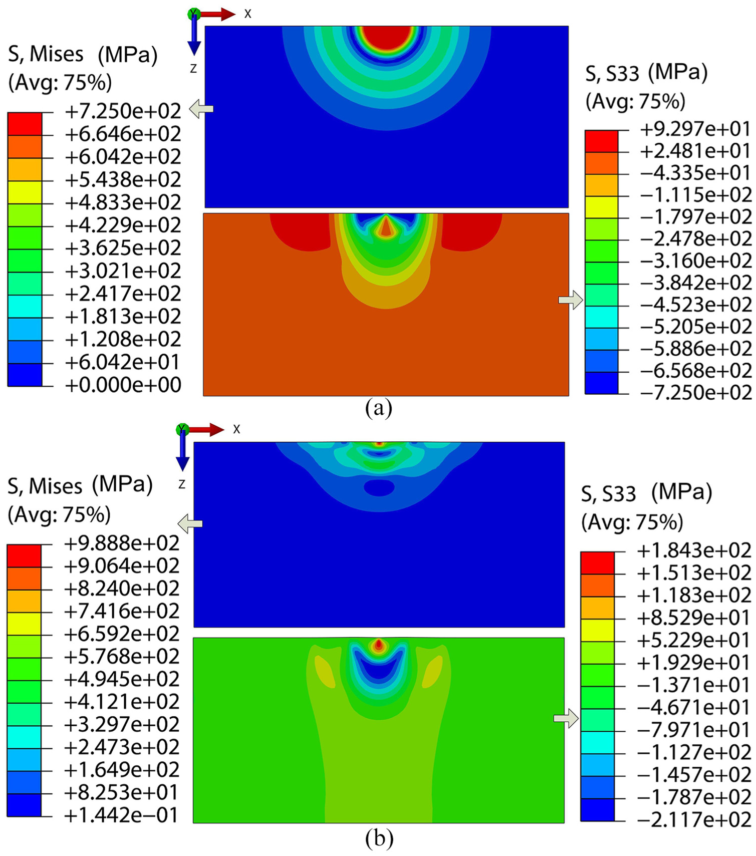
(a) Initial Mises stress field and initial stress in
Figure 9(a) and (b) compare the initial stresses and the residual stresses along the vertical centerline of the
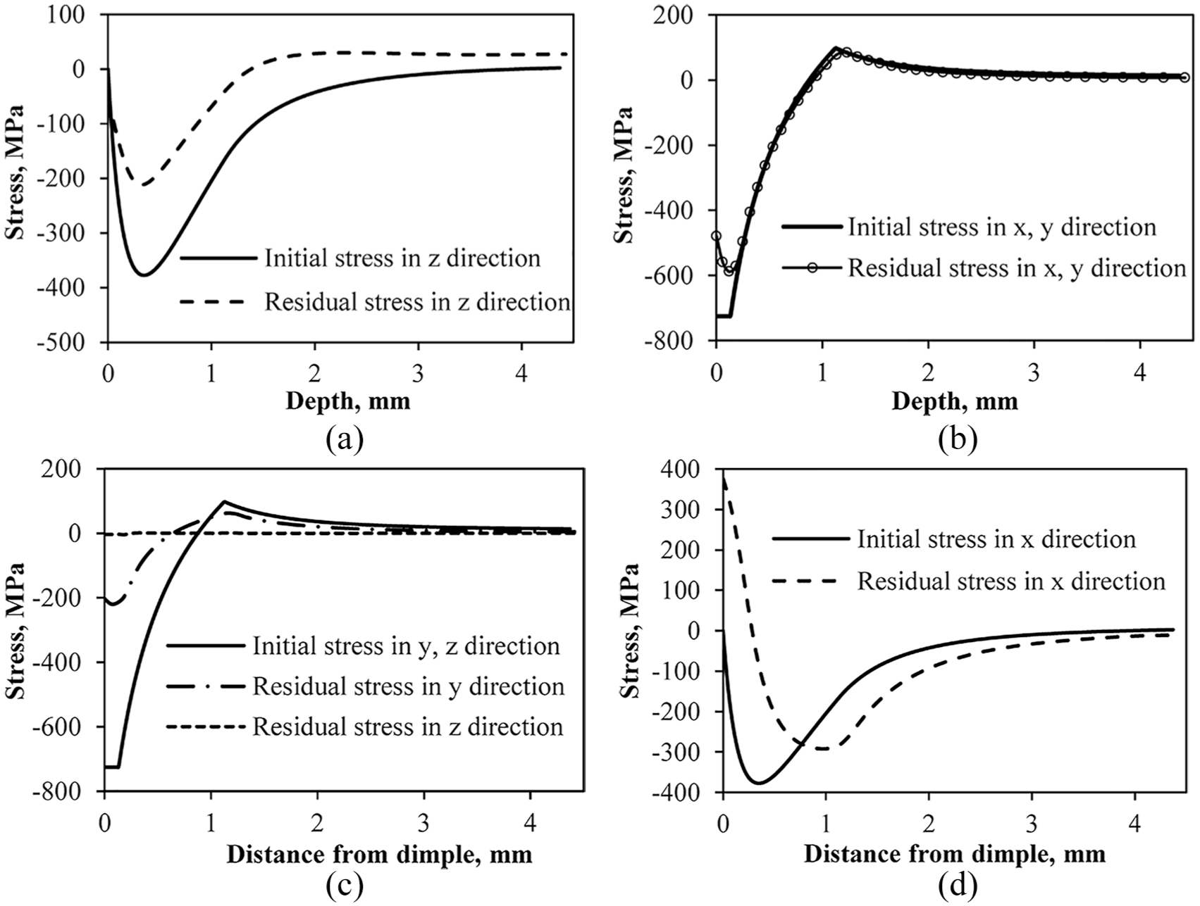
Initial and residual stresses (a) in
To simplify the analysis, the deformations of the material in the simulation were considered in the elastic region, which leads to irrational tensile stresses in a tiny region near the peening point, as shown in Figures 8(b) and 9. Since the region involving the irrational tensile stresses is very small compared with the target, its influence on the macro-deformation of the target can be neglected.
Resulting shape of regularly peened strip
In the “Strip model with solid element” section, the resulting shapes of the strips under different peening parameters are obtained by introducing the overlapped expanding residual stresses to the solid elements. In the “Strip model with shell element” section, the resulting shapes of the strips corresponding to different peening parameters are obtained by introducing the overlapped transresidual stresses to the shell elements.
Figure 10(a) shows the initial Mises stress field on the top surface (
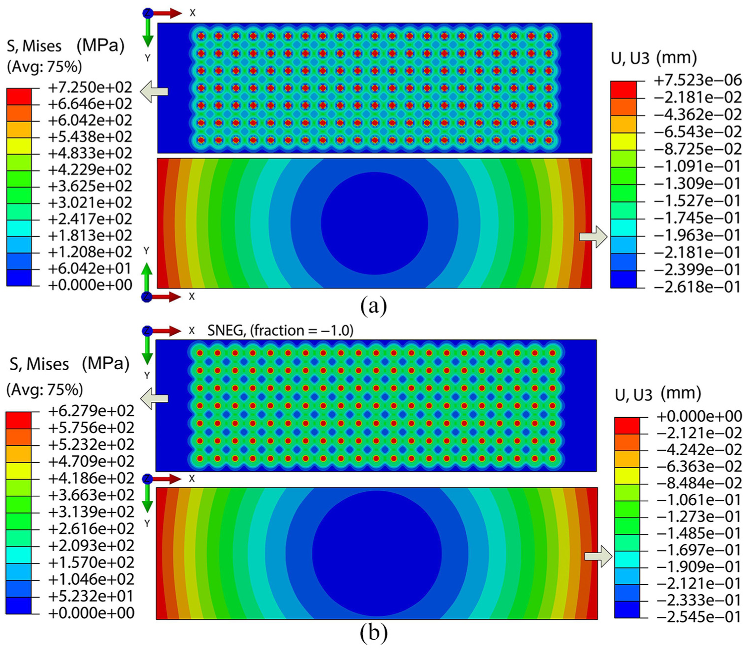
(a) Initial Mises stress field on the top surface (
Along the longitudinal centerline on the bottom surface of the solid element strip and the longitudinal centerline of the shell element strip, the resulting shapes are compared between the two different element models. Figure 11(a) shows the comparisons of the resulting shapes between the solid element strip and shell element strip with relaxation ratio
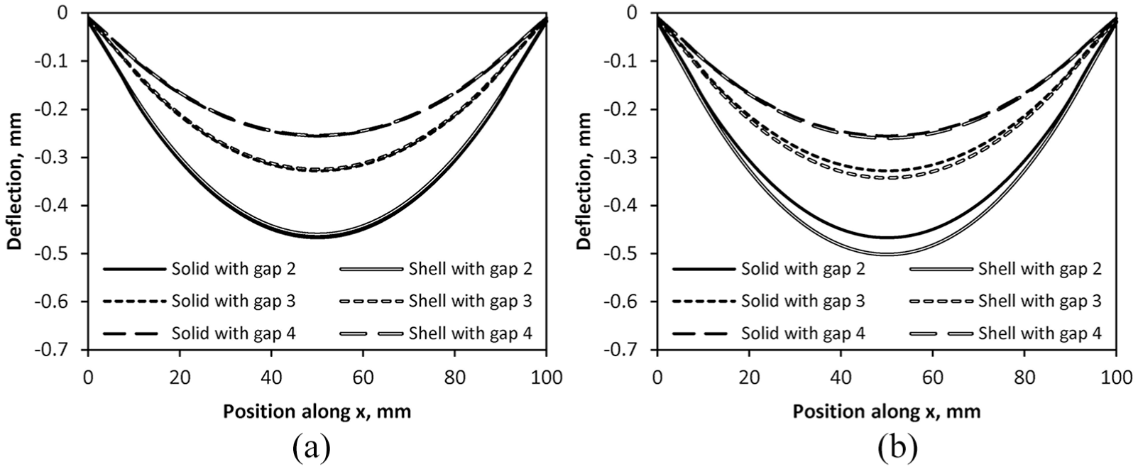
Comparison of the resulting deflections of the shell element strip and the solid element strip along the longitudinal centerline. The values of the relaxation ratio
It can be seen that under different indenting gaps, the resulting shapes of the solid element model and the shell element model agree with each other when
The above comparisons show that the shell element model combined with the algorithm proposed in the “Strip model with shell element” section can be used to simulate the deformations of shot peen formed plate.
Shot dimple distribution
The mean mass of one APB1/8 shot was measured on METTLER TOLEDO analytical balances. The mean mass of one shot is 0.12975 g. According to the shot flow rate and the nozzle moving speed, the total number of the shot per 10 mm length of peening trajectory can be calculated, as shown in Table 3. The dimple number per 10 mm length of peening trajectory on the peened plate was also counted and compared with the theoretical number. The counted numbers are smaller than the theoretical number. The deviation between the counted number and the theoretical number increases with the decrease of the nozzle moving speed. The differences might be attributed to the following:
The peening coverage increases with the decrease of the nozzle moving speed, which leads to the number of shot repeatedly impacting on the same region increase.
The selected representative region for counting the shot dimple number is limited and some shot maybe impacted out of the region.
There are some deviations on the calculation of the theoretical shot number and on the realistic shot number ejected out of the nozzle.
Parameters of shot distribution with different nozzle moving speeds.
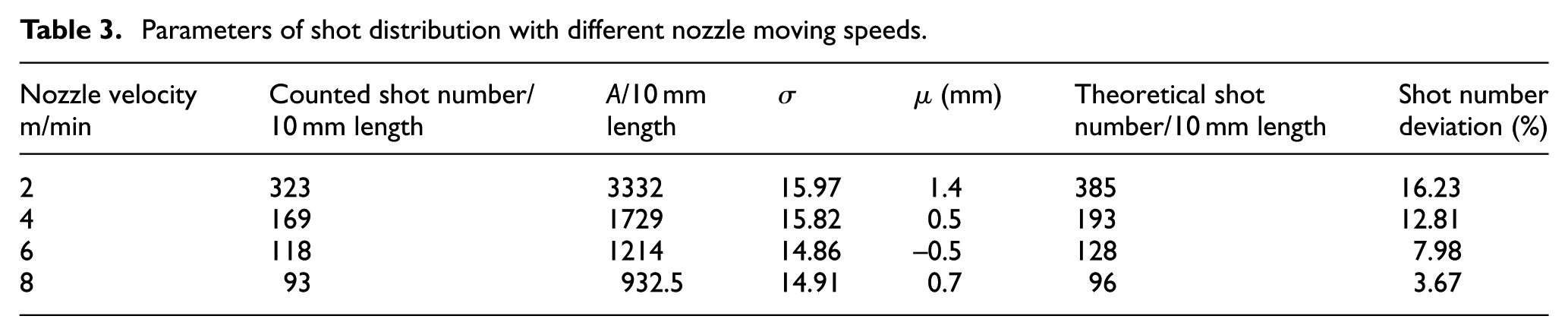
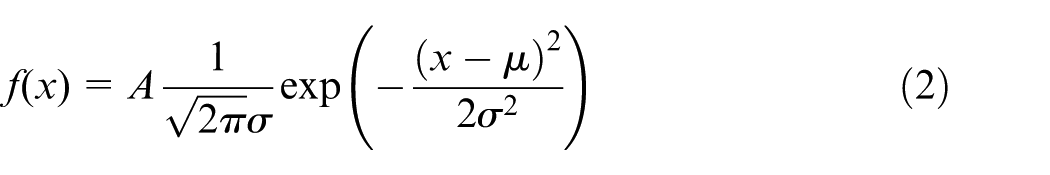
The shot dimple distributions of different peening parameters are fitted with the normal distribution function in the experiments. The values of the fitting parameters are listed in the Table 3. The standard deviation
Based on the values of the fitting parameters, the numerical shot impacting positions are obtained. Figure 12 compares the shot dimple distribution between the experiment and numerical result with nozzle moving speed of 8 m/min. In the numerical shot distributions, the values of the mean
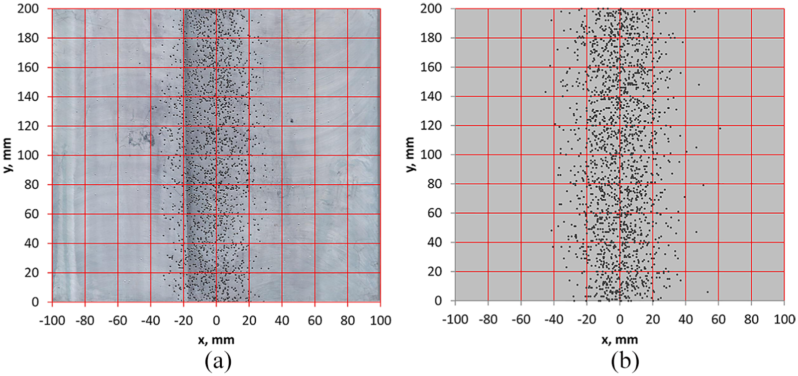
(a) Experimental and (b) numerical shot dimple distribution in one peening trajectory with peening nozzle moving speed of 8 m/min.
With the numerical shot impacting positions, the induced stresses are calculated and introduced to the section points of the shell element of the plate. Figure 13 shows the initial Mises stress distributions with relaxation ratio
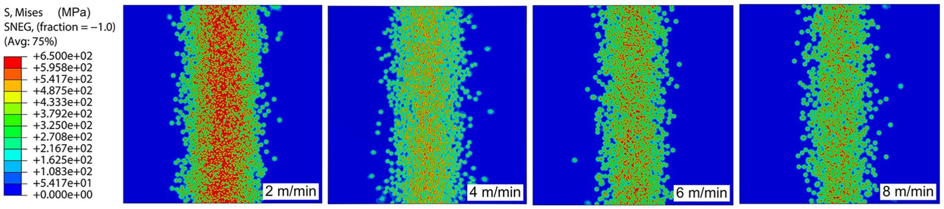
Numerical shot distributions and initial Mises stress fields with relaxation ratio
Resulting shape of simulated and experimental plate
Under different peening parameters, the resulting shapes of the plate were obtained by simulations. The peen forming shapes of the plate in experiments were scanned in three dimensions (3D). Figure 14 shows the comparison of the simulated resulting shapes with relaxation ratio
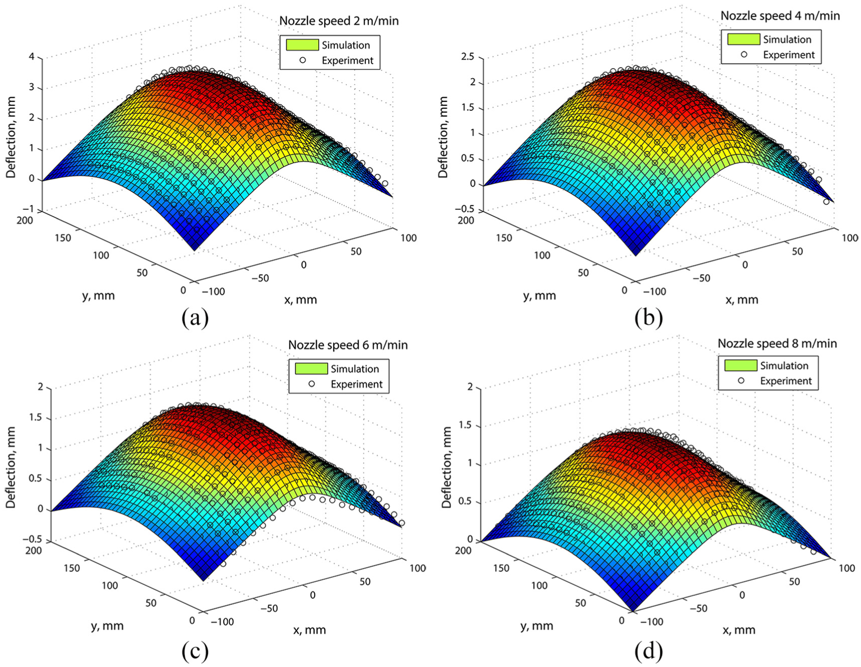
Comparison of simulated and experimental contours with nozzle moving speeds of (a) 2, (b) 4, (c) 6 and (d) 8 m/min. The relaxation ratio
The shape of the plate peened in strip region is aspheric. In the peening region, the forming curvature in the transverse direction is obviously larger than the curvature along the peening strip. In the blank region, the curvature deformations are relatively small.
Another comparison between the simulated resulting shapes with relaxation ratio
The geometry of peened plate is dependent on the impact locations and plate size. With uniform location of impacts and narrow plate, the peened plate tends to be spherical in geometry as shown in Figure 10. Peening treatment applied on local regions results in non-spherical geometry as shown in Figures 13 and 14. In addition, uniform location of impacts combined with a square plate may lead to a non-spherical geometry owing to instability of geometry deformation. 18 With the methods proposed in this article, the resultant geometry of peened plate can be determined by FE simulation with nonlinear solutions.
Computational resources
The shot peening forming deformations of a plate peened in reality can be numerically simulated with the above combined methodology. In the procedure, first, the transresidual stress field of single shot impact is calculated with the expanding cavity model. Second, the induced stress field of a large number of shot impacts is calculated by considering the overlapping of the stress fields of adjacent shot impacts. Third, the induced stress field is introduced to the FE model to obtain the resulting shape of the plate.
The first and second steps were carried out in the software Matlab 7.10. The third step was achieved in the software Abaqus 6.10. Compared with the conventional simulations of shot peen forming processes with a large number of shot impacts, such as Wang et al.’s 12 work, the computation time in FE simulation has been significantly reduced by avoiding contact detection between the shots and the target. The demand of computational resources in terms of disk space is reduced by modeling the plate with shell element instead of solid element.
The methodology proposed in this article has the merit of the finite/discrete element method 19 that the random distribution of the shot impacts is considered. In the FE simulation process, the solution of the problem is only to balance the induced stresses.
Conclusion
A methodology combining analytical methods and FE simulation was proposed to make the simulation of the shot peen forming process more realistic. The computational time and the demand of the disk space are significantly reduced by avoiding the contact detection between the surfaces of the shots and the target and by modeling the plate with shell element. The combined methodology provides a tool for shot peen forming simulation with a large number of shot impacts. The simulation can be used to predict the relationships between the shot peen forming parameters and the formed shapes, thus saving the cost of the physical experiments to establish the relationships.
Footnotes
Declaration of conflicting interests
The author(s) declared no potential conflicts of interest with respect to the research, authorship, and/or publication of this article.
Funding
The author(s) disclosed receipt of the following financial support for the research, authorship, and/or publication of this article: The authors would like to acknowledge the support for this research work from Natural Science Basic Research Plan in Shaanxi Province of China (Grant No. 2018JQ5084), Natural Science Foundation of Shaanxi Provincial Department of Education (Grant No. 18JK0571), National Natural Science Foundation of China (Grant No. 51805432) and China Postdoctoral Science Foundation (Grant No. 2018M633541).