
Abstract
Dynamic vibrations of air bearing motor spindles have significant influence on the surface quality in ultra-precision machining. In this article, the influence of the vibration caused by the unbalanced magnetic force on the diamond turning is investigated on the basis of the theoretical and experimental method. A permanent magnet motor model (10 poles and 12 slots) is built and then simulated to gain a periodic unbalanced magnetic force. The effects of unbalanced magnetic force on the inclination of the spindle shaft is analyzed, which would affect the surface quality of the workpiece, and the surface topography of the workpiece is predicted during an unbalanced magnetic force acting on air bearing motor spindle. The theoretical analysis and experimental turning results validate that the angle between the direction of unbalanced magnetic force and the feed direction has a certain relationship with the profile of the machined surface. Also, under different turning speeds and directions, the surface topography of the machined workpiece shows a 10-cycle-per-revolution pattern, which has good agreement with the simulations of periodic unbalanced magnetic force. This research work provides a theoretical foundation for the fault diagnosis of air bearing motor spindle caused by motor rotor eccentricity and its effect on surface generation in turning.
Keywords
Introduction
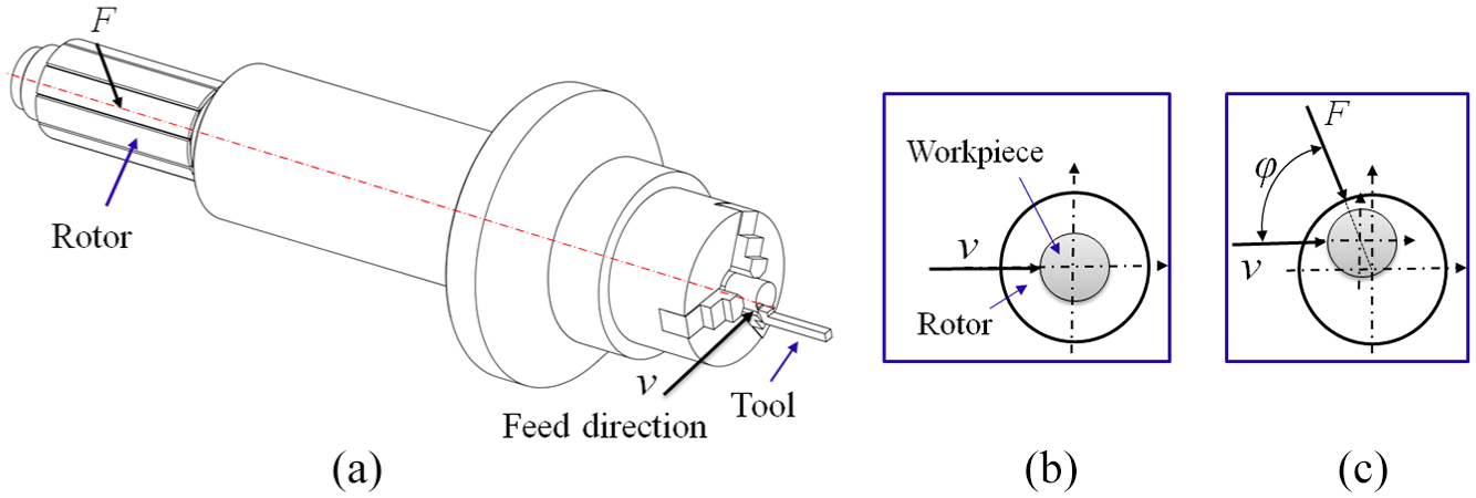
Ultra-precision diamond turning is widely used in manufacturing optical surfaces, and ultra-precision machine tools are irreplaceable to meet the strict requirements for precision machining. The overwhelming majority of ultra-precision machine tools are equipped with the air bearing motor spindle (ABMS), which is the core component of ultra-precision machine tools for achieving the desired accuracy and roughness of workpiece surface.1–3 Figure 1 illustrates the schematic diagram of an ABMS, which is supported by two axial aerostatic bearings and a journal bearing, and the spindle shaft and the motor rotor are connected directly. Because ABMS is an ultra-precision system, the manufacturing imperfections and assembly misalignments easily affect the rotation accuracy of ABMS, which introduces unwanted motion errors to the rotational spindle system such as radial, axial, or tilt Abbe offset errors.4,5 Those errors in ABMS affect the machining productivity and quality of the workpiece surface. Therefore, many scholars have studied the dynamic properties of ABMS,6–8 and they have also made many achievements in the spindle system. Indeed, there are still many problems with the spindle system, which need to be studied deeply, and these problems also play important roles in the machining performance, which obviously could reduce machining accuracy.
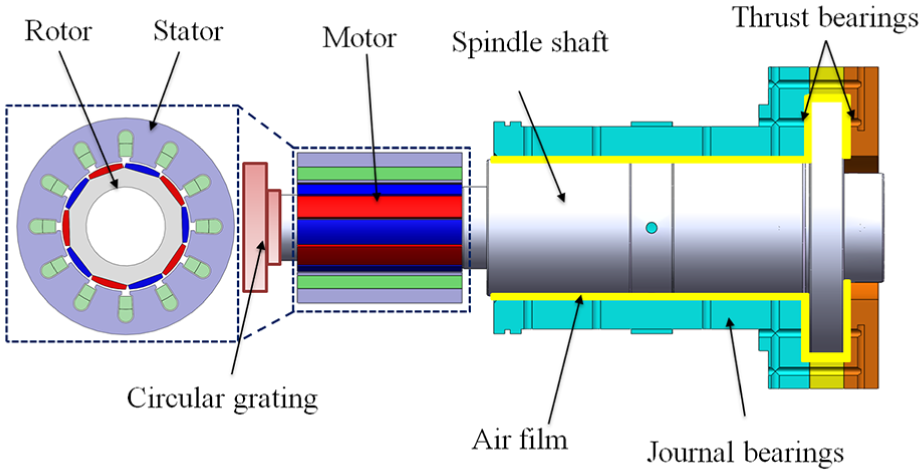
Schematic view of an ABMS.
ABMS is usually driven by a permanent magnet synchronous motor (PMSM), so the motor also has a great effect on the performance of ABMS. According to the different power supply, motors can be categorized as a DC motor or an AC motor, such as a brushless permanent magnet synchronous motor (BLPMSM) and AC brushless induction asynchronous motor (BLIAM). In addition, a motor that generates a square wave or a trapezoidal wave is a brushless direct current motor (BLDCM), and a motor that generates a sine wave is a PMSM. By changing the rotating magnetic field of the stator, the rotor in BLIAM generates the induced current and produces electromagnetic torque. The motor rotor cannot produce magnetic field directly, so the rotor rotating speed is less than the synchronous speed. Besides, compared to BLIAM, BLPMSMs have obvious advantages, such as high power density, high efficiency, high reliability, small size and better dynamic performance. 9
Ideally, the motor rotor center is concentric with the motor stator center, and the electromagnetic force acting upon the rotor surface is balanced. 10 However, due to tolerance in manufacture or assembly, the motor rotor eccentricity (MRE) between stator axis and motor rotor axis is unavoidable in practice. 11 If the motor rotor axis is misaligned with the center axis of the stator bore, the air-gap magnetic field becomes distorted, resulting in an unbalanced magnetic force (UMF). Unfortunately, UMF could degrade the motor performance and increase the vibrations and acoustic noise. As MRE increases, the values of UMF in PMSM increase linearly. To reduce magnetically induced vibrations and noise, Song et al. 12 investigated the relative amplitudes of the harmonics of UMF generated by the MRE. Han et al. 13 proposed a magnetic equivalent circuit modeling method to calculate both the radial and the tangential eccentric force of motors. To control motor vibration and improve the performance, Qiao et al. 14 proposed an active control scheme with built-in force actuator for unbalanced vibration of the flexible motorized spindle and applied an unbalance identification algorithm to control the tool vibration. Wang et al. 15 studied the frequency spectrum characteristics of electromagnetic force under different rotor eccentricities to suppress electromagnetic vibrations. Admittedly, motor experts have analyzed many working properties of motors, 16 but few studies have been carried out to analyze the motor effects of ABMS on the actual machining process. Because ABMS is the integration of a PMSM and air bearings, ABMS has the complexity of multiphysics coupling characteristics, 17 and the mechanisms of ABMS have changed considerably in comparison with the traditional electromechanical drive system.
At present, a series of researches on dynamic performance of ABMS have been discussed, both theoretically and experimentally. For example, Zhang et al. 18 built up a dynamic spindle model to describe its dynamic responses, involving translational motions and tilting motions. Liang et al. 19 designed and optimized the structure of an ultra-precision spindle for crystal machining. Chen et al.20,21 pointed to the fact that the measurement and analysis of ABMS had great significance for deeply understanding the spindle performance and improving machining quality. Hence, many new concepts of ABMS have been provided, and also new approaches have been developed for implementing ABMS.1,22,23 However, some key technical problems are still not solved. In the past, the mechanical characteristics of the spindle shaft and the electrical characteristics of the motor were separately analyzed in ABMS. Nevertheless, because the motor rotor and spindle shaft are coupled as a body, they always interact with each other, so the spindle system shows a multi-field and multi-parameter coupling relationship. 24
A common source of noise and vibrations in a PMSM is the UMF due to MRE.25,26 Motor experts study UMF which generates periodic fluctuations caused by MRE. Ma et al. 27 studied UMF when there is MRE in PMSM; investigated the influence of slot–pole combination on UMF in PMSM having different MRE and magnetizations, which shows the motors with different magnetizations have different UMF due to MRE as magnet thickness and slot–pole combination vary; and also analyzed the radial vibration forces in 10-pole/12-slot motors. 28 In addition, in order to analyze the influence of UMF on the axial vibration of the spindle system, Usman 29 analyzed the effects of a motor on the hydrostatic bearing system by installing an axial displacement ball target. The tested signals showed that the spindle shaft produced a nine-cycle-per-revolution pattern in the axial error signal, which was consistent with the motor poles when the spindle rotates at different speeds (500–3000 r/min). Meanwhile, in order to further study the effects of motor characteristics on machining surface deeply, Zhang et al. 30 discussed the dynamic characteristics of spindle imbalance-induced forced vibration and its effect on surface generation in diamond turning, which adopted a 12-pole permanent magnet motor as the driving source of an ultra-precision spindle system. Under the action of UMF on the motor rotor, the spindle vibration with a fundamental cyclic frequency of 2p per revolution (the spindle motor pole number) would occur to produce the corresponding straight radial patterns at the machined surface. Besides, previous work has done some research on MRE of a vertical ultra-precision spindle, 31 and a range of rotor eccentricities was calculated to assess the impact of UMF on the spindle performance. MRE has a significant influence on the spindle vibration indeed, which dramatically reduces the surface quality.
In the field of ultra-precision machining, the machining errors, especially geometric errors, have a significant influence on the form accuracy of machined surfaces. Lots of researches have been done on the surface roughness error or figure error in turning, 32 and a systematic review of influencing factors and theoretical modeling methods of surface roughness in turning process has been presented. 33 However, some surface topography problems of end face turning have not been studied in depth, so it is a very effective method to study the turning problem using end face prediction. Surface generation simulations can be used to design machine tools, which bridge the gap between the machine tool performance and the surface topography generation. 34 Therefore, in order to study the influence of the motor vibration problems on the turning, it is a useful method to study motor vibrations in ABMS though the surface topography simulation.
In order to study deeply the dynamic characteristics of the motor on horizontal ABMS and MRE on the diamond turning, an ABMS is used as the research object in this study, which adopts a motor (10 poles and 12 slots) as the driving source. The characteristics of UMF are presented and its effects on ABMS are discussed. Also, the finite element method (FEM) is used to analyze the MRE, and the dynamic behaviors of ABMS caused by UMF are presented. In addition, a numerical surface simulation model is established to investigate the influence of MRE on the turning workpiece surface topography. The workpiece surface, which shows a concave or convex shape for different turning directions, is further explained. Furthermore, under different turning speeds and directions, a 10-cycle-per-revolution pattern is predicted for the machined surface, on the basis of the proposed surface simulation model. Experimental turning results are conducted to validate the theoretical analysis.
UMF induced by rotor eccentricity
Maxwell stress tensor
In a PMSM, the main component of the magnetic forces acting on the motor rotor perimeter is the tangential direction force to drive the rotor rotating. Because of the manufacturing tolerances, the rotor axis is not concentric with the stator axis, and there will be an UMF acting on the motor rotor. An approach for calculation of UMF is to derive the components of the magnetic force from the magnetic field. In the air gap of PMSM, the radial and tangential delta components of force densities can be evaluated using the Maxwell stress method. As the magnets in the rotor have a much higher permeability than air, the tangential delta component of air-gap flux density is much smaller than the radial component, so the tangential delta flux density becomes negligible. Therefore, the magnetic force is generally expressed as35,36
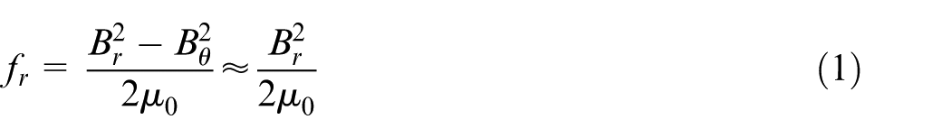
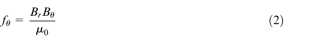
where fr denotes the radial force density; fθ denotes the tangential force density; Br and Bθ denote the radial and tangential circumferential air-gap flux density, respectively; µ0 denotes the air permeability; and θ denotes the angular position of the rotor with reference to the axis of a magnetic pole.
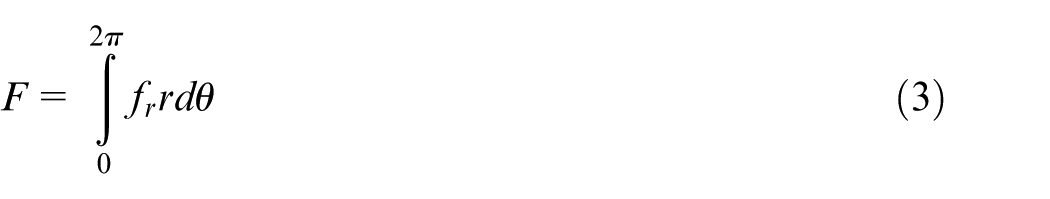
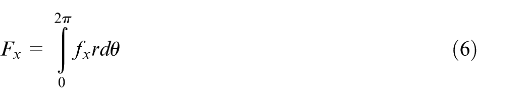
UMF acting on the motor rotor can be obtained as the integral of the radial force density along the rotor perimeter, which is expressed as
Using a Cartesian coordinate system, the radial force density is converted to the corresponding magnetic force density, which can be expressed as


Thus, UMF acting on the motor rotor can also be obtained by integrating the unbalanced magnetic tension on the corresponding rotor surface, which can be expressed as
Therefore, the total magnetic force of the motor can be calculated as
UMF under MRE
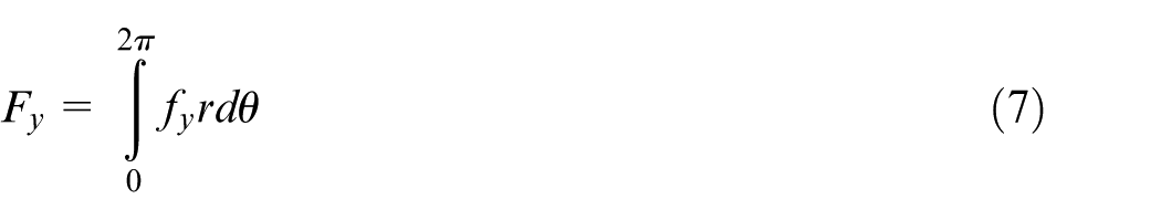
In an ideal PMSM, the rotor center is aligned with the center of the stator bore, and the rotor center of rotation is at the same position as the geometric center of the stator bore, as shown in Figure 2(a). However, in reality, the rotor center is not concentric with the stator bore, which commonly consists of two forms: static style and dynamic style. Usually, the static eccentricity and the dynamic eccentricity are simultaneously present in the motor.37,38 In the case of a static eccentricity, the air gap between the rotor and the stator is stationary, and the position of the minimum radial air-gap length is fixed in a space, which is caused by the stator core ovality or incorrect rotor position, as shown in Figure 2(b). In addition, the position of static eccentricity does not change if the rotor assembly stiffness is hard enough. A dynamic eccentricity occurs when the center of the rotor is not at the center of rotation and the minimum air gap revolves with the rotor, and the rotor rotates on the stator bore center but not on its own axis. This is a function of space and time as shown Figure 2(c). Due to the presence of MRE, the distribution of electromagnetic forces on the unit area between stator and rotor is not uniform. The static eccentricity tends to produce a steady pull in one direction, while the dynamic eccentricity creates a UMF vector rotating in synchronism with the rotor.
(a) Ideal motor (no eccentricity), (b) static eccentricity, and (c) dynamic eccentricity.
According to the Maxwell stress tensor method and FEM, the radial and the tangential magnetic traction acting on the motor rotor can be calculated. In general, the magnetic force caused by the varying air-gap electromagnetic fields can be decomposed into a delta tangential force and an UMF on the rotor. The delta tangential force is smaller than UMF, thus it is neglected here. In order to clearly describe the motor rotor and the air gap, the sizes and positions of the rotor and stator are plotted with exaggeration. The UMF F distribution is shown in Figure 3, which shows a schematic diagram of the geometry of a permanent magnet motor with MRE. In this figure, n represents the rotating speed, and points O and o represent the centers of the rotor and stator, respectively. The stator and the rotor axes are assumed to be parallel; e represents the eccentricity between points O and o; o-xy represents the coordinate system of the rotor, which uses the center o as the origin; x and y represent the lateral coordinates of the rotor center; and O-XY represents the coordinate system of the stator.
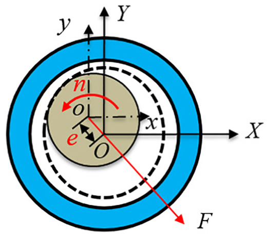
Cross section of motor with MRE.
In an ABMS, the spindle shaft is driven by an overhang motor. In this structure, there are some geometric errors between stator and rotor caused by the manufacturing or assembly process, which contains the static eccentricity and dynamic eccentricity. In addition, because a fixed clamp for the workpiece is fixed at the end of the aerostatic bearing in the machining process, the spindle system that has been balanced becomes a new imbalance system. The stator and the rotor axes are not parallel, resulting in the variation of flux path and equivalent air-gap length. As seen in Figure 4, there is a non-coincidence in the axis between the stator and the motor rotor, which is a tilting angle between the two axes. The rotor core is tilted with an angle γ on the rotor shaft leading to a non-uniform electromagnetic force over the core length, so that the UMF F produces three components: the static UMF, dynamic UMF, and inclined UMF. Moreover, the UMF can decompose in three directions, which are the radial x, y and axial z-directions. 39 In addition, the inclination angle γ is relatively small, and UMF F can be calculated according to the eccentricity between the stator and rotor, without tilt angle. The axial component force F0 can be calculated as

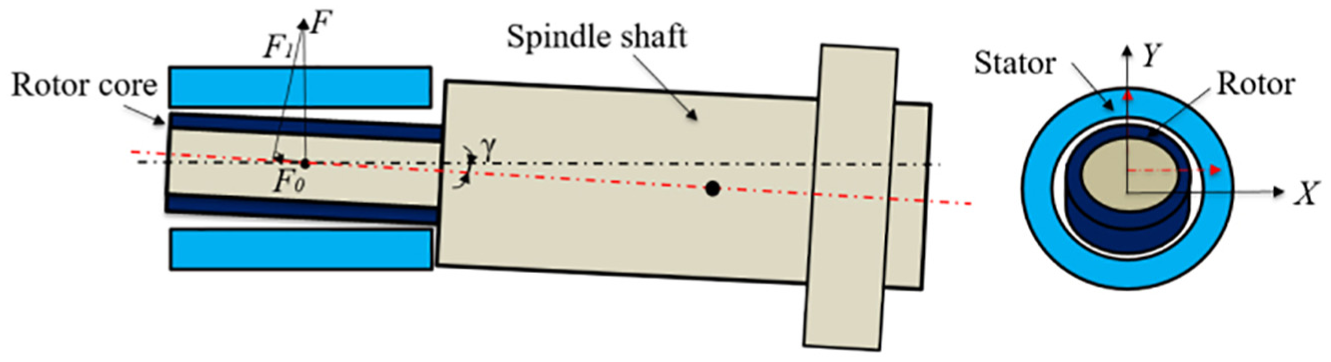
Tilt of the rotor core.
UMF calculation
UMF is difficult to calculate directly using a single analytical method. Based on the electromagnetic theory of the motor, FEM is a useful method for calculating UMF, which considers the impacts of the saturation factor and current waveform. Meanwhile, FEM can provide an accurate calculation for the dynamic motor responses when a motor is subjected to UMF. The software Ansoft Maxwell specifically emulates motor characteristics, which is a FEM based on motor design principles, so it can be used to accurately simulate the motor model. 40
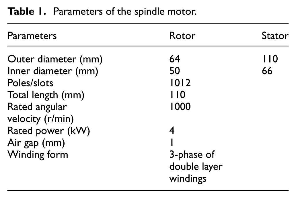
To study the effects of UMF on the motor rotor, a model of a 10/12 motor is simulated, and Table 1 lists the detailed parameters of the motor. To simplify the motor model and increase the calculation efficiency, the permeability between stator and rotor is assumed to be infinite. The rotor inner circle and the stator outer circle are selected as the boundary, which has no magnetic leakage. The motor models are simulated under no-load and load conditions, respectively, and operated at the same rated speed of 1000 r/min. At load conditions, the motor windings have a rated current of 6 A and three phases. The motor models are, respectively, simulated at no eccentricity and eccentricity (e = 5 μm, the air-gap length is set to 1 mm). In the case of load, Figure 5 shows the electromagnetic density cloud diagram of the motor in the non-eccentric and eccentric cases. In the same conditions (speed, position, and load), when the motor has no eccentricity, the maximum electromagnetic density is 1.3503 T, and the simulation of the electromagnetic cloud can be seen in Figure 5(a). When the eccentricity is set to 5 μm, the maximum electromagnetic density is 1.7045 T, which can be seen in Figure 5(b). Therefore, in the eccentric case, the electromagnetic density becomes larger, and the eccentric case is more likely to produce the magnetic saturation. Figure 6 describes UMF with no eccentricity, Figure 6(a) represents UMF with a no-load condition, and Figure 6(b) represents UMF with a load condition. It can be seen from Figure 6 that UMF values are very small, almost all less than 6 N. However, in the case of MRE, the UMF values become large. As shown in Figure 7(a) and (b), the UMF values of the motor rotor are slightly different in the cases of no-load and load conditions, having the same ripples of 10 peaks in a cycle, and the average values become greater than 40 N.
Parameters of the spindle motor.
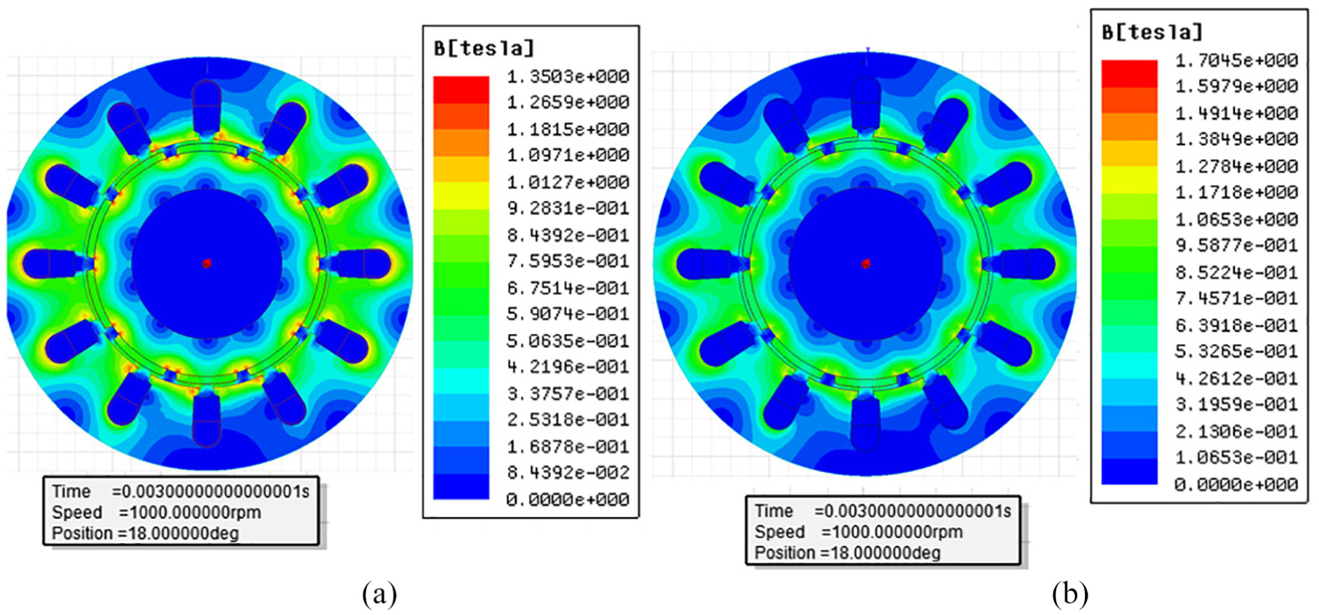
Electromagnetic cloud in the case of load: (a) no eccentricity and (b) eccentricity (e = 5 μm).
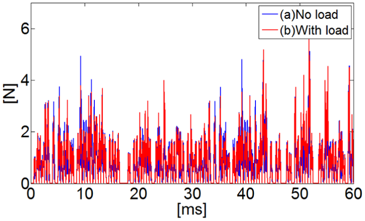
UMF curve of motor rotor (no MRE).
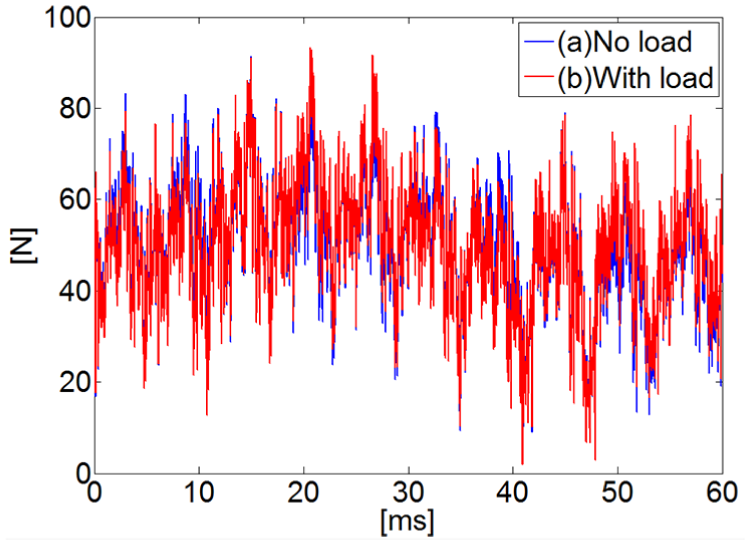
UMF curve of motor rotor (MRE, e = 5 μm).
Electromagnetic effects on ABMS in Z-axis
Turning path offset
ABMS is an ultra-precision spindle system, and the schematic diagram of the supporting form of ABMS is shown in Figure 8. Under normal conditions, the periodic UMF points to the direction of the smallest air gap, which always points to the center axis of the rotor and actually tilts the shaft in the air bearings. The dotted line of the spindle shaft in Figure 8 indicates that spindle shaft is subjected to the UMF, and the solid line structure indicates the initial position of the spindle shaft. It can be noted that the spindle periodically swings around its centroid M.
Spindle shaft tilt caused by UMF.
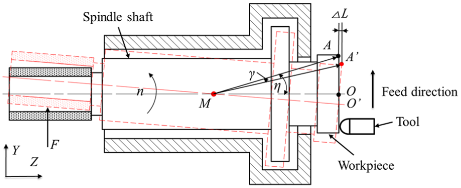
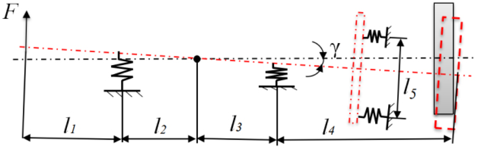
Under the action of UMF, the spindle system produces tilt, and the inclination angle between the actual position of the spindle axis and the ideal axis position is γ, which is shown in Figure 9. In this figure, l1 = 127 mm denotes a distance between the position of UMF (selecting the midpoint of the motor’s axial length) to the air inlet position of the left radial support; l2 + l3 = 130 mm denotes the distance between two rows of the radial air inlets; l4 = 225 mm denotes the distance between the positions of the right radial air inlet and the workpiece surface; and l5 = 156 mm denotes the diameter of the axial air inlets. In addition, the spindle system is designed to have a journal stiffness of 350 N/μm, and an axial stiffness of 300 N/μm. The mass of the spindle system is 28 kg, and the inertia of the spindle system moment is 0.045 kg·m2. According to the simulation of Figure 7, the stable component of UMF is assumed as F1 = 50 N, the amplitude of vibration of UMF is 15 N, and the tilting angle γ produced by the spindle is 1′, resulting in a slope of k = tan1′. As seen from Figures 8 and 9, the Z-axial displacement can be calculated using equations (10) and (11). Therefore, the amplitude ΔL on the workpiece surface is affected by the spindle tilting angle and the turning position. In addition, slope k of the workpiece surface shape caused by the inclination of the spindle axis can be expressed as equation (12)

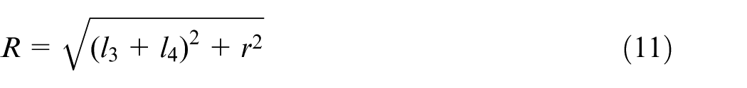

where R denotes the distance (MA) between the centroid M and the machining point A, η denotes the angle between the line (MA′) and the vertical direction, γ denotes the torsion angle formed by the line (MA) and the line (MA′), and r denotes the distance between the machining point and the workpiece center O′.
Sample tilting model of the spindle shaft.
The machining process diagram of ABMS is shown in Figure 10. The case of no eccentricity is shown in Figure 10(a), and the center projection of the workpiece and the motor rotor is in the coincidence position. However, due to the presence of UMF, the spindle is tilted, so the center projection of the workpiece and the motor rotor changes the previous position, as shown as Figure 10(b). The center of the workpiece is eccentric toward the opposite direction of UMF, where φ is the angle between the feed direction and the UMF F direction. If the angle φ is an acute angle, k is a positive value. In the opposite case, if the angle φ is an obtuse angle, k is a negative value.
(a) Turning process diagram of ABMS; (b) turning with no MRE; and (c) turning with MRE.
Simulation of surface topography
Surface quality has been recently recognized as an indispensable functional element for detecting workpieces,
41
so there is a need for an understanding of the properties resulting from surface topography. To clearly explain the effects of UMF on a workpiece surface, a surface topography model is built, which is simulated by MATLAB. Combined with the influence of UMF on the Z-axial displacement of ABMS vibration, the tool path on the workpiece surface can be taken as the research object. In the ideal case, the tool trajectory on the workpiece surface is an Archimedes spiral. Nevertheless, due to UMF, the tool trajectory will change, which reflects on the workpiece surface for the Z-direction vibration. In order to simulate the surface topography, the rotational speed of the spindle system is set to n, the feed rate of the feed system is set to f, the vibration frequency of spindle axial drift is set to
According to the above parameters, the mathematical formula of surface topography can be simulated as
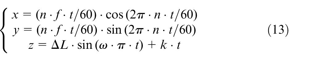
Assume that the speed rotation is set to n = 1000 r/min, the tool tip arc radius is set to R = 1.5 mm, the feed rate is set to f = 4 μm/rev, and the cutting depth is ap = 0.8 μm. According to equation (13), the coefficient k affects the profile of the machined workpiece surface. If k > 0, the workpiece surface is simulated and the result is shown in Figure 11(a), which shows a convex profile in the center. In the case of y = 0, the surface topography is intercepted to obtain the curve of Figure 11(a). The slope k of the curve is a positive number, and the curve has fluctuating traces left by the tool tip. Meanwhile, in the similar phenomenon to Figure 11(a), if k < 0, the simulation result of the workpiece surface is shown in Figure 11(b), which shows a concave profile in the center. The slope k of the curve is a negative number, and the curve also has fluctuating traces. A circle curve with a radius of 2.5 mm in the surface topography is extracted, and the extracted curve is shown in Figure 11(c); it can be seen that the simulated surface topography shows periodic ripples in the circumferential direction.
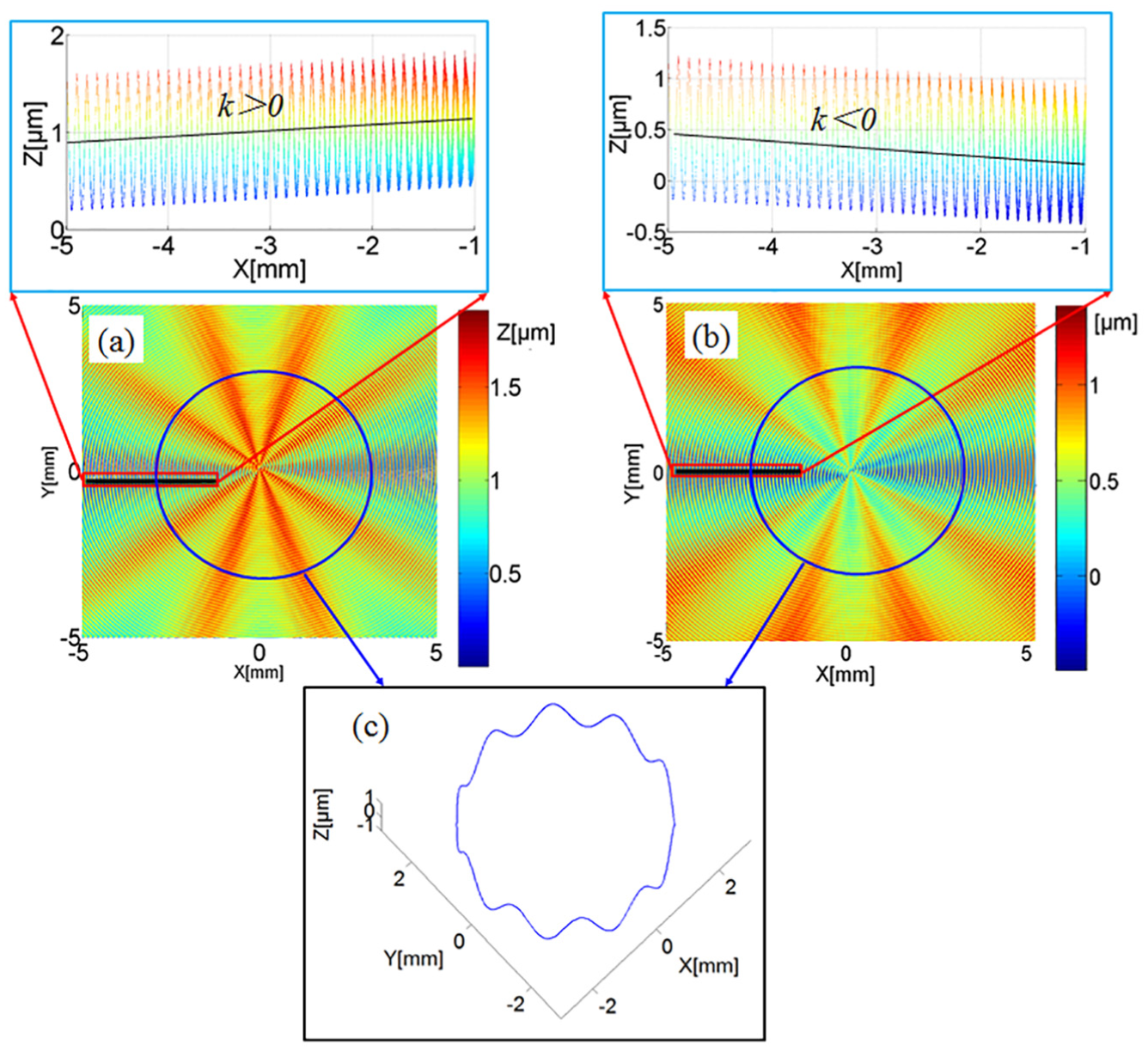
Surface topography of the simulation: (a) groove shape, (b) convex shape, (c) an extracted circle curve.
Experimental setup
In order to assess the performance of MRE on ABMS, it is necessary to carry out the corresponding experiments. Hence, a homemade ultra-precision turning machine tool is developed, which is used to obtain the ultra-precision optical components. The ultra-precision spindle of the machine tool is selected to study the UMF characteristics. The structural layout of the ultra-precision machine tool is shown in Figure 12, which shows the major components of the machine, including the ABMS and X/Z feed systems. To ensure the reliability of the experimental process, the performance parameters of the machine tool are tested, as shown in Figure 13. The straightness of the feed system is measured by a digital autocollimator called Collapex AC (AcroBeam Co., Ltd, China). The tested results show that the straightness of the X/Z feed systems is better than 0.1 μm/100 mm, respectively. An inductive micrometer of the CERTO series (measuring range = 25 mm, accuracy = 0.1 μm; Heidenhain, Germany) is used to test the stiffness of the spindle system. The spindle rotation accuracy is better than 0.08 μm. Through multiple tests, the radial stiffness of the spindle system is better than 600 N/μm and the axial stiffness is better than 450 N/μm.
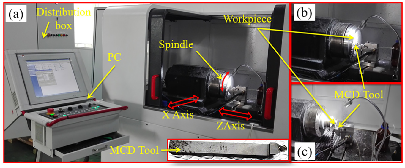
Ultra-precision machine tool and machining process: (a) structural layout, (b) workpiece fixed on a vacuum chuck, (c) workpiece fixed on a three-jaw chuck.
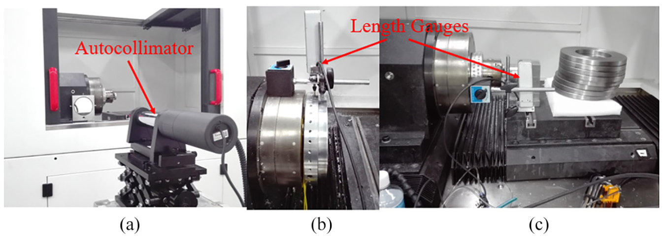
Testing of performance parameters: (a) straightness test by autocollimator; (b) stiffness test of the spindle system; and (c) stiffness of the slide.
This ABMS is installed with a 10-pole/12-slot motor as the driving power and equipped with aerostatic bearings as the spindle shaft support. The machining experiments are carried out. The material of the turning tool is monocrystal diamond (MCD), the radius of the tool nose is 1.5 mm, and the edge radius of the tool is less than 0.3 μm, which can be seen in Figure 12. In addition, the turning parameters are set as follows: the spindle speed is set of 800, 900, 1000, and 1200 r/min, respectively, and the cut depth is 8 µm. Two types of the workpiece materials are used: the smaller size of workpiece is Al 6061 and the larger size is 5A06. The experimental results of the workpiece surface are examined by a three-dimensional (3D) rough surface tester, Phase Cam 6000 (4Sight™ interferometer; 4D Technology Corporation, USA) and the laser test wavelength is 632.8 nm. The rough surface tester can detect a square range with a side length of 9 mm × 9 mm and 2 nm vertical resolution. The measurement results with only tip, tilt, and piston have been removed. Figure 14 depicts the turning process, Figure 15 describes the testing process of the workpiece surfaces, and Figure 16 shows the different directions of the spindle rotation and feed directions of the feed system for turning.
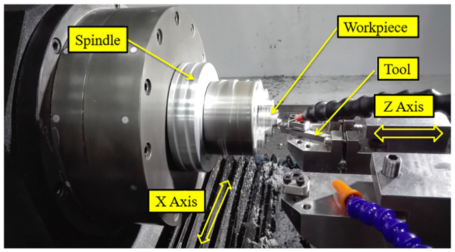
Turning the end face of a workpiece.
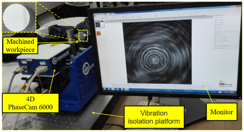
Testing the machined workpiece surface.
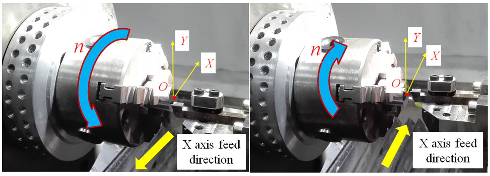
Turning in different turning directions: (a) forward turning and (b) reverse turning.
Results and discussions
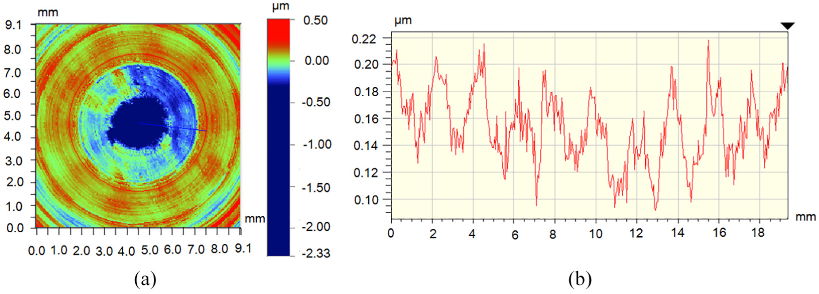
First, the turning speed of the spindle is set to n = 800 r/min and the feed speed of the X feed system is set to 10 μm/rev. The machined workpiece is tested. The surface topographies are shown in Figures 17 and 18. The surfaces have a uniform distribution of 10 periodic ripples, which can be seen in Figure 17. The surface quality of the workpiece is linearly detected, and a line is drawn from the extension to the center on the test surface topography. The position of the detected line segment is shown in Figure 18(a), and the detection result of the line segment is shown in Figure 18(b). From the tested results, it can be seen that the curve value from edge to center is almost linearly reduced, the slope of the line segment is negative, and a concave profile is shown in the workpiece center.
Tested result of a circle on the machined surface (n = 800 r/min): (a) position of an extracted circle curve, (b) value change of the curve.
Tested result of a line segment on the machined surface (n = 800 r/min): (a) position of a line, (b) value change of the curve.
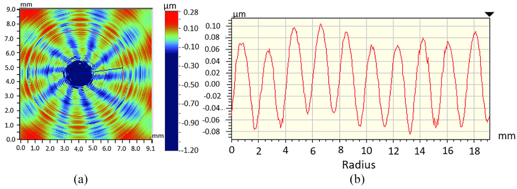
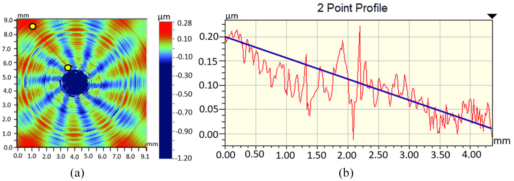
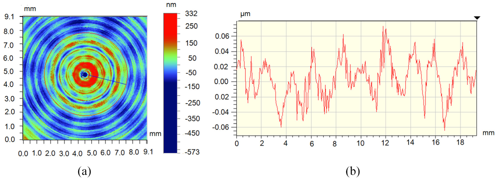
The turning speed is set to n = 1000 r/min, and the feed speed of the X feed system is set to 4 μm/rev; the turning process is shown in Figure 16(a), which adopts forward turning. The tested surface topographies are shown in Figures 19 and 20. The workpiece surfaces also have a uniform distribution of 10 periodic ripples. The surface quality of the workpiece is linearly detected for Figure 19(a). A line is drawn from the extension to the center on the test surface topography. The detected line segment is shown in Figure 20(a), and the detection result of the line segment is shown in Figure 20(b). It can be seen that the curve value from edge to center is also linearly reduced, the slope of the line segment is also negative, and a concave profile is shown in the workpiece center, which is similar to Figure 18.
Tested result of a circle on the machined surface under forward turning (n = 1000 r/min): (a) position of an extracted circle curve, (b) value change of the curve.
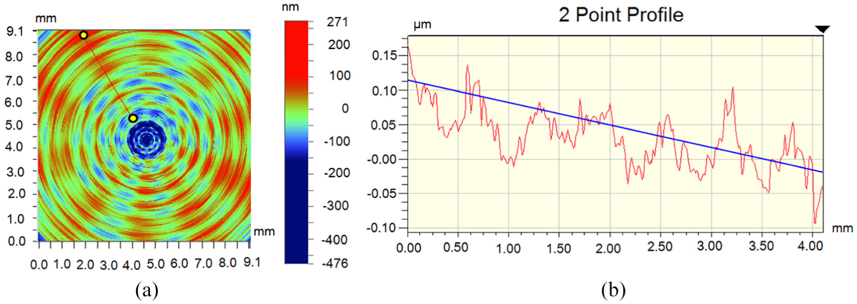
Tested result of a line segment s on the machined surface under forward turning (n = 1000 r/min): (a) position of a line, (b) value change of the curve.
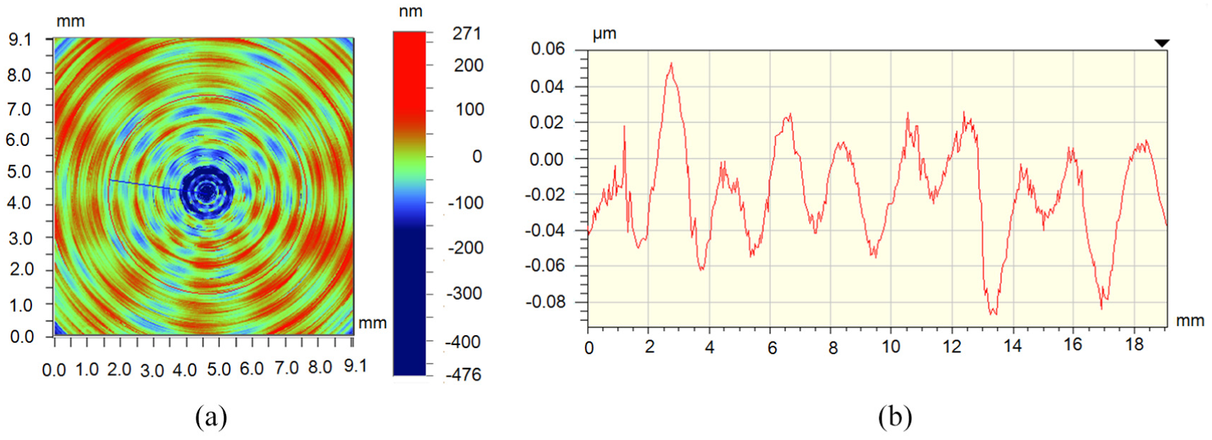
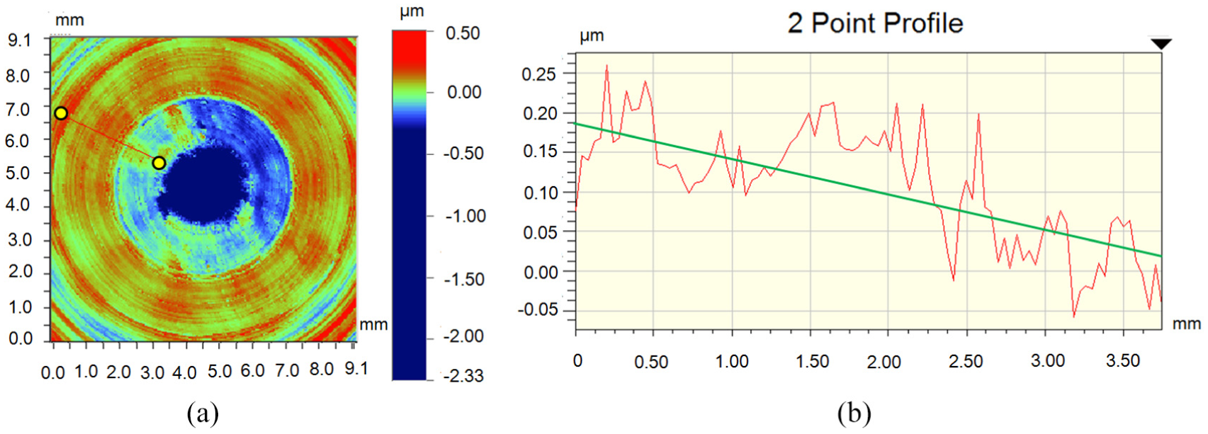
The turning rotation speed is set to 1000 r/min, and set to the reverse rotation. The workpiece is machined from the opposite feed direction. The turning process is shown in Figure 16(b). In order to eliminate some external interference, the same workpiece surface is machined, reciprocating machining many times. The machined results are shown in Figure 21. It can be seen from Figure 21(b) that the surface quality is poor and the workpiece surface topography has also the same number of periodical ripples (10). A line is also drawn from the extension to the center on the tested surface topography. The detected line segment is shown in Figure 22(a). Figure 22(b) shows the detection result of the line segment, and it can be seen that the detected value from edge to center almost increases linearly. The slope of the line segment is positive and the workpiece center has a convex shape, which is different to Figures 18 and 20. In order to further verify the circumferential vibration frequency of the workpiece surface irrelevant with the turning rotation speed, another rotation speed is set to n = 900 r/min, the feed rate is f = 9 μm/rev, and the experimental result is shown in Figure 23. There are also 10 cycles of circumferential ripples in Figure 23. Compared to the tested results, the circumferential vibration frequency of the star pattern in the workpiece surface is the same value with different speeds, which has 10 cycle ripples in the circumferential direction.
Tested result of a circle on the machined surface under reverse turning (n = 1000 r/min): (a) position of an extracted circle curve, (b) value change of the curve.
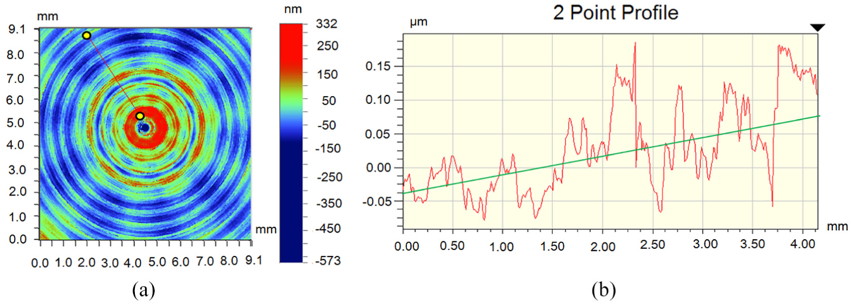
Tested result of a line segment on the machined surface under forward turning (n = 1000 r/min): (a) position of a line, (b) value change of the curve.
Tested result of a line segment on the machined surface (n = 900 r/min): (a) position of an extracted circle curve, (b) value change of the curve.
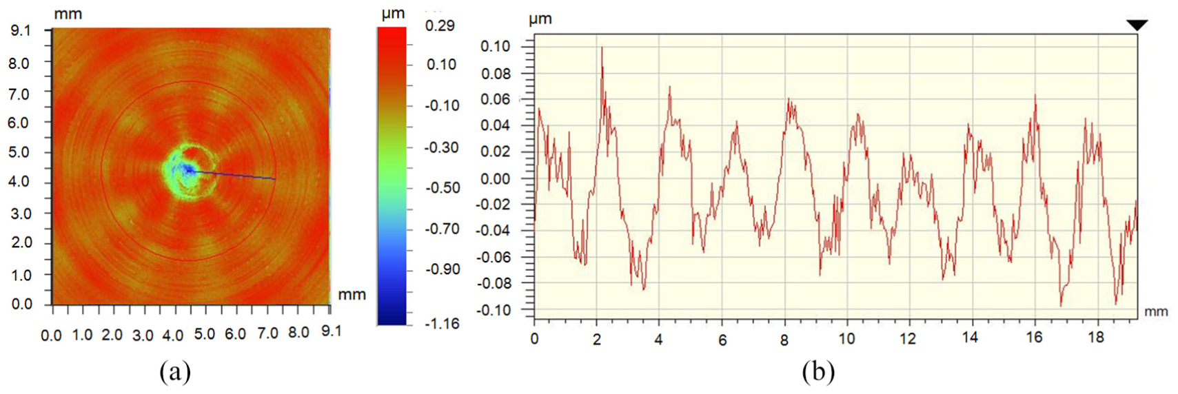
To eliminate the influence of the three-jaw chuck on the surface topography, another machining experiment using a vacuum chuck to fix the workpiece (5A06) is carried out. The turning speed is set 1200 r/min, the feed speed is 10 μm/ rev, and other parameters are unchanged. The turning process and machined workpiece are shown in Figure 24, and the tested results of the machined surface are shown in Figures 25 and 26. It can be seen from the figure that there are 10 ripples on the surface topography, which can effectively eliminate the influence of the three-jaw chuck on the workpiece. Compared to machined workpiece surfaces, the machined surfaces have the same profile under different speeds, that is, cyclical ripple. Although the amplitude values are different, the vibration frequency is more consistent. It can be noted that the vibration cycle is derived from the spindle system, and the vibration frequency is independent of the spindle speed.
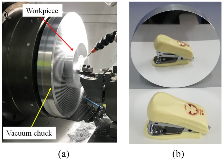
Tested result of the machined surface (n = 1200 r/min): (a) turning process fixed on a vacuum chuck; (b) machined workpiece.
Tested result of a circle on the machined surface (n = 1200 r/min): (a) position of an extracted circle curve, (b) value change of the curve.
Tested result of a line segment on the machined surface under forward turning (n = 1200 r/min): (a) position of a line, (b) value change of the curve.
After the above analysis, although there are some different amplitudes of the surface topography between the experimental results and the simulation results, which are related to other external disturbances such as spindle misalignment and motor axial offset. The overall changing trends of the surface topography are similar to the simulation, which is also a guide line on how to check for motor imperfection. Therefore, to gain the high quality of the workpiece surface, the influence of UMF should be considered before designing and installation of the spindle system.
Conclusion
A theoretical prediction and experimental verification for researching the periodic UMF in an ABMS is presented in this article. The dynamic characteristics of the UMF on ABMS and its effects on machining have been discussed in detail. It has been shown that the UMF affects surface topography. Based on the analysis and experimental results, the following conclusions can be summarized:
A 10/12 (10 poles and 12 slots) motor with MRE is analyzed at unload and load conditions, respectively. It is verified that the number of poles and slots has an influence on the periodic fluctuation of UMF. Meanwhile, the periodic fluctuation of the spindle caused by UMF changes the turning depth in the Z-direction.
The MRE has significant influence on the surface generation. A 10-cycle-per-revolution pattern has been found in the machined surface, which is consistent with the vibrations of UMF.
The prediction of the forming profile generation in end face turning is achieved on the basis of the proposed model. It is found that the angle between the direction of the UMF and the feed direction has a certain relationship to the workpiece surface shape, which can effectively predict the eccentric direction of the motor.
Footnotes
Appendix 1
Declaration of conflicting interests
The author(s) declared no potential conflicts of interest with respect to the research, authorship, and/or publication of this article.
Funding
The author(s) disclosed receipt of the following financial support for the research, authorship, and/or publication of this article: This study was financially supported by the International Science & Technology Cooperation Program of China (No. 2015DFA70630), the National Natural Science Foundation of China (Grant Nos. 51505107 and 51705462), Zhejiang Provincial Natural Science Foundation of China (LQ16E050012), and China Scholarship Council (CSC).