
Abstract
Current research is an attempt to choose suitable pin-profile for friction stir welding of aviation-grade aluminum alloy (AA6082). Six tool pin-geometries (T1–T6), that is, threaded cylindrical, taper cylindrical, four slotted, square, triangular and inverted tapered with two flat faces are used to fabricate joints. Mechanical and metallurgical properties of the joints are assessed and allied with nugget zone grain size and thermal properties. The swept volume ratio and pulsating-stirring action of pin-profiles are also quantified. It is observed that square pin-profile provides joint with superior mechanical and metallurgical properties owing to higher pulsating-stirring action and sufficient swept volume ratio. The maximum tensile strength of 300 MPa is obtained by employing square pin-profile tool. Beside this, electron backscatter diffraction analysis has been conducted to critically examine the effect of pin-profiles on grains distribution of nugget zone of friction stir–welded joints. The minimum grain size of 5.48 μm is obtained using square pin-profile.
Keywords
Introduction
In today’s scenario, ferrous metals are increasingly replaced by non-ferrous alloys especially aluminum alloys in case of structural applications. 1 However, the fusion welding of aluminum experiences problems such as oxide removal, porosity, distortion, poor solidification, shrinkage and mismatching of the composition of filler metal.2–4 These difficulties can be addressed by employing friction stir welding (FSW) technique. Figure 1 shows the process principle of the FSW technique. It is a permanent-type solid-state joining process, in which a continuously rotated cylindrical shouldered non-consumable tool with a pin is used to join two faying surfaces. The relative motion between workpiece and pin, known as mechanical stirring, generates frictional heat to produce plasticized region at the adjacent faces. This plasticized region solidifies and joining occurs. 5 This process can be used for joining similar or dissimilar materials (e.g. metal-metal, plastic-plastic, and aluminum-copper). It is available in literature that the process parameters, that is, rotational speed, feed rate, axial force, dwell time and tilt angle strongly influence the mechanical and metallurgical properties of the FSW joint. 6 In addition, FSW tool plays crucial role for obtaining sound weld. Especially, pin-profile is responsible for plastic deformation and mixing of materials.7–10 The research on FSW is mostly focused on the variation of process parameters, and their effects on mechanical and metallurgical properties of the joint; limited research has been highlighted on the effect of tool design. On the other hand, in case of aluminum 6xxx series, researchers generally focused on FSW of AA6061 and AA6063 alloy. However, in present scenario, AA6061 and AA6063 are replaced by AA6082 owing to its better properties. This study discusses the effect of pin-profiles (threaded cylindrical (T1), tapered cylindrical (T2), square (T4) and triangular (T5)) on thermal, mechanical and metallurgical properties of FSW AA6082 joints. In addition, effect of two indigenously developed pin-profiles (four slotted cylindrical (T3) and inverted tapered with two flat faces (T6)) has been explored. These two pin-profiles are developed to provide pulsating-stirring action to the cylindrical tool for adequate material flow and re-entrant feature. Moreover, electron backscatter diffraction (EBSD) analysis is employed for determining the grain size of the nugget zone (NZ) in an FSW joint.
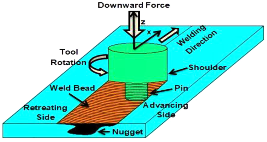
Process principle of FSW.
Experimental setup and procedure
Workpiece and tool fabrication
In this investigation, 6.35-mm thick AA6082-T6 rolled plates are used for experimentation. The material obtained in the form of sheet with dimension 300 × 300 × 6.35 mm is used. These sheets are cut into required size of 100 × 75 × 6.35 mm on a horizontal milling machine. The energy-dispersive X-ray (EDX) analysis is carried out to visualize the different phases present in the material as shown in Figure 2. Then, the faying surfaces of each plate are machined on a vertical milling machine to avoid the mismatching of plate surfaces during welding. A vertical milling machine is modified by fabricating fixture and tool for friction stir welding. Six different tool-pin geometries are design for fabricating the joint, that is, threaded cylindrical (T1), taper (T2), four slotted (T3), square (T4), triangular (T5) and inverted tapered with two flat faces (T6). The tool material is H13 with HRC 54-56. The shoulder of each tool is kept 20 mm in diameter with concavity of 8° at the bottom surface. The pin length of each tool is 6.1 mm. The schematic diagram and photographs of tool pin geometries are depicted in Figure 3.
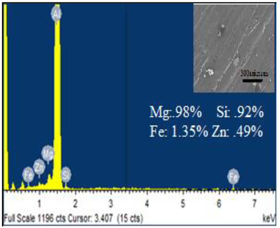
EDX analysis of AA6082.
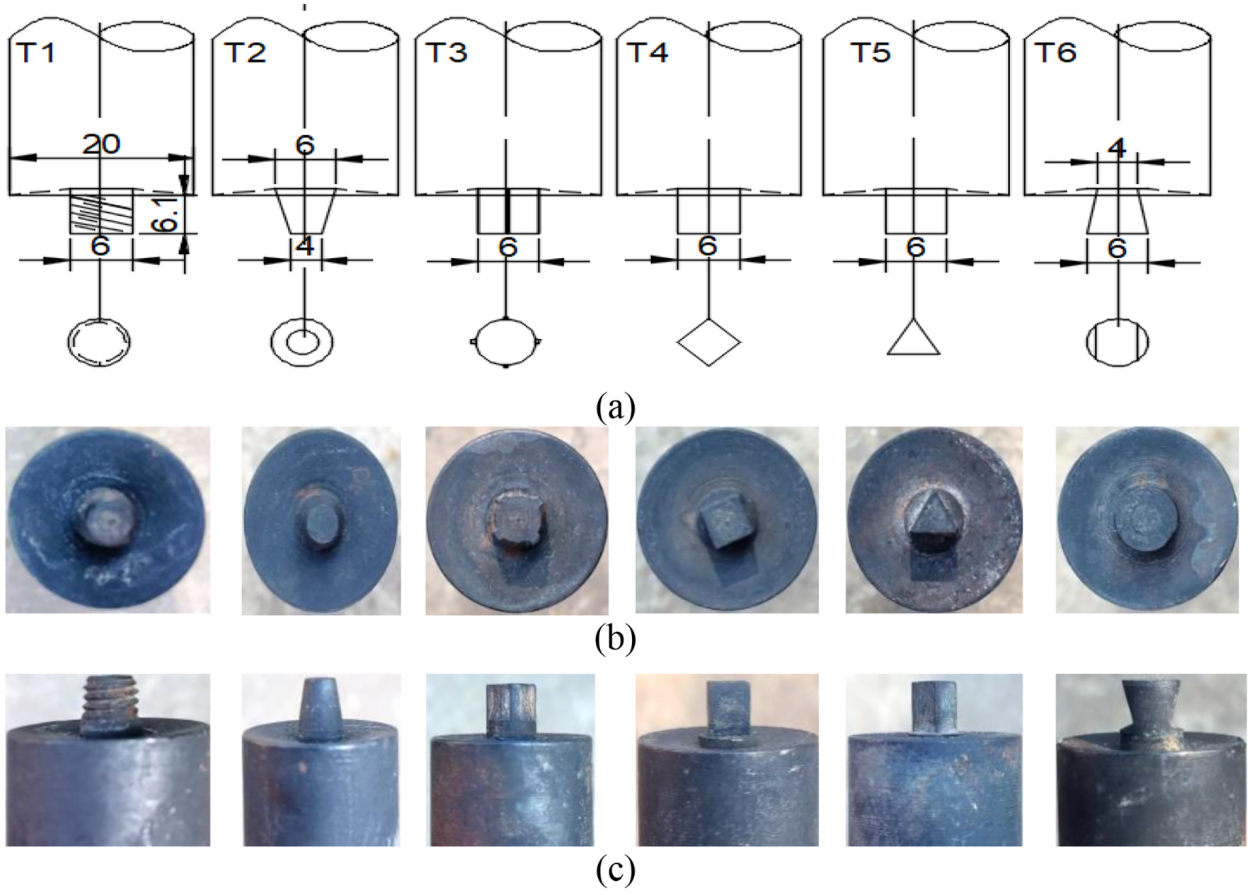
(a) Schematic diagram of tool pin-profiles (dimensions are in mm); (b) top view and (c) side view of fabricated tools.
Experimentation
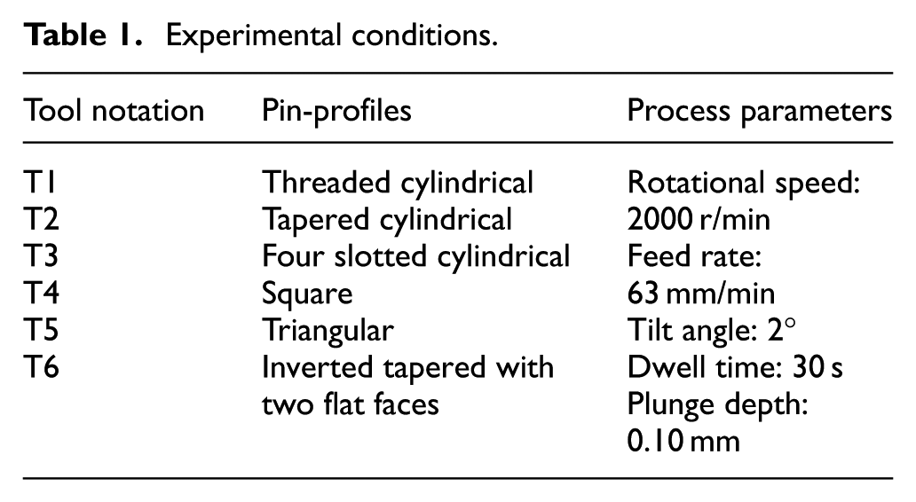
Experiments are conducted on vertical milling machine (Bharat Fritz Werner Ltd., Bangalore, India) by developing special fixture and tools. Joints are fabricated at 2000 r/min rotational speed, 63 mm/min feed rate, 2° tilt angle, 30 s dwell time and 0.10 mm plunge depth with varying pin-profiles. This welding condition (illustrated in Table 1) is selected as per literature. 11
Experimental conditions.
Test procedures
Tensile specimens are prepared as per ASTM E8M-04. Initially, the rectangular strips (150 × 12 × 6.35 mm) are formed from welded plates using power hacksaw. After that, end-mill cutter is used to modify these strips into tensile specimens. The detailed dimension of specimens is illustrated in Figure 4(a). Figure 4(b) depicts the photographic view of developed tensile specimen. Tensile testing has been conducted in UTM (Bangalore Integrated System Solutions) for evaluating the tensile properties.
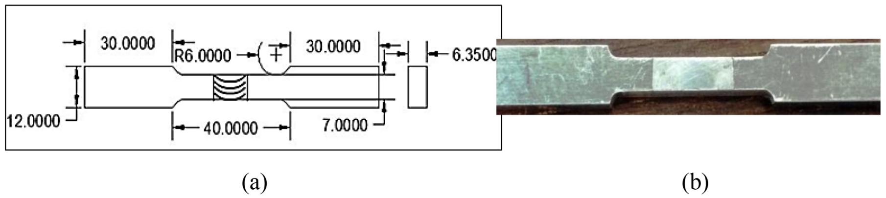
(a) Schematic diagram tensile specimen and (b) photographic view of tensile specimen.
The specimens for microhardness testing are cut into rectangular strips (22 × 6 × 6.35 mm) from welded plates from the center line. After that, emery papers of 400, 600, 800, 1000, 1200, 1500 and 2000 grit size are employed for maintaining uniformity in top and bottom surfaces of specimens to avoid error during measurement. Subsequently, cloth polishing is tried for making more reflective and scratch-free surface. Finally, these samples are analyzed by Vickers microhardness at 100-g load. The sample preparation for metallurgical analysis is same as of microhardness (Jinan XHVT Microhardness Tester). After cloth-polishing, samples are chemically etched with Keller’s reagent. Then, the samples are analyzed at macroscopic and microscopic level using optical microscope (Conation Technologies) and SEM (JEOL Ltd, NIT Kurukshetra), respectively. Optical microscope is employed to visualize the different welding zones. Finally, the samples are analyzed by SEM with EBSD attachment for measuring grain size in the NZ. Fractography analysis has been executed using SEM to study the fracture surfaces.
Temperature measurement
Eight thermocouples of K type are used for measuring the temperature at different locations on both sides (advancing side (AS) and retreating side (RS)) individually. These thermocouples are connected with an instrument named as UNILOG (Process Precision Instruments) for data acquisition. It consists of two units one is used for data recording on excel sheet named universal process data recorder and second is used for transferring the data from thermocouples to data recorder named as channel interface module. Four thermocouples are placed on the RS at a distance of 14.5 mm, 24.5 mm, 34.5 mm and 44.5 mm from the centerline and four on the AS at the same distances. The layout of thermocouples, process data recorder, and channel interface module are depicted in Figure 5. Thermocouples used in this study are L shaped with tip-diameter of 3 mm. Therefore, a hole of 3 mm diameter is drilled into the workpiece plates for inserting the thermocouples. The hole is drilled up to 5 mm in depth because the thickness of plates is 6.35 mm to prevent the contact between thermocouple tip and base plate. First two thermocouples on both sides are put at a distance of 14.5 mm from the centerline for preventing the crushing of thermocouples during the process.
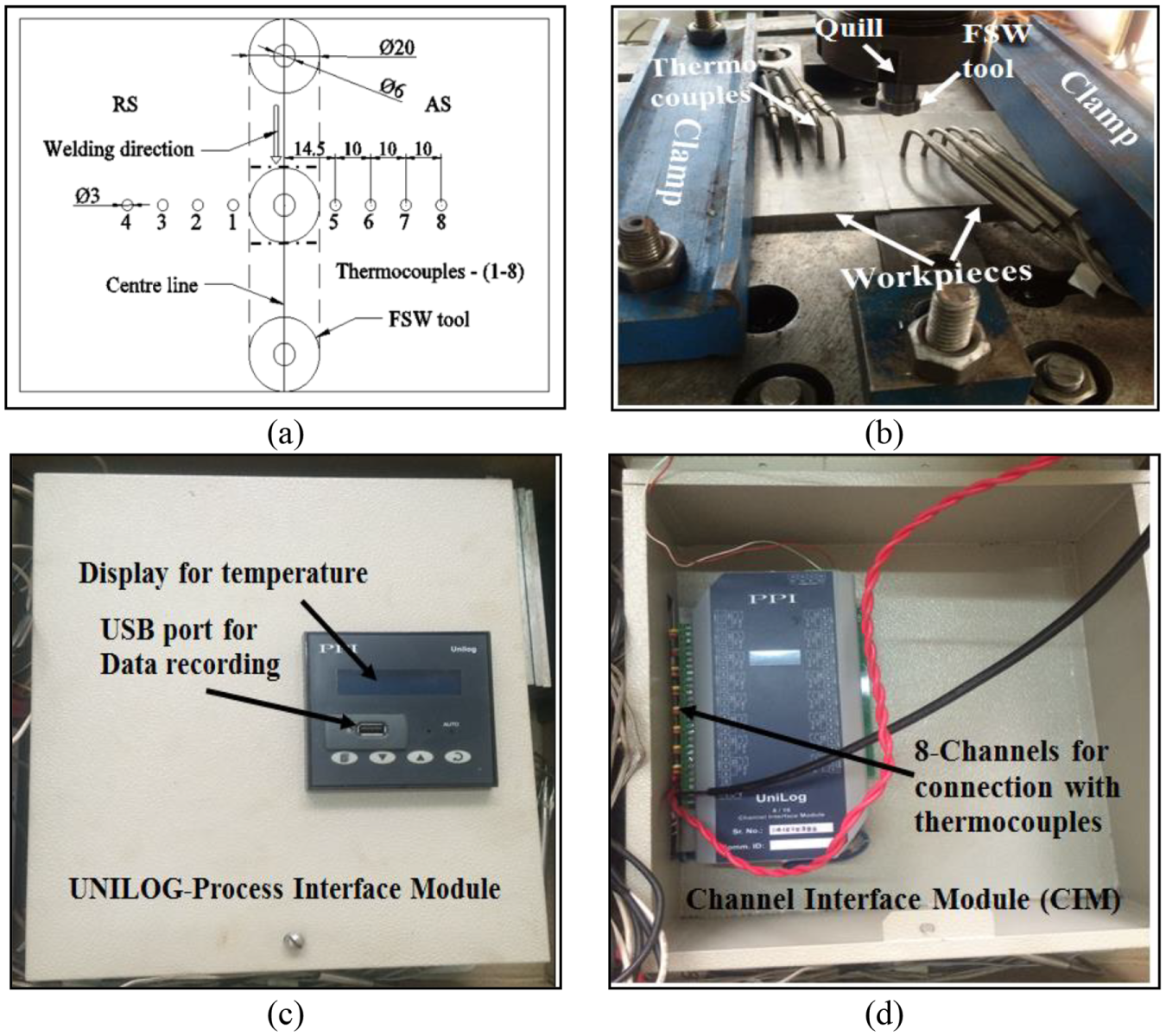
The layout of thermocouples, process data recorder, and channel interface module: a) schematic diagram of thermocouple location; b) pictorial view of thermocouple arrangements; c) process data recorder and d) channel interface module.
Swept volume ratio and pulsating-stirring action calculation
Generally, pin-profiles are associated with eccentricity for the FSW process except for cylindrical pin. The peculiarity of pin geometry controls the movement of incompressible material flow. It results in flow of plasticized material about the pin geometry. This eccentricity of the rotating body is also associated with the dynamic orbit. 12 Each pin-profile has its dynamic orbit for the FSW process. The path for incompressible material flow from leading edge to trailing edge is decided by the correlation between dynamic volume (volume swept by pin during rotation) and static volume (volume of pin itself). The swept volume ratio is calculated as per Equation 1. Table 2 represents the dynamic area, static area and swept volume ratio for different pin geometries

Dynamic area, static area, swept volume ratio and pulsating-stirring action for different pin-profiles. 13
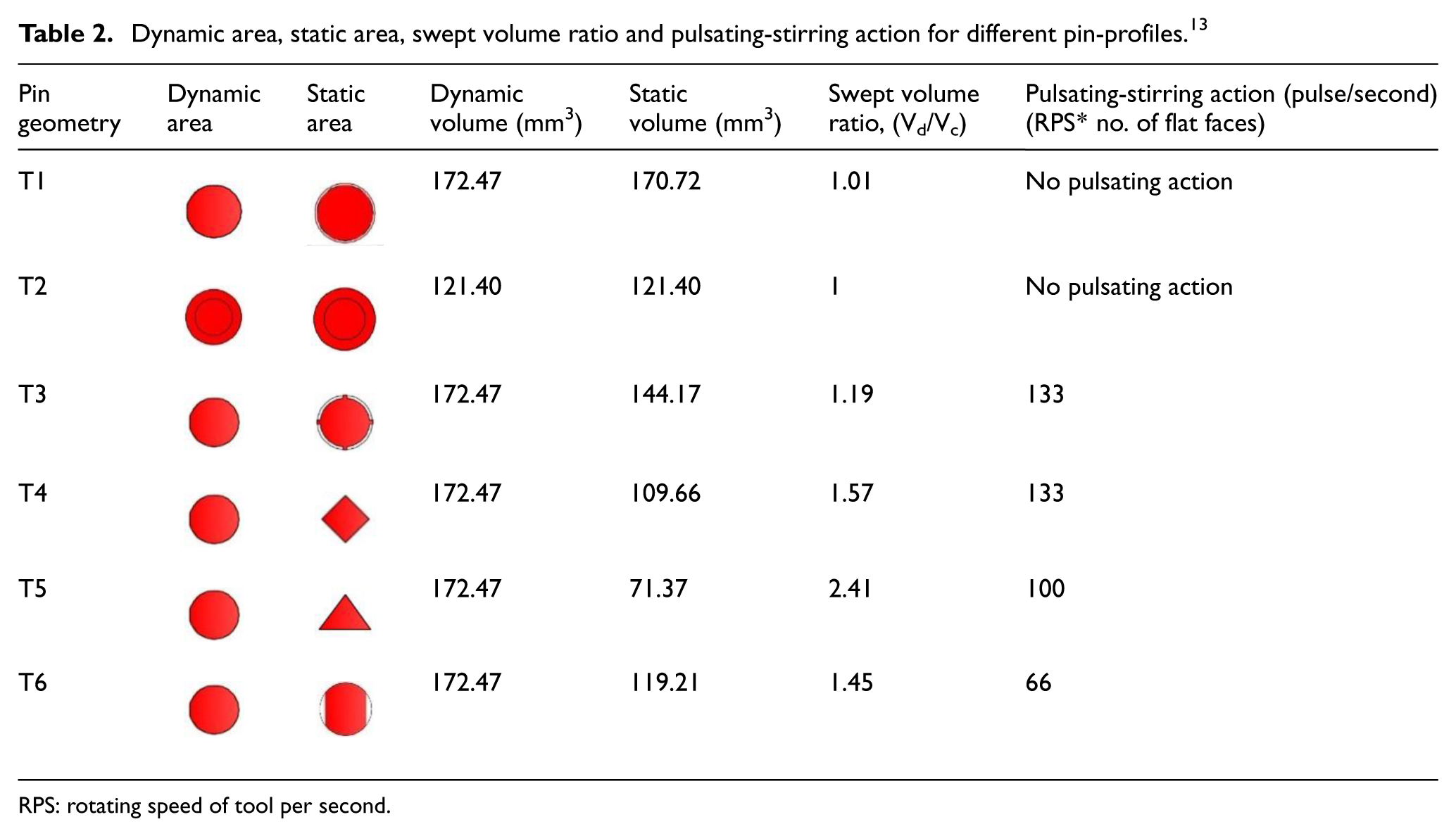
RPS: rotating speed of tool per second.
During the FSW process, the rotating tool generally remains in continual contact of the material when the tool is cylindrical or conical in nature. If tool is having flat faces (e.g. square pin, triangular pin and four-slotted pin), during each revolution, tool’s flat faces strike the material and produce a pulsating-stirring effect. The pulsating-stirring action significantly influences the material flow during the process. 14 In this study, six different types of tool profile are employed. Among them, in case of cylindrical and tapered, no pulsating-stirring action can be observed. However, in case of four other pin-profiles, this effect can be encountered. The pulsating-stirring action of the pin-profile can be calculated by multiplying the number of flat faces with rotating speed of tool per second (RPS × no. of flat faces). Table 2 depicts the pulsating-stirring action of different pin-profiles.
Result and discussion
Thermal analysis
The effect of pin geometries on thermal cycle of the FSW process is illustrated in Figure 6. It is observed that the temperature increases significantly with the passage of time during the process. The peak temperature on the AS and RS for different pin-profiles is depicted in Figure 7. It is observed from Figure 7 that AS temperature is higher than RS temperature. It confirms non-symmetrical heat generation during the process. This is happened owing to movement of material from the AS to RS by rotating the pin. During the movement of material from the AS to RS, the solid material transforms into semi solid; thus, this semi solid material cools on the RS. Therefore, AS has higher temperature than RS. A maximum temperature is obtained on the AS, that is, 306°C at a distance of 14.5 mm from the centerline by tool T1. In addition, the highest temperatures obtained by tool T4 is minimum on both sides, that is, 251°C on the AS and 241°C on the RS. The maximum peak temperature at both sides by tool T1 is 306°C on the AS and 283°C on the RS, respectively. It shows that T1 tool produces higher heat input at identical experimental condition than the other tool pin-profiles. The friction between the tool and workpiece generates heat, which causes shearing and extrusion of metal.15,16 The upper surface of the plates are experienced more frictional and stirring action than the lower surface of the plates. This is happened because the upper surface is contact with the tool shoulder surface and lower surface is contact with pin surface, which results in higher pressure on the upper surface than the lower surface. The loss of heat during the process is due to thermal conduction and convection. The conduction takes place between the backing plate and lower surface of the workpiece, and convection takes place between top surface of the workpiece and the atmosphere. It is understood that the pin-profile has a considerable effect on heat generated during the process. The pin geometry plays a crucial role in material movement and plastic deformation during FSW.17–19 Each fabricated tool pin-profiles except T1 and T2 produces eccentricity, that is, expressed in the form swept volume ratio as shown in Table 2. The presence of eccentricity during the process improves the material flowability and provides the pulsating action, which resulted in additional friction heat. Moreover, in case of tool T4 and T5 interfacial area of contact of the pin with the workpiece is less than the tool T3 and T6, which results in decrement of heat generation as shown in Figure 6.12,20 In case of tool T2, due to the conical shape of the pin, it offers an additional downward force to plastic material that resulted in improvement in the flowability of bottom metal. In contrast, four-slotted pin (T3) has the highest surface velocity at the pin edge, which produces stronger stirring action; hence, it has an improved metal flow under the pin.4,21
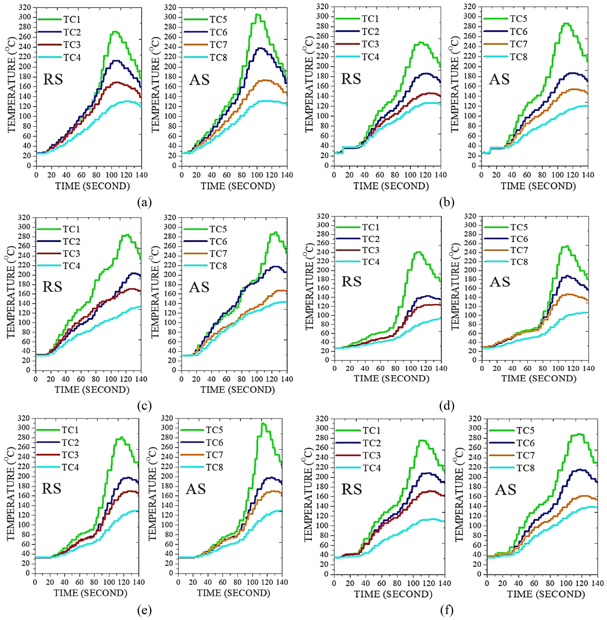
Heat distribution during FSW process using different pin-profiles: (a) threaded cylindrical; (b) tapered cylindrical; (c) four slotted cylindrical; (d) squared; (e) triangular and (f) inverted tapered with two flat faces.
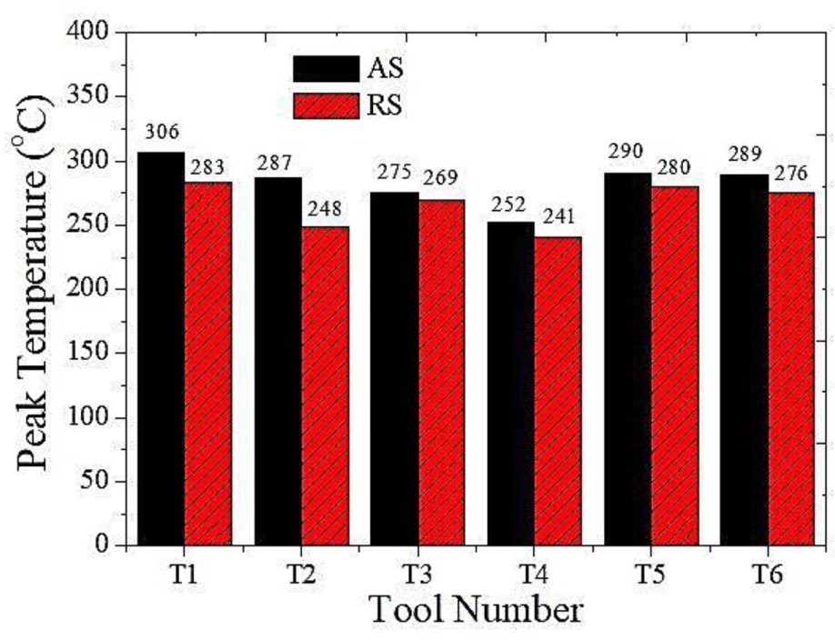
Peak temperature on the advancing and retreating sides for different pin-profiles.
Tensile properties
Table 3 reveals the tensile properties of the base metal (BM) and joint fabricated using different pin-profiles. It is clear from the Figure 8 that tensile properties of the fabricated joints are less than that of the BM. This is owing to the dynamic recrystallization of the NZ that results in the dissolution of strengthening precipitates. 1 Furthermore, thermal cycles, swept volume ratio, pulsating-stirring action and grain size affect the tensile properties of the joints.16,22 The pin geometry plays critical role in heat generation and material flow during the process. In FSW, material is extruded from the AS and forged at the RS during transverse movement of the tool. 23 The main concern of tool pin-profile is to stir the material in the NZ and move it from front to back to produce sound welds. The swept volume ratio is observed in non-cylindrical pin-profiles. These pin-profiles are associated with eccentricity during the FSW process that causes swept volume ratio more than one. This swept volume ratio provides a path for plasticized material to flow from the AS to the RS. In addition, these profiles also allow hydro-mechanically incompressible plasticized material flow more easily nearby the pin than other profiles. 14 On the other hand, pin-profiles with flat faces are allied with pulsating-stirring action. This characteristic of pin-profiles also increases mixing of material in the NZ to produced sound weld. In this research work, it is observed that a joint fabricated by square pin-profile produces superior tensile properties. Whereas, threaded and conical pin-profile fabricated joint possesses minimum tensile properties. It is observed that swept volume ratio is one for conical profile and nearly one for threaded pin-profiles. Moreover, these profiles have no pulsating-stirring action. Owing to this, tensile properties of the joints fabricated by these pin-profiles are less than other pin-profiles. In addition, threaded pin-profile generates higher heat input that resulting in dissolution of strengthening precipitates. Conversely, four slotted, square, triangular and inverted taper with two flat faces profiles are associated with swept volume ratio greater than one and pulsating-stirring action. In the case of four-slotted pin, swept volume ratio is 1.19, which is not much higher than the threaded cylindrical and conical pin-profiles. Moreover, it has highest pulsating-stirring action (i.e. 133 pulses/s), which results in enhanced tensile properties. The triangular pin-profile consists of higher swept volume ratio than other pin-profiles in this study. In addition, it has a pulsating-stirring action of 100 pulses/s. This property of T5 helps in producing better tensile properties than other profiles except T4, which is owing to the less pulsating-stirring action of T5 than T4. Moreover, it is evident from Figures 6 and 7 that T5 produces higher frictional heat than T4, resulting in less density of second-phase particles. T4 has higher pulsating-stirring action (i.e. 133 pulses/s) with moderate swept volume ratio (1.54). High pulsating-stirring action produces more stirring in the NZ, and moderate swept volume ratio helps in proper movement of material from the AS to the RS. Minimum heat generation is observed at moderate swept volume ratio and higher pulsating-stirring action, which results in higher tensile strength. In case of T6, the swept volume ratio is 1.45, which is less than that of T4. It is evident that T6 is also having pulsating-stirring action of 66 pulses/s, resulting in better tensile properties than T1 and T2. No significant difference in tensile properties is observed between joints produced by T3 and T6 owing to the simultaneous influence of swept volume ratio and pulsating-stirring action.
Tool pin configuration and responses.
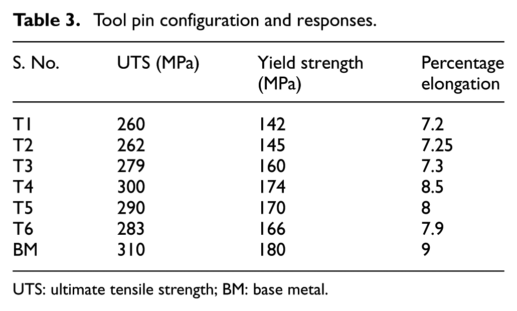
UTS: ultimate tensile strength; BM: base metal.
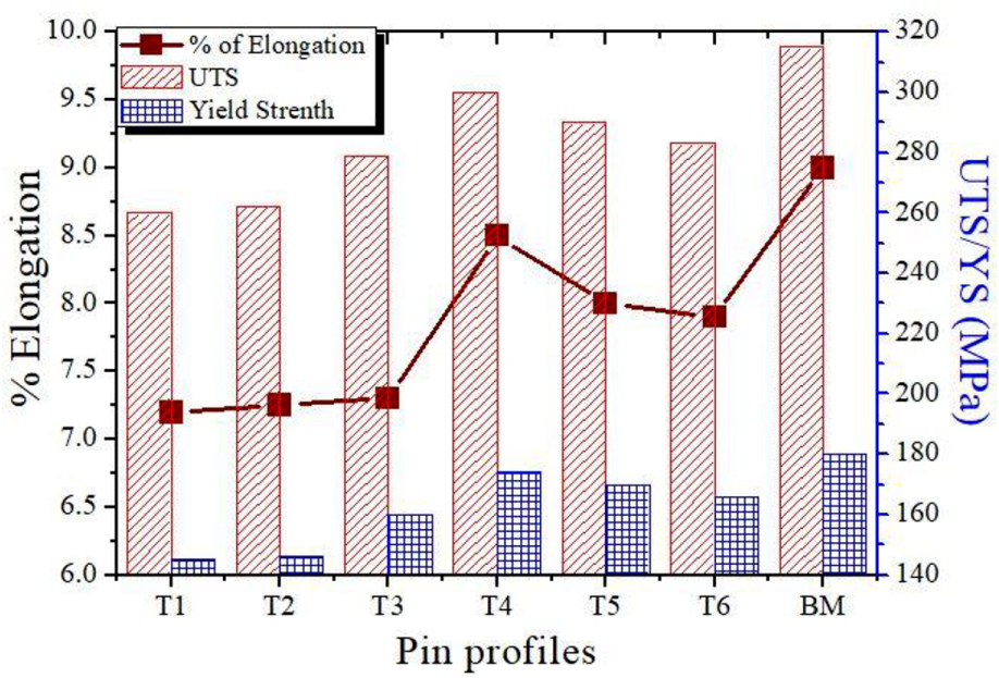
UTS, YS and percentage elongation for different pin-profiles.
Microhardness
Figure 9(a) represents the microhardness profile at the middle of the welded specimen by different pin geometries. The AA6082-T6 alloy exhibits microhardness values in the range of 115–120 HV. For tool T1, the microhardness decreased gradually on both sides from the middle of the cross-section. A minimum of 62 HV hardness is observed between thermomechanically affected zone (TMAZ) and heat affected zone (HAZ) by tool T1 on AS and 81 HV at the center of the NZ. For tool T4, the hardness increases rapidly to 92 HV after attaining a smallest value of 65 HV. This is an indication of a W shape profile of microhardness. Microhardness is correlated with microstructural properties of the FSW joint for aluminum alloys. It is familiar that the softening of microhardness in the NZ is due to the dissolution and coarsening of second-phase particles (strengthening particles) because of a thermal cycle during FSW.24–26 The microhardness in TMAZ also decreased due to the presence of coarse elongated grains near TMAZ boundaries according to Hall–Petch equation.17,27 The second-phase particles may be reprecipitated in the NZ due to heat generation and natural cooling of the joint after FSW. This is in agreement with the differences in the microhardness profile for different tool-pin geometries. The hardness in the NZ is higher than that of TMAZ and HAZ. This is due to the post-weld natural aging process, which resulted in further precipitation of strengthening.28,29 Therefore, it can be concluded that minimum temperature is obtained using tool T4 that results in less dissolution of strengthening particles than other tools. As a result of this, maximum hardness is obtained by tool T4 in the weld NZ. For all fabricated joints, the microhardness hardness on the AS is lower than the RS. This is due to higher heat generation on the AS than the RS. 16 In addition, square pin-profile has moderate swept volume ratio and higher pulsating action. Owing to re-entrant features of this profile, it produced fine equiaxed grains in the NZ with constant dispersal of strengthening precipitates, which results in the enhancement of microhardness. 13
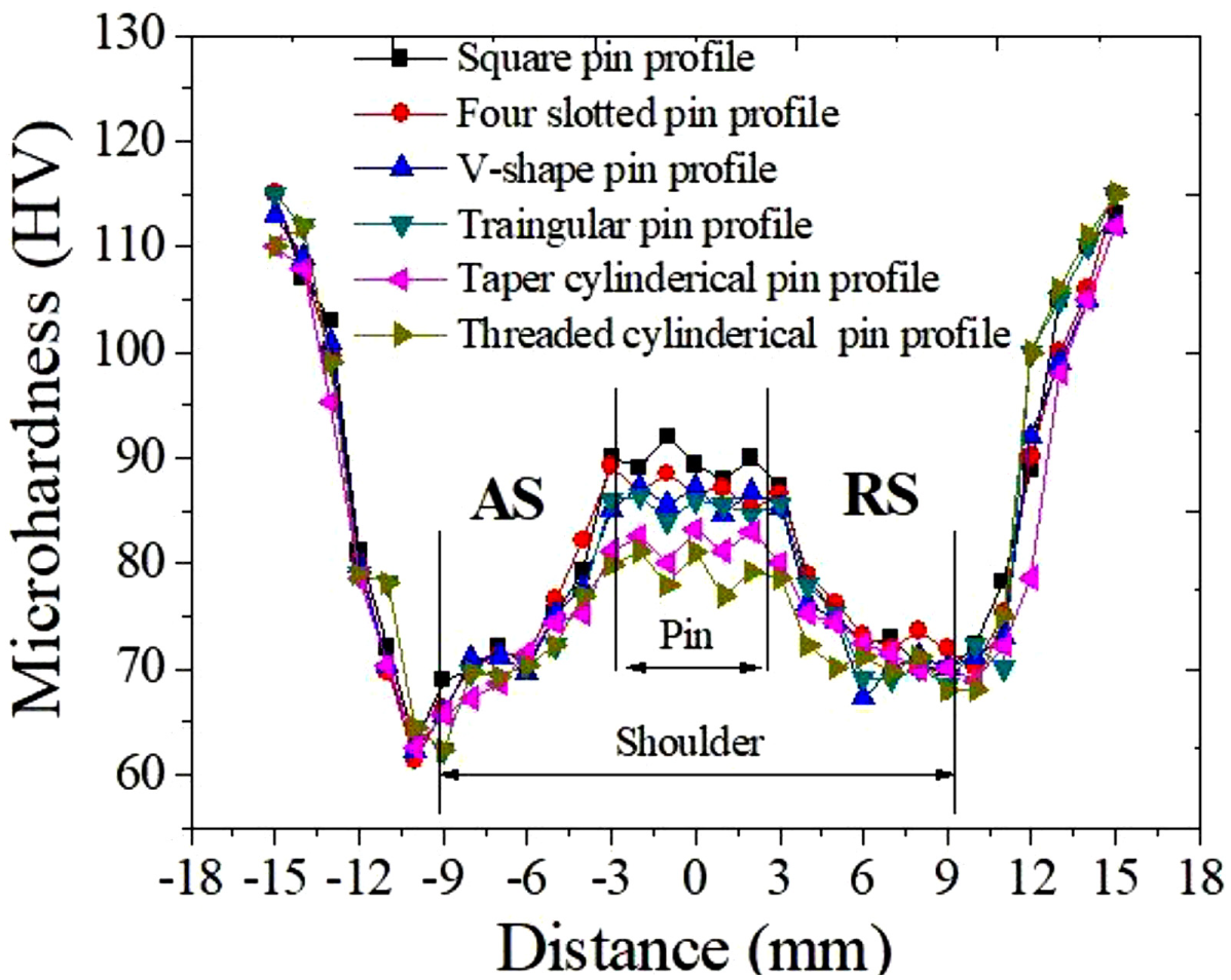
Microhardness distribution for different pin geometries.
Macrostructure analysis
Table 4 shows the macrostructure of a cross-section of AA6082 metal welds for different pin-profiles. Each fabricated joint in this investigation is analyzed using an optical microscope to obtain the macrographs. Fabricated joints are defect (e.g. voids, tunnel and small holes) free. In addition, typical onion rings are observed in the NZ for T2–T6. FSW is a mimic of extruding process. In FSW, for each rotation of cylindrical tool, a semi-cylindrical layer of metal at the front of tool is heated and extruded to the back. It results in formation of onion rings. In this study, though six different pin-profiles are employed, their dynamic volume is the same (i.e. cylindrical), resulting in the formation of onion rings except T1, which is attributed to the generation of high frictional heat owing to presence of threads on the profile, resulting in vanishing of onion rings. Similar findings are reported by Biallas et al. 30 and Krishnan. 31
The macrostructure of FS welded AA6082 joint fabricated by different pin-profiles.
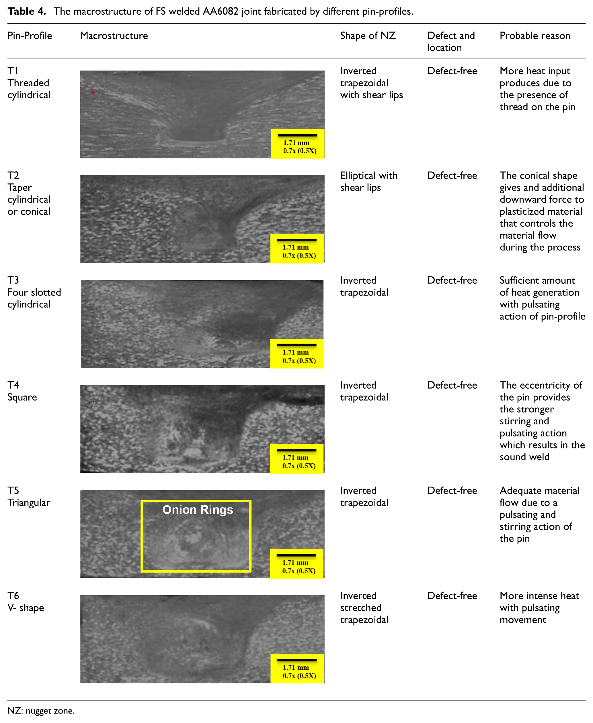
NZ: nugget zone.
These pin-profiles with eccentricity provide a pulsating-stirring action, which results in proper mixing of material in the NZ. 10 Moreover, the size (area and width) of the NZ is not identical for all pin geometries. The shape of the NZ for sample A is inverted trapezoidal with shear lips, that is, larger area and width. This is due to higher heat produced by tool T1, which results in softening of material around the stir zone. Conical pin-profile has no pulsating movement, which results in poor mixing of material than T3–T6. It also exerts a downward force on extruded material that results in decrement of upward flow capacity of the plastic material. Owing to this, improper mixing of material takes place that causes degradation of tensile properties.
Microstructural analysis
Figure 10 illustrates EBSD maps of the BM and NZ of each fabricated joint of this study. Fine equiaxed grains are observed in the NZ, which is the indication of the dynamic recrystallization during FSW. This dynamic recrystallization attributes toward more plastic deformation, which results in nucleation and growth of new grains. This growth of fresh grains is experienced by the movement of high angle grain boundaries (HAGBs). Various mechanism related to the dynamic recrystallization has been studied by researchers, that is, continuous and discontinuous dynamic recrystallization, dynamic recovery and so on.32,33 The variation of size in the NZ depends on the recrystallization mechanism. It is clear from the figure that the BM consisted of large elongated grains as compared to FSW process. The two types of boundaries are generated, that is, HAGB and low angle grain boundaries (LAGBs). The grain boundaries below 15° misorientation angle are termed as LAGB, and if the misorientation angle is greater than 15°, they are defined as HAGB (Figure 11). HAGB represents different grains, and LAGB represents the same color grains with a separate boundary as presented in Figure 10(a). The average grain size of the BM after rolling condition is found to be 21.3 μm. During FSW, due to dynamic recrystallization in the NZ, fine equiaxed grains are observed under all welding conditions as shown in Figure 10(b)–(g). Table 4 reveals the estimated grain size by EBSD analysis for NZ obtained by T1–T6. T1 and T2 have comparatively higher grain size in the NZ. The grain size obtained by T4 is found to be the smallest. It establishes that pin-profiles have a significant effect on material flowability and deformation in the NZ; resulting in variation of grain sizes.20,34 For T1, heat generation is more than other tool pin-profile, but due to no pulsating movement, mixing of material reduces, resulting in increase in grain size. For tapered pin-profile, the grain size is also similar to the grain size of the threaded pin; this is due to the additional downward force acting on the extruded material that reduces the flowability of the material about the pin. The remaining pin-profile has other feature of pulsating stirring which results in a decrease of grains size in the NZ. These pulsating movements produced by the tool are due to the associated eccentricity that produces additional frictional heat and improves plastic deformations. It is likely to stimulate the dynamic recrystallization in the NZ that causes decrement of grain size as shown in Figure 10(c)–(g). Moreover, square pin-profile with stronger stirring action (i.e. 133 pulses/s) attributes toward material flow movement. Owing to this, grain size of the NZ reduces. In addition, pin-profiles T3 and T6 also reduced the grain size than T1 and T6 owing to the presence of pulsating action and swept volume ratio.
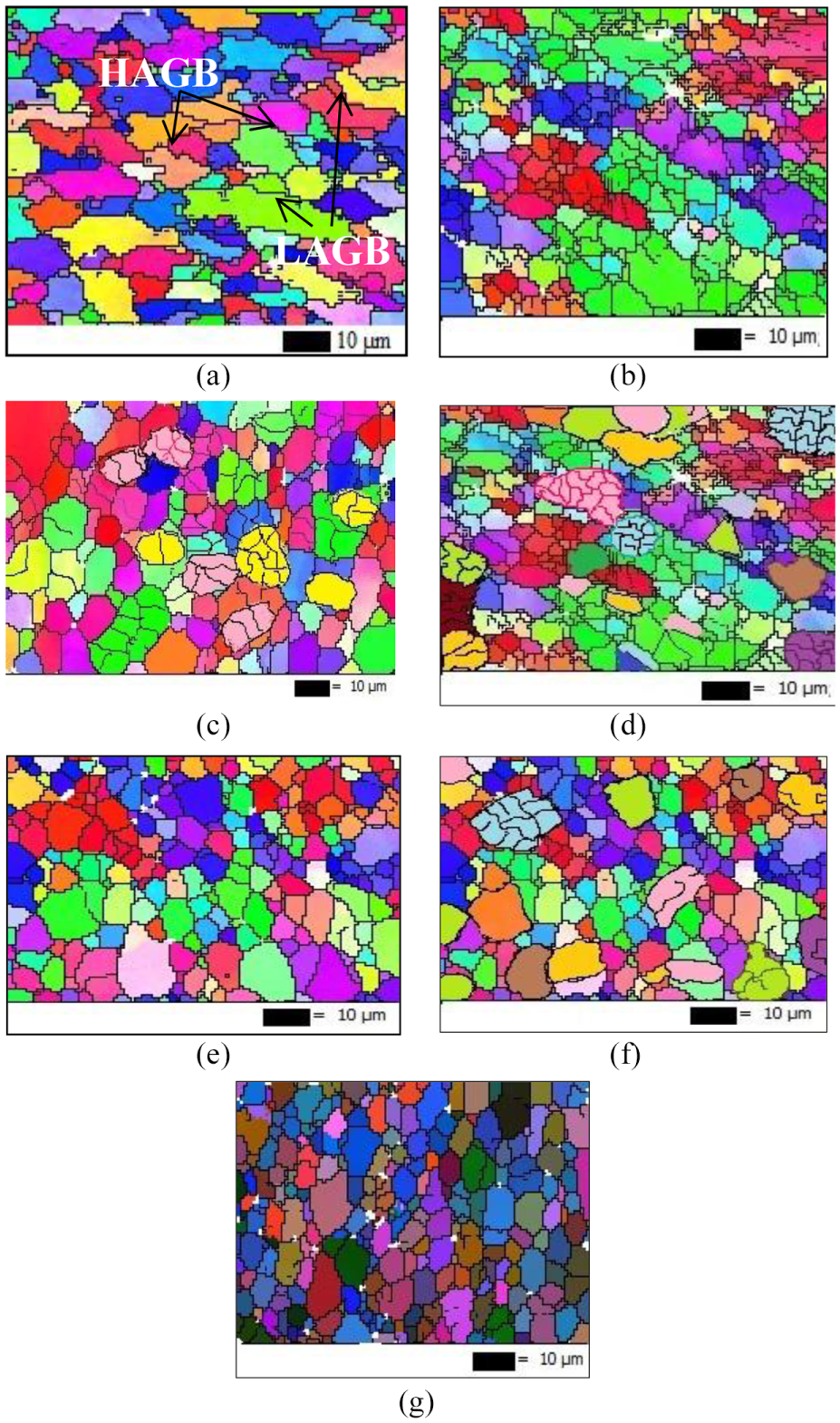
(a) EBSD map for parent metal and (b)–(g) EBSD maps of fabricated joints by T1, T2, T3, T4, T5 and T6 tools.
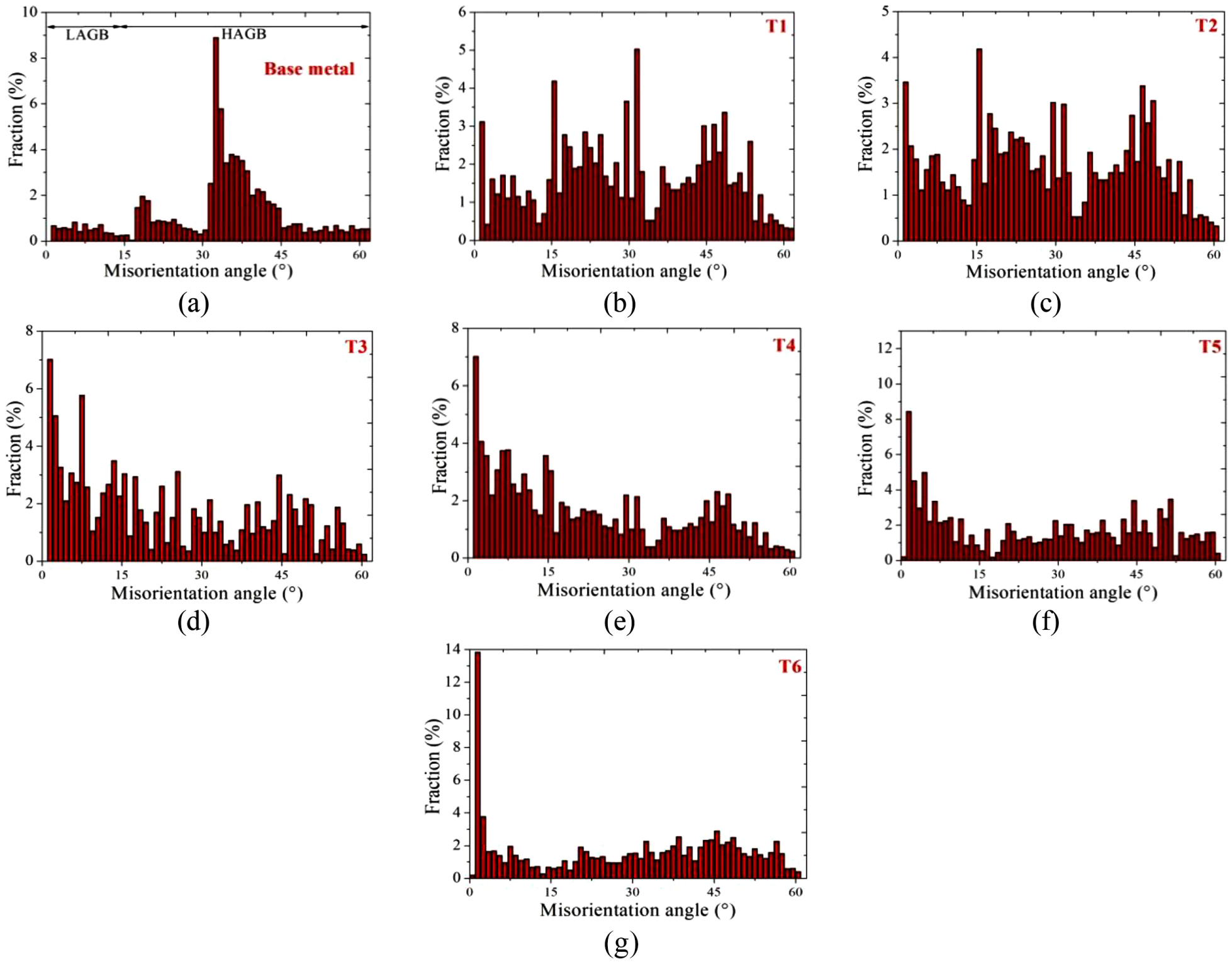
Misorientation map for different pin-profiles. Misorientation map for parent metal and different pin-profiles joints: a) parent metal; b) T1; c) T2; d) T3; e) T4; f) T5 and g) T6.
The distribution of misorientation angle for the BM and FSW joints are shown in Figure 11. It is clear from Figure 11(a) that the fraction of HAGB is comparatively higher in BM. The reason is grain refinement in the NZ owing to dynamic recrystallization during FSW. This finding is in line with the finding of Yadav and Bauri. 35 Table 5 reveals the effect of tool pin-profile on percentage fraction of HAGB. It is observed that pin-profiles significantly affect the grain size of the NZ and the percentage fraction of grain boundaries. 36 Percentage fraction of HAGB is found to decrease with decrease in grain size of the NZ. Maximum HAGB fraction is observed in the case of T1, whereas minimum is observed in case of T4. It is encountered as the pin-profiles control the material flow behavior and heat generation during the process.
Effect of pin-profiles on average grain size and grain boundaries.
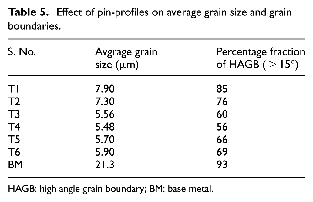
HAGB: high angle grain boundary; BM: base metal.
Fractography
The locations of fracture in tensile specimens are shown in Table 6. Cup and cone-type/ductile fracture is observed in all the cases. In this study, the tensile fracture occurred in two different locations, that is, the NZ and the HAZ. Fracture in the NZ is a common phenomena for FSW joints. In this fracture zone, crack initiation sites are not related with any softening region in the NZ. The joint obtained using T4 and T5 are fractured from the HAZ, whereas other joints are fractured from the NZ. This is attributed toward higher pulsating-stirring action of pin with sufficient amount of swept volume ratio. The micrographs of fracture surface of highest and lowest strength specimens are shown in Figure 12. Higher number of dimples (i.e. small and larger) are observed on the fracture surface of both the tensile specimens. This is an indication of ductile fracture. Figure 12(a) shows the small and deep dimples with torn edges indicating less ductility. In contrast, larger and shallow dimples are observed on the fracture surface of joint obtained by T4 as shown in Figure 12(b). This is an indication of proper mixing of material and high plastic deformation during the process caused by pulsating-stirring action with sufficient swept volume ratio.
Fracture location for different pin-profiles.
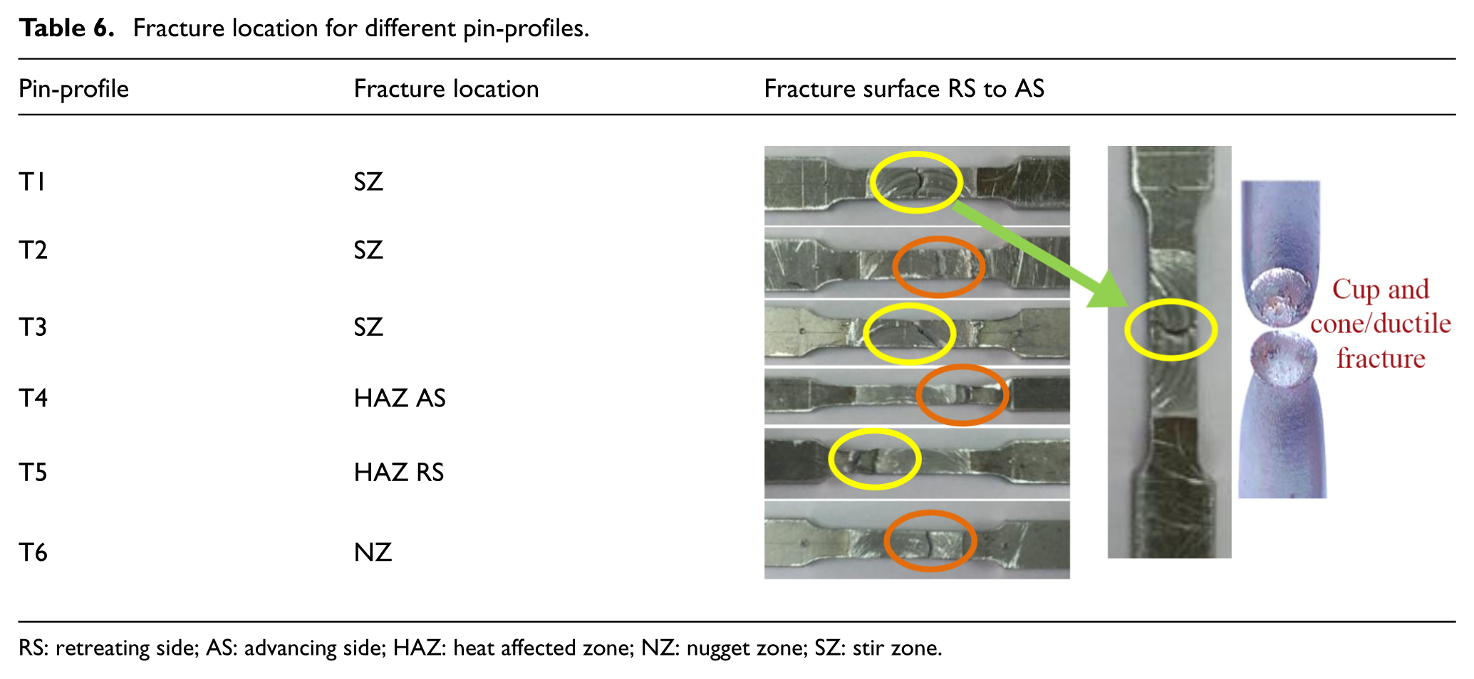
RS: retreating side; AS: advancing side; HAZ: heat affected zone; NZ: nugget zone; SZ: stir zone.
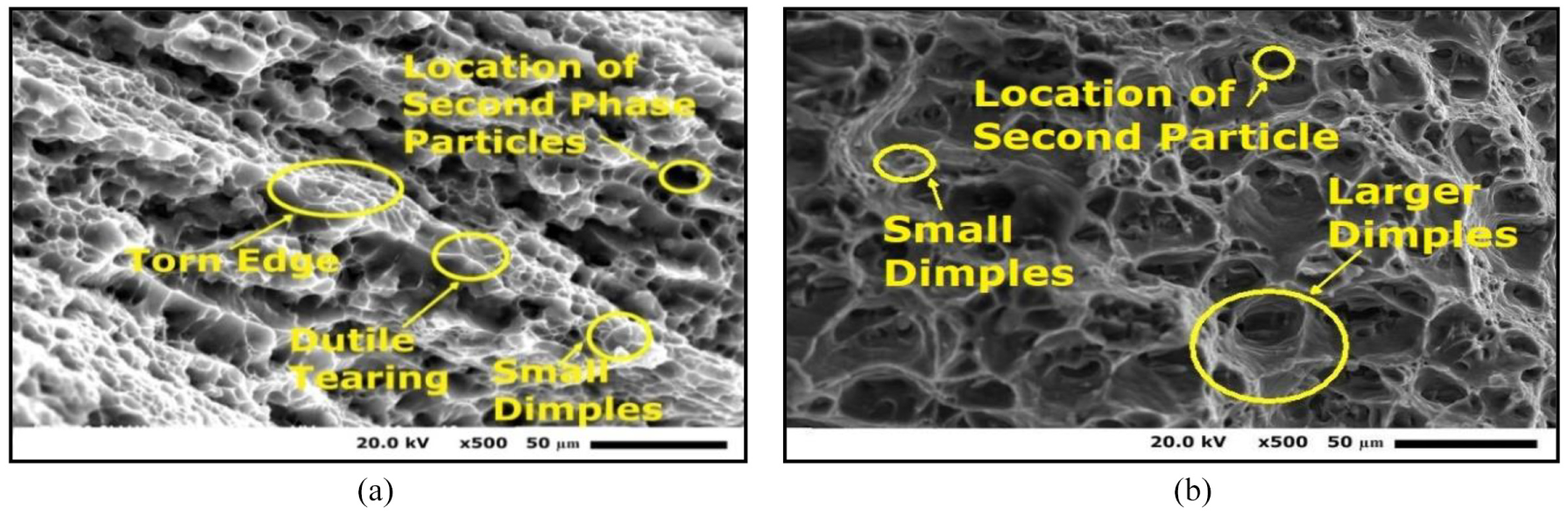
Fracture surface of joint fabricated by (a) T1 and (b) T4.
Conclusion
In this study, six different pin-profiles are developed for FSW of 6.35-mm thick AA6082-T6 plates. The effect of pin geometries on weld characteristics of FSW joints is investigated. Threaded cylindrical pin-profile produced maximum heat input during the process than other pin-profiles. Conversely, minimum heat input is evident for square pin-profile. Thus, pin-profiles significantly affect the thermal cycle of FSW. It is also observed that, AS temperature is higher than the RS. This confirms non-symmetrical heat generation during the process. These variations in heat generation due to pin-profiles affect the mechanical properties of the FS welded joint. The best tensile performance that is, ultimate tensile strength (UTS), yield strength (YS), and percentage elongation are obtained (300, 175 MPa and 8.5%, respectively) for square pin-profile. In this study, effects of two indigenously developed pin-profiles (four slotted and inverted tapered with two flat faces) are explored. It is observed that the tensile properties obtained for joints fabricated by these two pin-profiles are better than threaded cylindrical and tapered cylindrical pin-profile. These are attributed to its pulsating-stirring action and comparatively higher value of swept volume ratio. It can also be concluded that pulsating action has a significant effect on thermal cycle of FSW that attributed toward the variation in weld properties of the joints. It is observed that moderate swept volume ratio with high pulsating action produces sound welds. Furthermore, it is evident that pin-profiles also affect the grain size of the NZ. The minimum grain size is obtained for a joint fabricated using square pin (i.e. 5.48 μm). This is occurred owing to its higher pulsating-stirring action. In this study, it is experienced that joints are fractured from two different locations. Joints prepared by square and triangular pin are fractured from HAZ, while other joints are fractured from the NZ. The reason is proper mixing of material in the NZ owing to pulsating-stirring action.
Footnotes
Declaration of conflicting interests
The author(s) declared no potential conflicts of interest with respect to the research, authorship, and/or publication of this article.
Funding
The author(s) received no financial support for the research, authorship, and/or publication of this article.