
Abstract
Carbon fiber–reinforced plastics are now widely used in various industries because of its excellent properties. Although milling and drilling are the dominating processing methods for carbon fiber–reinforced plastics at present, laser beam machining, as a wear-free, contactless and flexible process, is considered a promising alternative method. However, the thermal damage is one of the most important issues for laser beam machining of carbon fiber–reinforced plastics because of the significant difference in thermal properties of carbon fiber and matrix. Water jet–guided laser technique has been proved an effective technique to reduce heat damage. Nevertheless, there are few studies about carbon fiber–reinforced plastics processing with water jet–guided laser to date. It is important to understand the mechanism of interaction between water jet–guided laser and carbon fiber–reinforced plastics. Hence, a three-dimensional finite element model was developed to investigate the transient thermal process. The influence of scanning speed on the surface appearance, heat-affected zone and shape of the cross section was illustrated. Experiments with same process parameters were conducted to validate the model. Based on the finite element model and experiments, the mechanism of material removal was explained. The epoxy is considered to be removed once it reaches the melting point and the carbon fiber is removed at the sublimation temperature. Because of the strong cooling effect of water jet, there is nearly no heat accumulation between pulses, leading to the constant heat-affected zone width at different scanning speed. The kerf sidewall is relatively vertical due to the homogeneous power distribution in water jet. The results demonstrate that water jet–guided laser cutting of carbon fiber–reinforced plastics has some advantages than traditional laser beam machining and is a potential processing method for carbon fiber–reinforced plastics.
Introduction
Due to its high strength-to-weight ratio, specific stiffness and corrosion resistance, carbon fiber–reinforced plastic (CFRP) is now widely used for structural components in various fields, such as aerospace industry, automotive industry and sport equipments. 1
At present, milling and drilling are the main processing methods for CFRP. However, these conventional machining methods still have problems to be settled such as some undesirable damages (delamination, fiber pull-out and de-bonding) and serious tool wear. 2 Because CFRP is a kind of anisotropic and layered composite laminate, it is easy to produce defects under the force input. Delamination has been recognized as a major damage of CFRP. Many researchers have conducted experiments to study the mechanism of delamination3,4 and the effect of input variables such as feed rate, cutting speed and point angle of drill bit.4–6 However, the response to machining tool varies greatly during processing because the epoxy is soft, while the carbon fiber is hard and brittle. The variations in mechanical properties and stiff carbon fibers can lead to serious tool wear.4,7 Nowadays, many new mechanical machining operations, such as vibration-assisted drilling 8 and rotary ultrasonic elliptical machining, 9 have been developed; however, the problems above are still not fully resolved. In view of this, a better processing method for CFRP is needed and laser cutting is considered a promising alternative method.
Laser cutting as a non-contact processing method is competitive in many fields because of its notable advantages: no mechanical cutting force, no tool wear, greater flexibility and easy automation. Many researchers have studied the characteristics of laser cutting of CFRP through experiments. Staehr et al. 10 investigated the heat-affected zone (HAZ) of CFRP in laser cutting with two different laser sources: one continuous wave (CW) laser and the other nanosecond pulsed laser. The nanosecond pulsed laser provided better result than CW laser in terms of HAZ width, but the thermal damage was still serious. Bluemel et al. 11 also demonstrated that comparing with the pulsed laser, the CW laser source provided bigger HAZ and lower tensile strength, but higher effective cutting velocities. Fujita et al. 12 investigated cutting efficiency and HAZ with various laser sources, whose wavelength varied from ultraviolet (UV; 266 nm) to near-infrared (NIR; 1064 nm) and pulse width varied from 100 fs to 20 ns. They drew the conclusion that shorter wavelength resulted in smaller HAZ appearance because of the higher absorptivity. Wolynski et al. 13 also demonstrated that the quality of CFRP ablation depended strongly on the operating wavelength. The maximum HAZ at 1064 nm was almost doubled compared to that at 532 nm according to their experiment results. Choudhury and Chuan 14 used single- and double-pass to cut glass fiber–reinforced plastic (GFRP) composite. The response surface methodology was taken to plan and design experiments to study the relationship between input laser cutting parameters and the output such as kerf width, taper and surface roughness. They got the conclusion that double-pass laser beam produced better surface appearance. Multi-pass laser beam was proved an effective method to improve the surface quality;11,15,16 however, the thermal damage still could not be avoided.
In addition to experiments, many researchers studied the interactions between laser and CFRP through theoretical analysis and numerical simulation to reduce the thermal damage. Negarestani et al. 17 developed a three-dimensional (3D) finite element (FE) model for simulating the transient temperature field and subsequent material removal based on the “element birth and death” technique of ANSYS. Temperature distribution and ablation depth of CFRP at different laser scanning speeds were successfully predicted in the finite element analysis (FEA). This study showed feasibility of adopting FEA method to laser cutting of CFRP and indicated that increasing scanning speed was a way to reduce HAZ. Boley and Rubenchik 18 developed a ray-trace model to determine the absorptivity and absorption depth within the composite materials. The model can calculate the energy deposition and predict the thermomechanical behavior under high power laser radiation. Ohkubo et al. 19 adopted finite difference method to calculate heat transfer in laser processing of CFRP. The heat generation of oxidization of materials, which was ignored by others, was considered in numerical simulation.
As we can see from the above, laser cutting of CFRP still has challenges because of the thermal damage. The inhomogeneous thermal properties of CFRP made the problem more serious. Water jet–guided laser method was proved to be an effective technique to reduce heat damage.20,21 During water jet–guided laser machining process, the water jet acts as an optical fiber and conveys the laser to the surface of workpiece. The laser heats the material, while the water jet can efficiently expel the melt from the cut and cool it. However, there are few studies about CFRP processing with water jet–guided laser to date. Therefore, unidirectional CFRP were adopted to conduct experiments with water jet–guided laser technique. In order to understand the mechanism about the interactions between CFRP and water jet–guided laser, a 3D FE model was developed with ANSYS to study the transient thermal distribution and ablation principle in this article.
Experimental setup
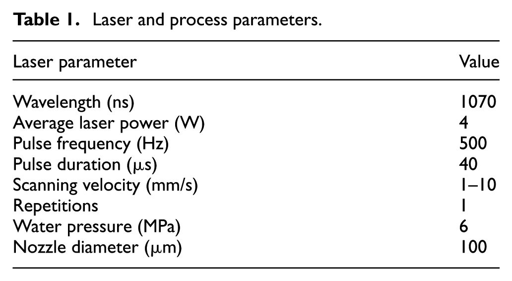
The laser source used in experiments is a HS series laser produced by SPI Lasers UK Ltd. The laser source is a continuous-wave (CW) laser with a maximum average power of 400 W at a wavelength of 1070 nm, while it can be modulated into pulses with a maximum frequency of 100 kHz. All experiments were performed at a frequency of 500 Hz, pulse duration of 40 µs and a maximum peak output power of 400 W. The self-developed water jet–guided laser experiment platform, involving the water cycling system and the coupling unit, was used in experiments. In order to reduce the laser absorption, the used water is filtered, deionized and degassed. In experiments, the laser was focused into a nozzle with a diameter of micrometer. Because of the lens loss and coupling loss, the average power transferred into water jet is 4 W, which is measured by Ophir power meter. The workpiece was mounted on a computer numeric control X-Y table and the coupling unit was on the Z table. Figure 1 is a photograph of the self-developed experimental setup of water jet–guided laser. The main processing parameters are summarized in Table 1.
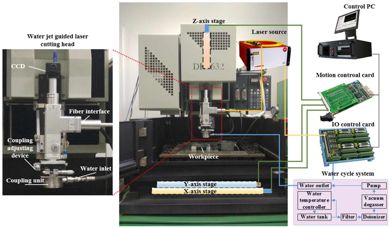
Photograph of water jet–guided laser equipment.
Laser and process parameters.
FE modeling
Geometric model
The single-pass cutting was studied in the current research. In this case, the integrity of water jet can be ignored because the ablation depth is not too deep to influence the transmission of laser. Therefore, the cooling effect of water jet was taken into account as a strong convection cooling coefficient and the flow of water is neglected.
Previous numerical simulation usually considered CFRP as a simple uniform mesh with anisotropic material properties. The assumption could simplify the model and reduce computational time, but made a deviation between simulation and actual result. In this article, the fiber and epoxy were meshed separately, which increased the number of elements and then lead to more computational time and space consumption. The model was also restricted to a small portion of the actual workpiece because of the limitation of PC. Nevertheless, the treatment could provide better insight into the phenomena of CFRP machining and gave more accurate simulation results. In order to reduce the calculation time and space used, the model adopted unidirectional carbon fiber and was established by symmetry. Therefore, in both FE model and experiments, an epoxy-based CFRP composite laminate with fully unidirectional carbon fiber was used. The diameter of carbon fiber was 7 µm and the volume fraction of carbon fibers was about 60%. The dimensions of the mesh geometry were adopted as 204 µm × 204 µm × 150 µm, which was enough for analyzing a single pass of the laser beam. The cutting path was modeled on the mesh edge of Z direction and was perpendicular to the direction of carbon fiber. The height of 204 µm was the optimum to analyze the actual ablation depth after a single pass according to the previous experiments. Figure 2 is the sketch of FE model. The wireframe represents the symmetric workpiece that is excluded in the FE model. Figure 3 illustrates the 3D mesh of the FE model with different regions representing carbon fiber and epoxy matrix.
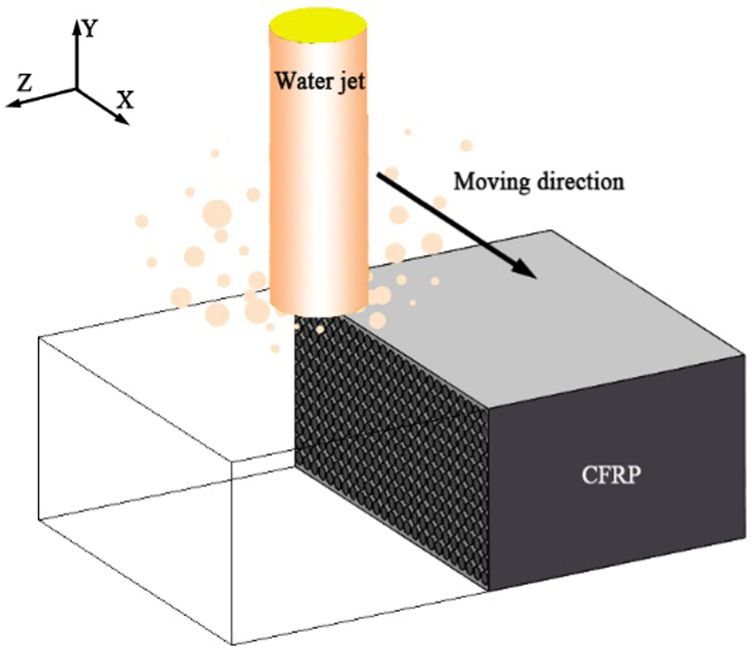
Sketch of finite element model.
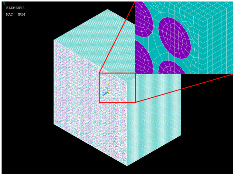
Mesh of the finite element model.
In order to simulate the transient thermal behavior and subsequent material removal, the element birth and death technique of ANSYS was adopted. Thus, the material removal condition has a great influence on the simulation accuracy. The assumptions about material removal in the model included the following:
With the increase in temperature, epoxy will occur melting and pyrolysis. Taking into the impact force of water jet, the epoxy can be supposed to be washed away after it reaches the melt temperature.
Under the effect of laser irradiation, the carbon fiber will undergo oxidation or sublimation depending on whether there is oxygen or not. 22 The sublimation temperature is very high (about 3316 °C). The heating region was impacted by the water jet and the used water is deionized and degassed, so the sublimation temperature was taken as the removal temperature.
Material properties
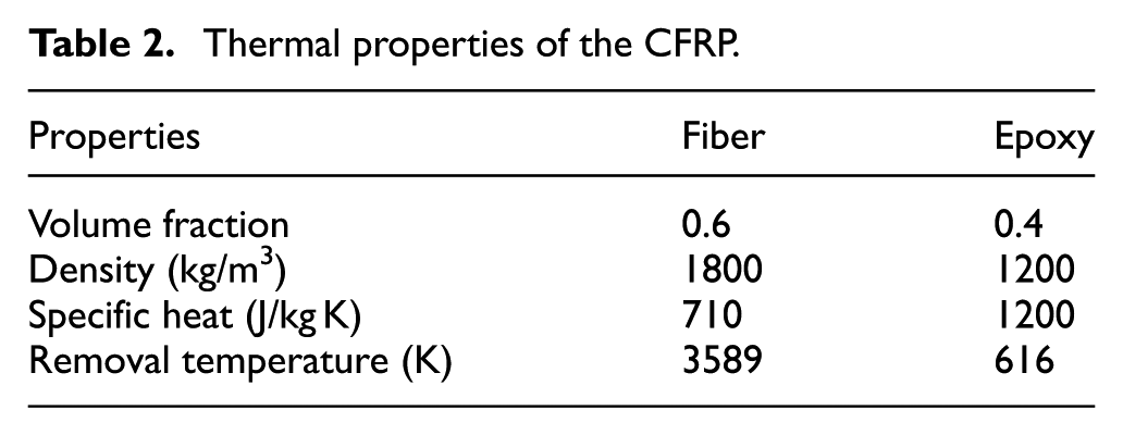
The thermal properties of carbon fiber and epoxy are listed in Table 2.17,19,23 Moreover, in order to generate a realistic model, temperature-dependent anisotropic thermal conductivity of the material was used, which is shown in Figure 4.
Thermal properties of the CFRP.
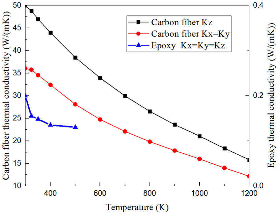
Anisotropic temperature-dependent thermal conductivity of carbon fiber and epoxy.
Governing equations and boundary conditions
Time-dependent heat conduction equation
In this study, transient heat conduction was the major consideration. Therefore, the governing equation was time-dependent heat conduction equation as follows
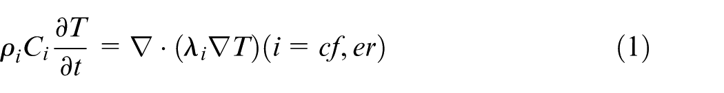
where
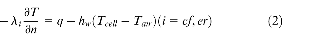
Boundary conditions
At the top surface where the laser flux and water-cooling effect were applied, the convective boundary conditions were considered in equation (2). Other surfaces in the top side were considered as natural convection boundary condition, as shown in equation (3). All surfaces except the top side were considered as adiabatic in equation (4)
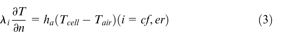
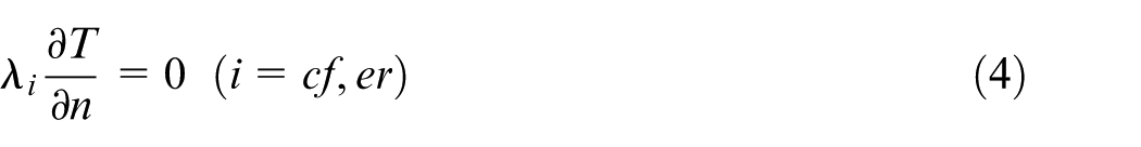
In the above equations, n is the normal vector of surface and
The laser emitted by the laser source was Gauss distribution originally. However, the water jet, which behaved as a multimode waveguide, could change the Gauss distribution to nearly homogeneous distribution over the whole jet cross section. 24 Better homogeneity over the entire water jet could be obtainable by decentering the coupling of laser and jet. Therefore, the laser absorption heat flux was considered as homogeneous distribution and was given by
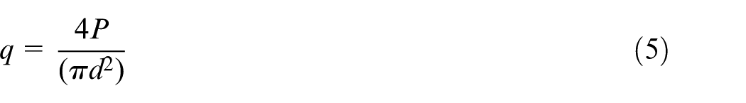
where P is the peak power of pulsed laser and d is the diameter of water jet. At the beginning of simulation, the heat flux was applied on the surface of material. During the numerical simulation, the material removal process was updated at the end of every time step. Then, the program will apply the heat flux on the surface of alive elements at the end of time step.
The strong convective cooling effect of water jet was the key to water jet–guided laser processing. It was also quite important to the accuracy of numerical simulation. In this study, the research results of Liu 25 were taken to calculate the strong convection coefficient of water jet
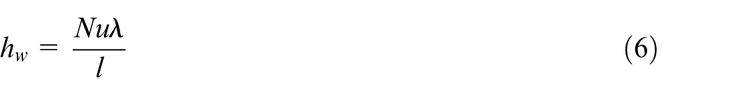
where
Simulation results
Based on the FE model, the numerical simulation was conducted with different scanning speed. Scanning speed varied from 1 to 10 mm/s, and other process parameters (frequency of 500 Hz, pulse width of 40 µm, and average laser power of 4 W) were kept constant.
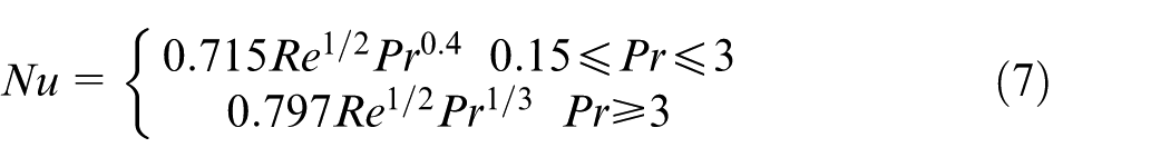
Figure 5 shows the machining process of CFRP at the scanning speed of 4 mm/s. Figure 5(a) is the beginning of machining process. Figure 5(b) and Figure 5(c) are two moments during the machining process. Figure 5(d) is the end of machining process. As the laser beam moved forward, the material was continuously removed, and finally a cutting groove was formed. The unit of the time was second, and the bottom column of numerals corresponding to different colors represented the temperature of the CFRP. As we can see from Figure 5, the color of CFRP is all blue, which means that the temperature is all 25 °C. That was because the simulation process was a cycle of heating and cooling due to the use of pulse laser, while the picture was taken at the end of the cooling process.
Machining process at the scanning speed of 4 mm/s: (a) The beginning of machining process, (b and c) two moments during the machining process and (d) the end of machining process.
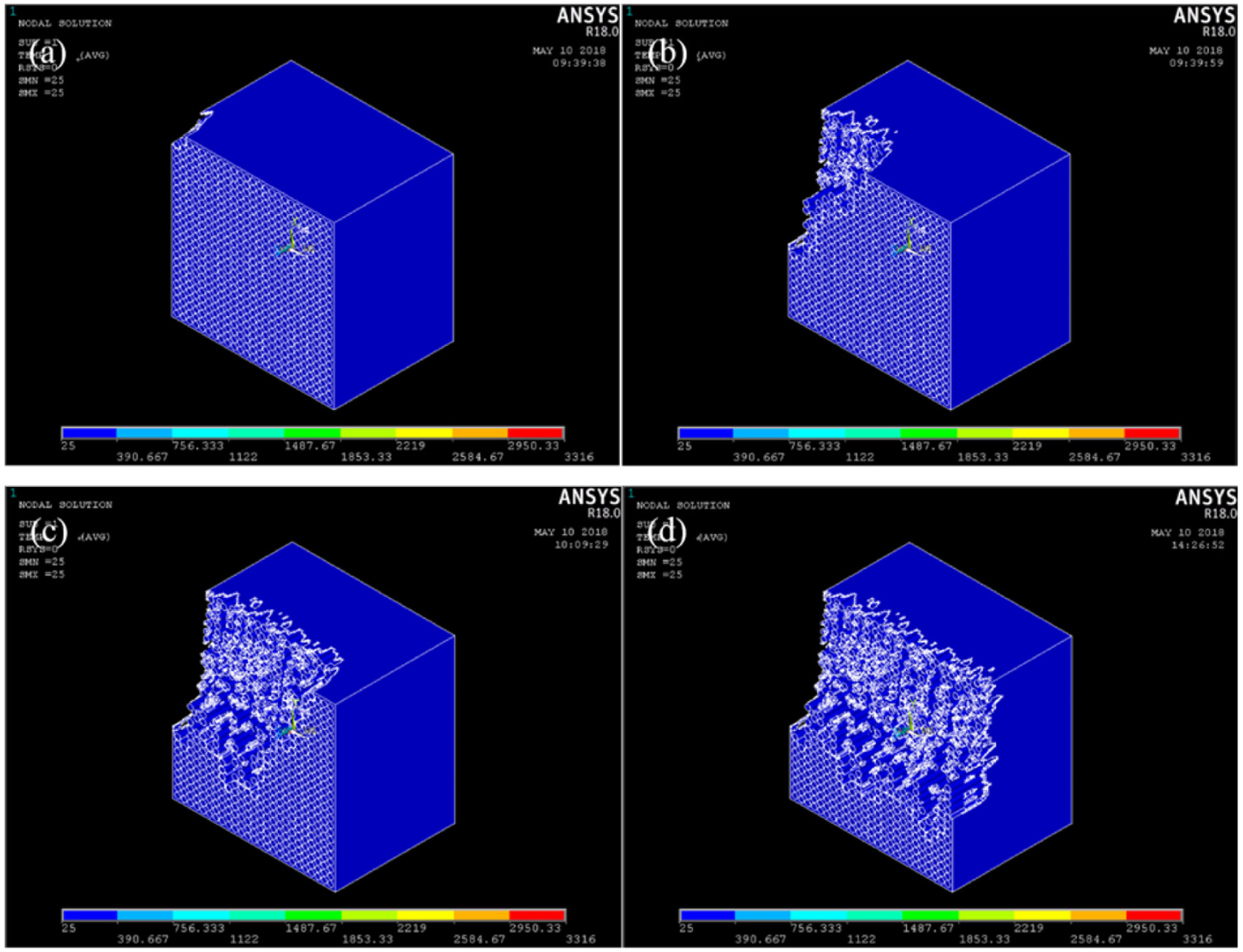
In order to further study the temperature variation process, the temperature distribution which was taken after a laser pulse and after a cooling process was compared. Figure 6(a) showed the temperature distribution after a laser pulse, the region whose temperature exceeded the sublimation point of carbon fiber and melting point of matrix had been removed, while the temperature of the adjacent region remains higher than room temperature. However, the whole model has restored to room temperature after the following interpulse period, as shown in Figure 6(b). It can be seen from Figure 6 that the fiber pull-out still exists near the cutting region, although there is a strong convection cooling effect induced by the high-speed water jet. The instantaneous heat can be conducted to the adjacent matrix and the adjacent matrix will be molten because of the higher thermal conductivity of fiber. However, the heat is only enough to melt the epoxy over a short distance, and cannot vaporize the carbon fibers.
Temperature distribution after (a) laser pulse and (b) cooling.
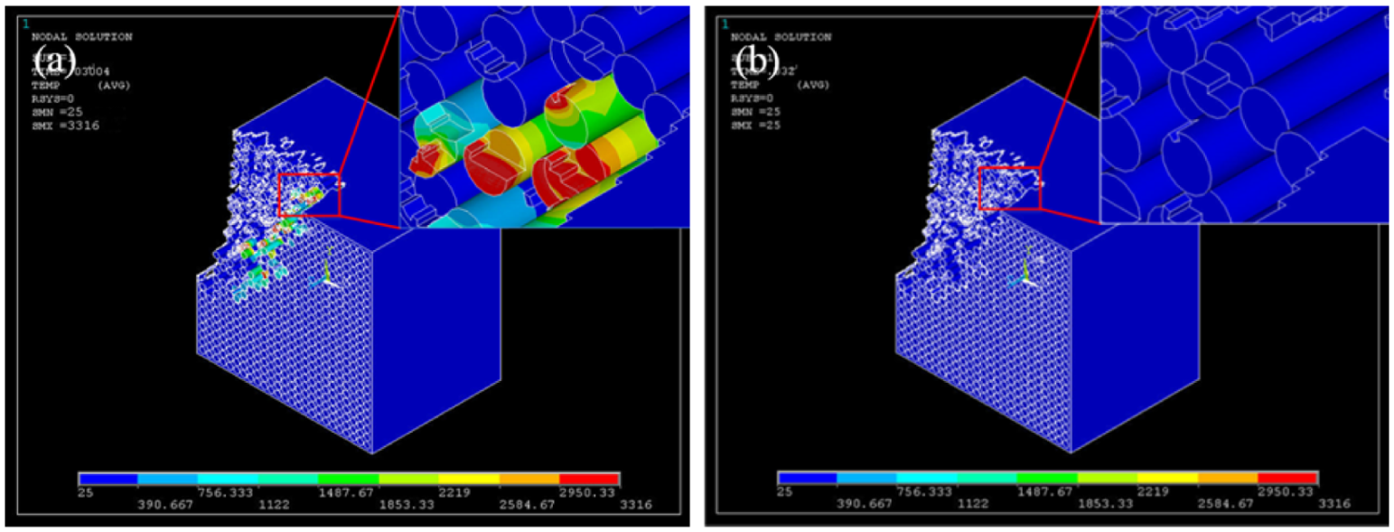
Figure 7 shows the cutting results for various scanning speeds of 1, 4, 7 and 10 mm/s. It is obvious that the ablation depth decreased with the increase in scanning speed. However, the kerf in simulation has a relatively vertical side wall. This phenomenon can be attributed to the homogeneous power distribution, which was mentioned above. Different from the Gauss distribution, any point in the homogeneous distribution has a same power density. In other words, the ability to ablate material is same in any point of the water jet cross section, which results in the relatively vertical side wall.
Simulation results at different scanning speeds: (a) 1 mm/s, (b) 4 mm/s, (c) 7 mm/s, and (d) 10 mm/s.
Experiments results
The unidirectional CFRP was selected as the experimental sample in order to compare with the FEA simulation. For comparative study, both the water jet–guided laser machining and conventional laser beam machining experiments were conducted. The processing conditions of the two experiments were the same as FE model. The surface appearance, HAZ width and shape of the cross section were selected to evaluate the effect of scanning speed in single-pass cutting.
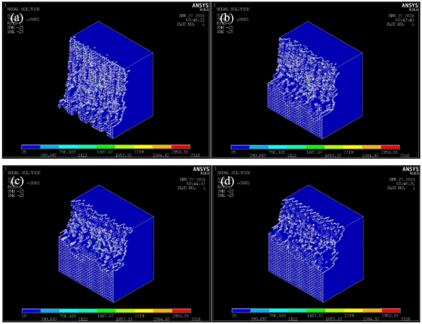
Figure 8 shows the experimental results of water jet–guided laser for various speeds of 1, 4, 7 and 10 mm/s and illustrates how HAZ width, ablation width and ablation depth were measured. The HAZ region is also indicated by the red dotted line. As shown in Figure 8, the ablation depth decreases with the increase in scanning speed. The experimental phenomena are in accordance with the simulation results presented in Figure 7. Moreover, the side walls of the grooves are almost vertical, which is also in line with the simulation results in Figure 7. Figure 9 shows the experimental results of conventional laser beam machining for various speeds of 1, 4, 7 and 10 mm/s. The ablation depth is deeper than that of water jet–guided laser machining due to the lack of cooling effect of water; however, the HAZ width is obviously larger. Therefore water jet–guided laser has great advantages in reducing thermal damage than laser beam machining. In addition, because the power density of laser is Gauss distribution in laser beam machining, the depth in the middle of the groove is deeper than the sides. In a word there are notable differences between water jet–guided laser machining and conventional laser beam machining.
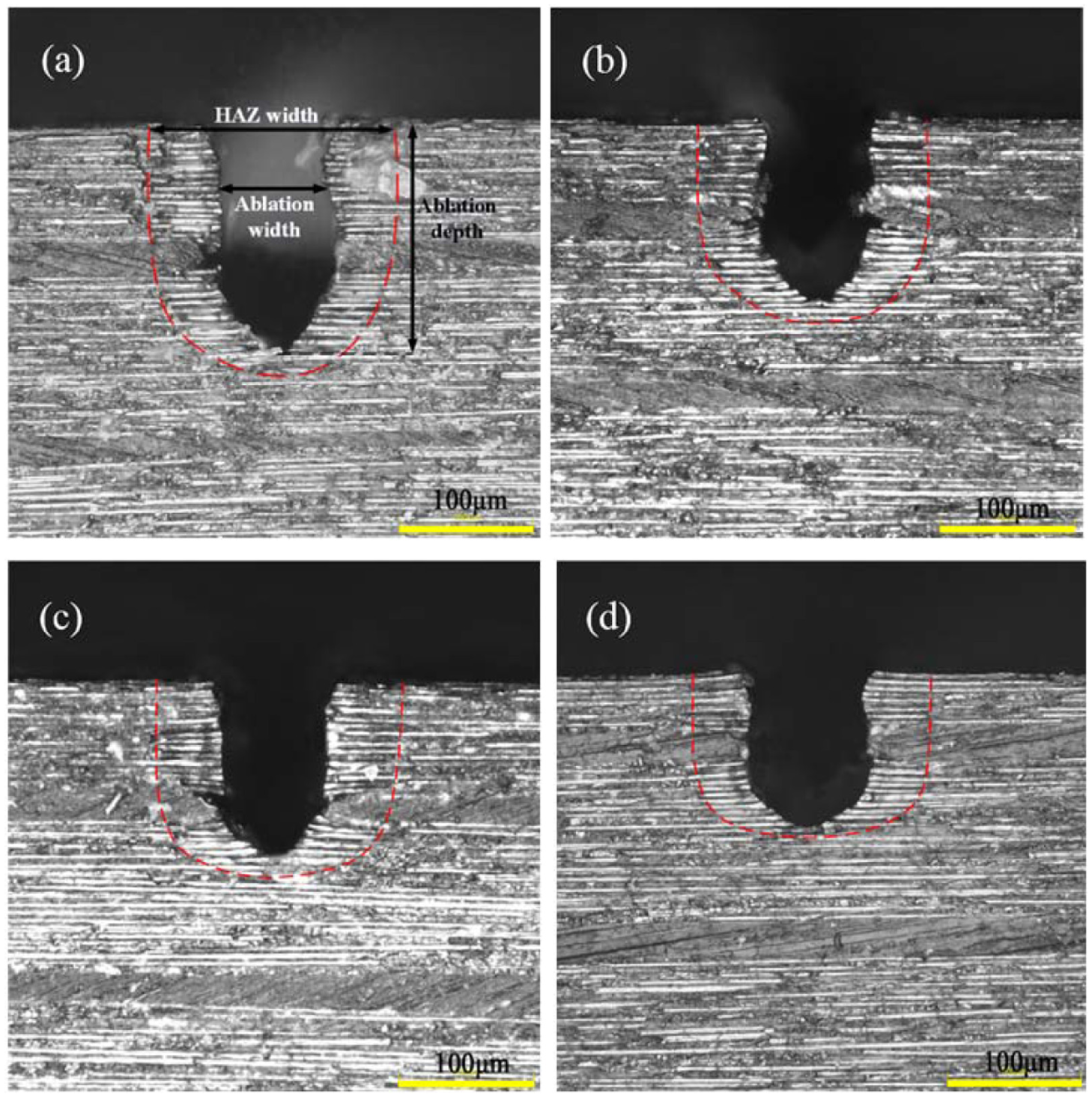
Experimental results of water jet–guided laser machining at different scanning speeds: (a) 1 mm/s, (b) 4 mm/s, (c) 7 mm/s and (d) 10 mm/s.
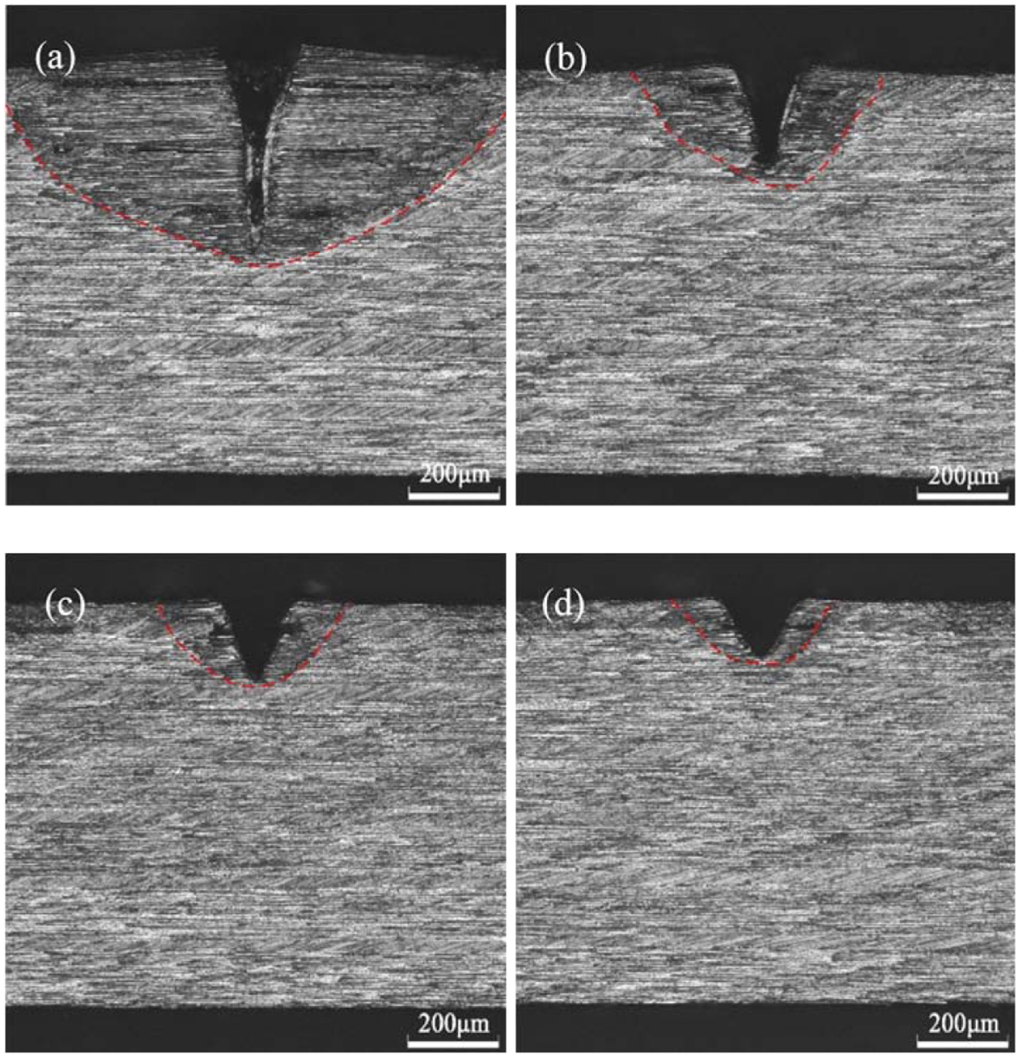
Experimental results of conventional laser beam machining at different scanning speeds: (a) 1 mm/s, (b) 4 mm/s, (c) 7 mm/s and (d) 10 mm/s.
A comparison of the HAZ width of water jet–guided laser machining and the FE method is shown in Figure 10. It can be noted that the HAZ widths of all scanning speeds are almost equal, which is different from previous studies. In conventional laser beam machining, the thermal damage would decrease as the scanning speed increased because of the reduction in the interaction time at higher speeds.10,11,17 The higher scanning speed would lead to a shorter heating phase at each point along the cut path. The same HAZ width in water jet–guided laser machining could be attributed to the high cooling effect. During the water jet–guided laser machining process, the material was heated and removed in the laser pulse duration and was cooled rapidly in the interpulse period. Different from laser beam machining in air, the water jet could cool the heated region to room temperature rapidly, that is, there was no heat accumulation effect between pulses. This conclusion had been proved by the simulation results illustrated in Figure 6. The rapid cycle of heating and cooling made the HAZ width almost the same as the scanning speed increased. However, the HAZ width predicted by FE simulation is lower than experimental results, as shown in Figure 10. The deviation reflects the complexities involved in the simulation because the model cannot satisfy all the specifications, such as the laser absorption by the water and the error of material properties.
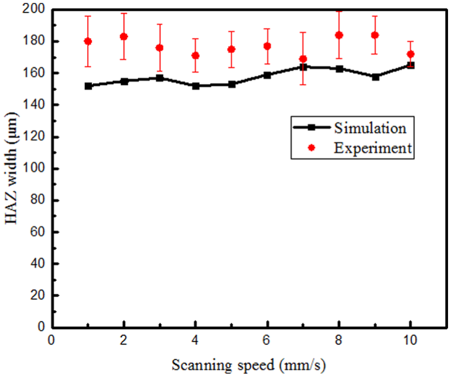
HAZ width predicted by FEA compared with experimental results of water jet–guided laser machining.
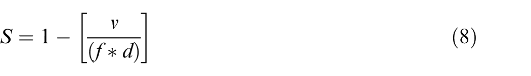
Figure 11 compares the ablation depth and width between the predicted results by FE method and experimental results of water jet–guided laser. As illustrated in Figure 11(a), the ablation depth increases as the scanning speed decreases from 10 to 1 mm/s. The trend of ablation depth is same as that of conventional laser beam machining.10,11 However, it is not the accumulation of heat, but the increase in pulse overlap rate, that increases the material removal depth. According to equation (8), the pulse overlap rate will increase with the decrease in scanning speed, which leads to multi-pulse irradiation at one point, thereby increasing the ablation depth. In equation (8), S, v, f and d are, respectively, the pulse overlap rate, scanning speed, laser frequency and the diameter of laser beam. Figure 11(b) shows the change curve of ablation width as the scanning speed increase. The kerf width almost remains the same, which is similar to that of the HAZ. Considering the contraction coefficient of nozzle (about 0.8), the width of kerfs corresponds well to the diameter of water jet
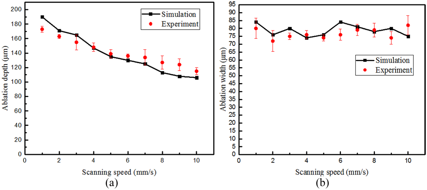
(a) Ablation depth and (b) width predicted by FEA compared with experimental results of water jet–guided laser machining.
Based on the FE model and experimental results, the CFRP removal mechanism during the water jet–guided laser processing is investigated. Despite the presence of strong cooling effect of water, pulsed laser can still heat and remove the irradiated area. The fibers can conduct heat into matrix rapidly and the heat is sufficient to melt the epoxy. Then, the epoxy can be expelled by water impact force, leading to the fiber pull-out. Before the next laser pulse is irradiated, the strong cooling effect of water jet has cooled the material down to room temperature. The laser energy of last pulse cannot accumulate to the next pulse. That explained why the HAZ area has not increased with the decrease in scanning speed. Another difference compared with laser beam machining in air is the decomposition temperature of carbon fiber. Many studies have proved that the temperature of carbon fiber cannot reach sublimation point in air because of the oxidation reaction using thermogravimetric analysis (TGA) technique. The carbon fibers will decompose at about 880 °C, and many other numerical simulations take this as decomposition temperature. However, if the simulation takes 880 °C as the decomposition temperature in water jet–guided laser processing, the ablation depth will be significantly greater than experimental value. Hence, it is more reasonable to take the sublimation point as decomposition temperature according to simulation result and actual processing condition.
Conclusion
In order to investigate the water jet–guided laser processing of CFRP, a 3D FE model using realistic mesh geometry and anisotropic thermal properties is developed. The material removal is realized by “element birth and death” technique of ANSYS. Detailed information about the process of water jet–guided laser cutting is revealed by the simulation. Surface appearance, HAZ width, kerf geometry and temperature distribution at different scanning speeds have been predicted. The simulation results show the agreement with the experiments well. The mechanism of water jet–guided laser of CFRP has been investigated using the FE model and experiments:
In water jet–guided laser processing, the epoxy can be considered to be removed after reaching the melting point because of the impact force of water jet. The carbon fibers cannot be oxidized as laser beam machining in the air, because the water separates the carbon fibers from the air. The carbon fibers will sublimate after it reaches the sublimation temperature in water jet–guided laser processing.
The strong cooling effect of water jet can cool the heated zone rapidly, resulting that there is no heat accumulation between laser pulses. That is why the HAZ width does not increase with the decrease in scanning speed.
Because of the homogeneous power distribution in water jet, the ability to ablate material is almost same in the water jet cross section. This feature allows water jet–guided laser to process vertical sidewalls.
The results of simulation and experiments demonstrate that water jet–guided laser cutting of CFRP has more notable advantages in reducing thermal damage and processing vertical sidewalls than laser beam machining. Therefore, water jet–guided laser technique is a potential processing method for CFRP and further research is needed. In order to elucidate the mechanism when the ablation depth is deep enough to influence the laser transmission, the flow of water and ray-trace should be taken into consideration in the numerical simulation in the future, and the follow-up experiments should be conducted.
Footnotes
Declaration of conflicting interests
The author(s) declared no potential conflicts of interest with respect to the research, authorship and/or publication of this article.
Funding
This work was supported by the National Key Fund of China (Grant No. 61409230307) and National Natural Science Foundation of China (Grant No. 51575308).