
Abstract
Observed two bubble growth modes indicated that the stability of arc burning and bubble growth relied on each other. Under selected welding parameters, the maximum diameters of generated bubbles complied with approximately normal distribution. Higher preset welding parameters generated larger bubbles with gradually receding influences. Vaporization, condensation, and reactions happened rapidly inside the bubbles even after detachment and when coming to water surface. Gas-assisted underwater flux-cored arc welding was proposed to improve the slag coverage. This method was also effective in achieving better weld appearance.
Introduction
The underwater wet flux-cored arc welding (FCAW) has been developed for automatic and semi-automatic welding processes. However, the complicated phenomenon due to aqueous environment limits its further improvement of quality and reliability. Researchers tried to investigate the environmental influences based on various methods, including electrical signals, spectral signals, numerical analysis, and visual signals.
Ghetiya and Patel 1 illustrated the effect of welding speed on mechanical properties and microstructure during immersed friction-stir welding. Based on the obtained electrical signals, Chen et al. 2 concluded that the arc stability of underwater wet welding was worse than CO2 welding. Jia et al. 3 collected the spectrum signals and verified the existence of H element in underwater arc plasma. Kishta and Darras 4 presented a detailed experimental study on underwater friction-stir welding of 5083 marine-grade aluminum alloy. Their results showed that underwater friction-stir welding produced good tensile properties and led to a significant reduction in the void fraction. Prakash et al. 5 used the underwater laser processing to minimize the heat-affected zone, microcracking, and burr formation around the microchannel. They also performed the optimization of process parameters to obtain desired values of microchannel characteristics.
A series of researches concerning the bubbles during underwater welding have been carried out. Tsai and Masubuchi 6 set up an idealized bubble growth model to predict bubble phenomena mathematically. Brown et al. 7 proposed that the arc bubble and the trapped or impinging gas could affect the heat transfer, which would act to eliminate sizable boiling heat transfer in this region. Łabanowski et al. 8 verified that the bubbles provided the void for arc burning and had significant effect on the stability of arc burning. Silva and Hazlett 9 measured the gas components of bubbles during underwater Shielded Metal Arc Welding (SMAW). Silva 10 proposed that varying welding parameters (welding current, arc voltage, welding speed, and polarity) for a given liquid environment, electrode, and water depth had little effect on gas flow rate and dynamic characteristics of bubble. However, Feng et al. 11 held that the welding parameters (wire feed speed and arc voltage) had its distinct influences on the bubble evolution process. They also suggested that better protective effect could be achieved with larger bubbles. Wang et al. 12 proposed that a more stable wet welding process was realized by controlling the arc bubble detachment. Based on common high-speed cameras and special optical design, Jia et al. 13 captured clear images of the bubbles, droplets, and arc behaviors. It was found that the bubble grew violently in a pulsed way with varying speeds rather than a continuous smooth way.
Above-mentioned researches provided important results about the characteristics of bubble and its effect on underwater welding process. Since the bubble dynamics is an interdisciplinary subject, references concerning bubble generated through submerged orifices in other subjects can provide more theoretical support. Dietrich et al. 14 measured the velocity flow field at micro- and macroscales of bubbles generated through a submerged orifice. Liu et al. 15 proposed that the bubble dynamics was sensitive to the disturbance of detachment process; the nozzle diameter had significant influences on it. Tsuge and Hibino 16 investigated the bubble formation from an orifice submerged in liquid. The effects of some factors on the bubble volume such as gas chamber volume, orifice diameter, physical properties of gas, and velocity of surrounding liquid were discussed. Cho et al. 17 investigated the feasibility of ultrasonic bubble nucleation in polyurethane. Classical nucleation theory and cluster theory were employed to the nucleation phenomena. They discovered that ultrasonic excitation created a good foam structure even at a low saturation pressure around 0.15 MPa (1.5 atm).
Available researches on the bubble during underwater welding have proved its importance on the stability of welding process and bead formation. However, some important mechanisms including the effect of preset welding parameters on bubble geometry and the effect of bubble characteristics on bead formation are still not fully revealed. In this study, the whole evolution cycle of bubble (from generation to break-up at the surface) during underwater wet FCAW was analyzed to further reveal the relationship between the burning arc, generated gas flow, and bubble behavior. The effect of bubble characteristics on bead formation especially on slag coverage was also analyzed. Gas-assisted underwater FCAW was applied to improve the slag coverage and the weld appearance.
Experimental procedure
Bead-on-plate welding experiments were conducted in shallow water (fresh water, 0.4 m depth) in an oblong tank. A regular welding power source Pulse MIG-500 manufactured by Aotai Electric Co., Ltd was employed to keep the arc voltage constant. Experiments were conducted in the direct current electrode positive (DCEP) mode. One lime-titania-type flux-cored wire (1.6 mm diameter) was applied. This wire was specially developed and manufactured for underwater wet welding by E.O. Paton Electric Welding Institute in Ukraine. The base material was Q235 mild steel with the dimension of 300 × 100 × 8 mm3.
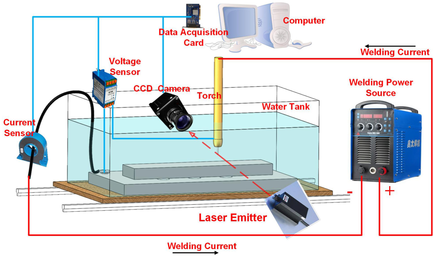
As shown in Figure 2, previously developed imaging system was used to capture the images of bubble and droplets transfer. 12 Note that two background light sources were employed in this article. A laser (808 nm, 30 W) was placed at the other side of the tank opposite to the camera. Thus, Figure 6 was captured using the laser as light source. Similarly, a dysprosium lamp with diameter about 0.5 m was used as another light source. The presented Figures 4, 9, and 10 were obtained in this way. The color images in Figure 11 were acquired using a color Charge Coupled Device Camera (CCD Camera) manufactured by Basler Electric Company (Basler acA2000-165uc USB 3.0, 165 fps, 2040 × 1086).
As shown in Figure 2, the high-speed camera (Optronis CamRecord 5000 × 2) worked at a frequency of 2000 fps, with a resolution of 512 × 512. Visual and electrical signals were collected synchronously. The water tank was placed on a platform to move linearly along the welding direction, and meanwhile, the torch was kept stationary (Figure 2).
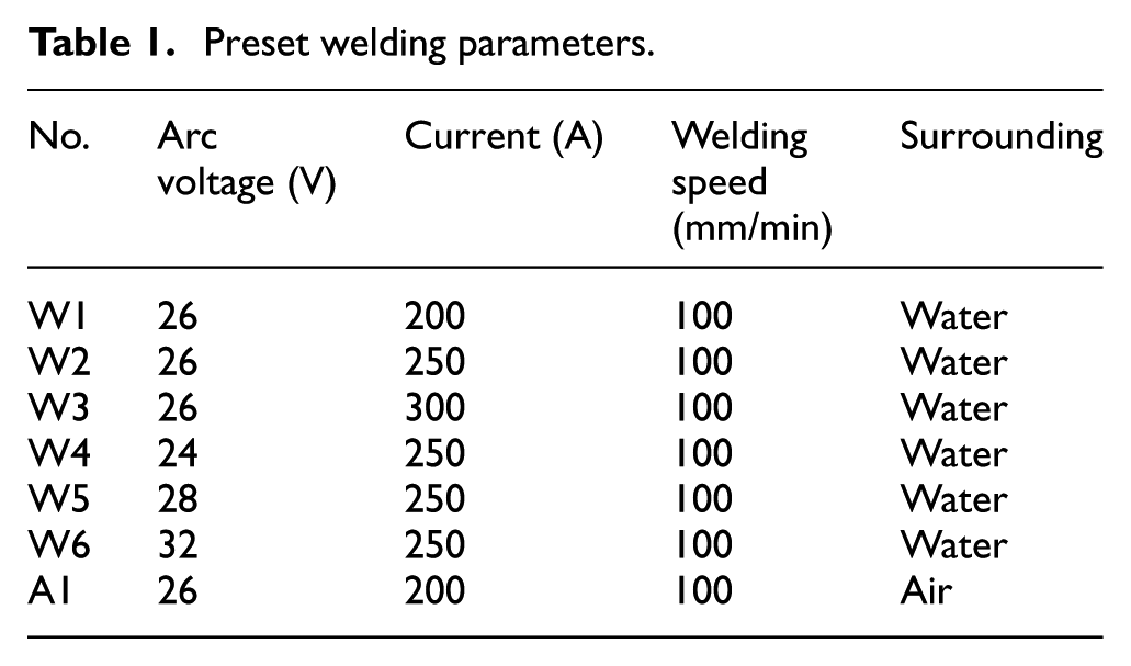
The shapes of bubble during underwater welding are changeable, especially under improper preset welding parameters. Taking these irregular and unstable bubbles into consideration makes it difficult for further analysis. To avoid this kind of trouble, experiments were carried out under selected preset welding parameters to assure the stability of welding process, that is, without long and frequent extinguishment. The welding conditions in this article were selected according to many experiments conducted by the authors. Investigations and analysis concerning the effect of preset welding parameters (arc voltage and current) on dynamic behaviors of bubble were conducted. Preset welding parameters were shown in Table 1.
Preset welding parameters.
Gas-assisted underwater FCAW (Figure 1) was proposed to improve the slag coverage and weld appearance. The flow (Ar, 99.99%) was transferred into the arc zone with the rate controlled by a gas regulator. The distance between the tip of the copper pipe and the substrate was about 15 mm, and the inner diameter of the copper pipe was 2 mm. As shown in Figure 3, several parameters were defined and introduced to describe the bubble (e.g. the minimum/maximum diameter, contact diameter, and height).
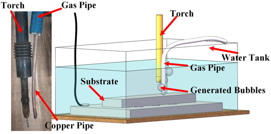
Schematic representation of the gas-assisted underwater FCAW.
Schematic representation of the underwater wet flux-cored arc welding imaging system.
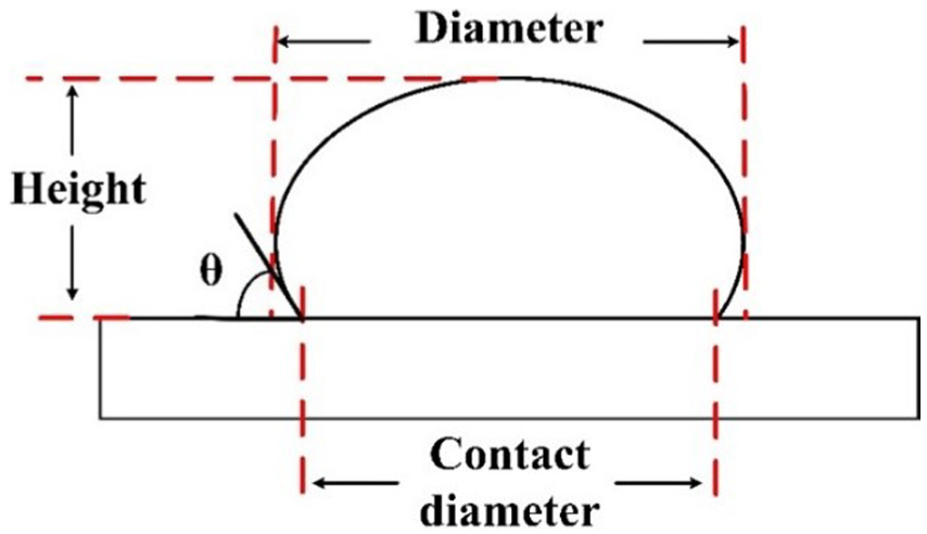
Parameters of a typical bubble.
Results and discussion
Classification of bubble generation modes
According to the authors’ experiments, it is almost impossible to totally eliminate the arc extinguishing during underwater welding. The ignition period and the extinguishment caused by surface tension transfer were typical unstable arc burning situations. Therefore, the bubble generation modes under selected preset welding parameters were classified into two types: bubble generated with a stable arc and an unstable arc. The role of arc burning during the bubble growth was investigated according to this classification.
Bubble generation with a stable arc
As shown in Figure 4, during the stable welding period, the bubble growth was rather regular. The bubbles in Figure 4 were obtained under 26 V and 300 A. The process can be roughly divided into two periods: expanding stage and detaching stage.
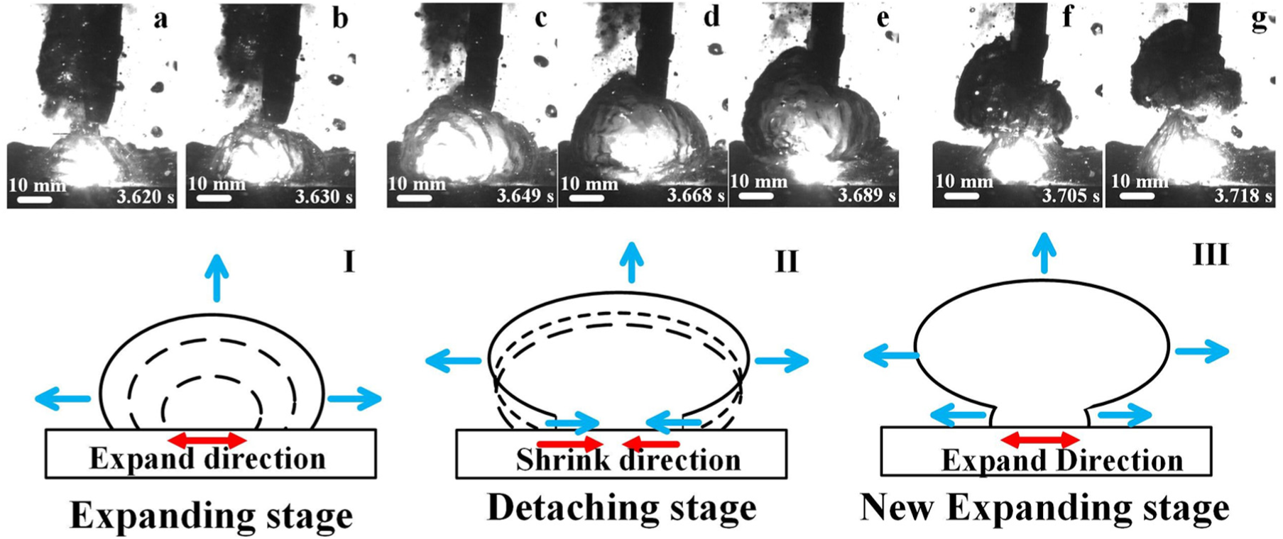
Typical bubble growth during stable wet welding (26 V, 300 A). (a, b, I) are during the bubble expanding stage (c, d, e, II) are during the bubble detaching stage (f, g, III) are during a new bubble expanding stage. The growth directions of bubbles were marked with arrows.
The directions of growth had been marked with arrows in Figure 4. The diameter and height of the bubble continued to grow after the generation. Its shape looked like a growing oval (Figure 4(a) and (b)). When the bubble grew to its maximum diameter which was about 40 mm (Figure 4(c)), the retention forces were transiently equal to the detaching forces. Consecutively generated gas flow increased the detaching forces acted on the bubble and broke the balance. The bubble floated upward. A neck formed at the bottom of the rising bubble making it looked like a mushroom (Figure 4(d) and (e)). Once the bubble begun to float, the motion directions of upper bubble and bottom bubble were not synchronous anymore. The lower bubble continued its shrinkage while the upper continued its rising (Figure 4(f)). After the upper bubble completely detached from the bottom bubble, pressure differences existed between its bottom and upper surfaces. The surface tension of this huge bubble was too small to keep its original shape. Therefore, the bottom of detached bubble rapidly bounced back to the core forming a temporary concavity (Figure 4(g)).
The waveform of current and voltage (Figure 5) indicated that this bubble generation process was rather stable. Therefore, this kind of bubble generation during stable arc burning can be considered as an idealistic bubble growth.
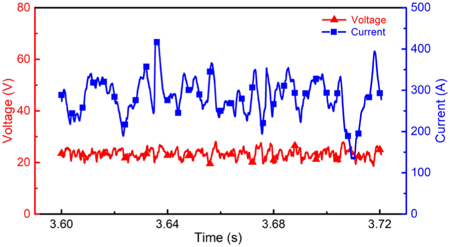
The waveform of welding current and arc voltage (26 V, 300 A).
Bubble generation without arc
A typical surface tension transfer process was provided to further clarify the role of arc during welding process. Before the droplet was transferred (Figure 6(b)), the arc had extinguished and the current also dropped to about 30 A (Figure 7). The volume of bubble reduced a lot and could barely enclose the droplet. 18 The arc zone was invaded by water due to the shrinkage. Once the droplet contacted with the weld pool (Figure 6(c)), the circuit was short-circuited. The current soared to 380 A (Figure 7), which accelerated the decomposition of flux core and vaporization of water immediately. The maximum diameter of the generated bubble was about 16 mm. After the transfer, the current dropped to 20 A sharply and no obvious arc could be observed. Both indicated the arc was not reignited. Without the arc burning or the heat provided by short-circuit current, the real-time flow generation rate dropped a lot. The bubble could not maintain its volume and finally broke into a succession of small bubbles (Figure 6(e)).
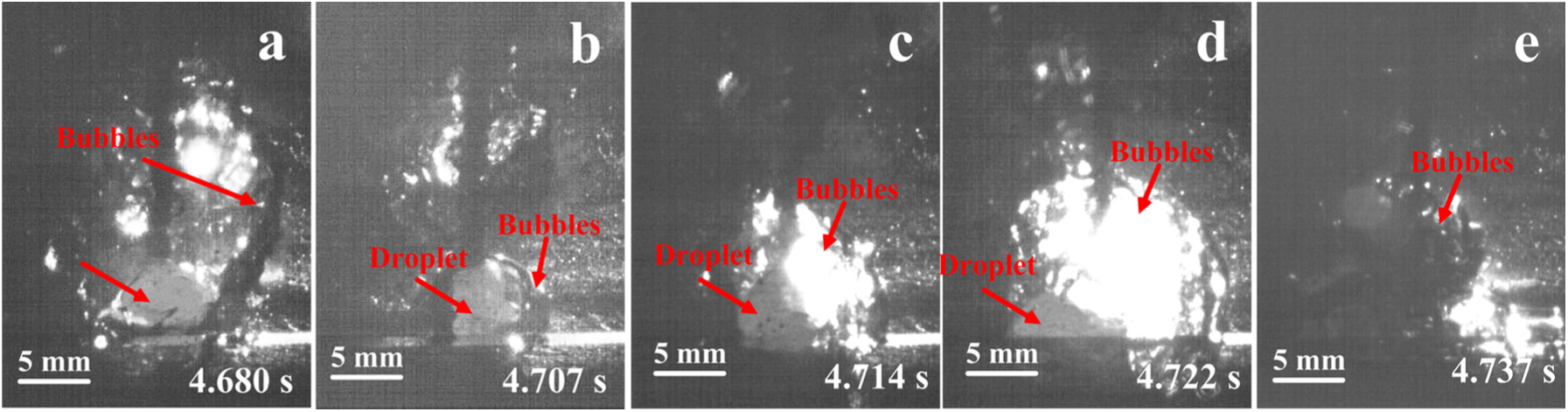
Bubble growth during surface tension transfer.
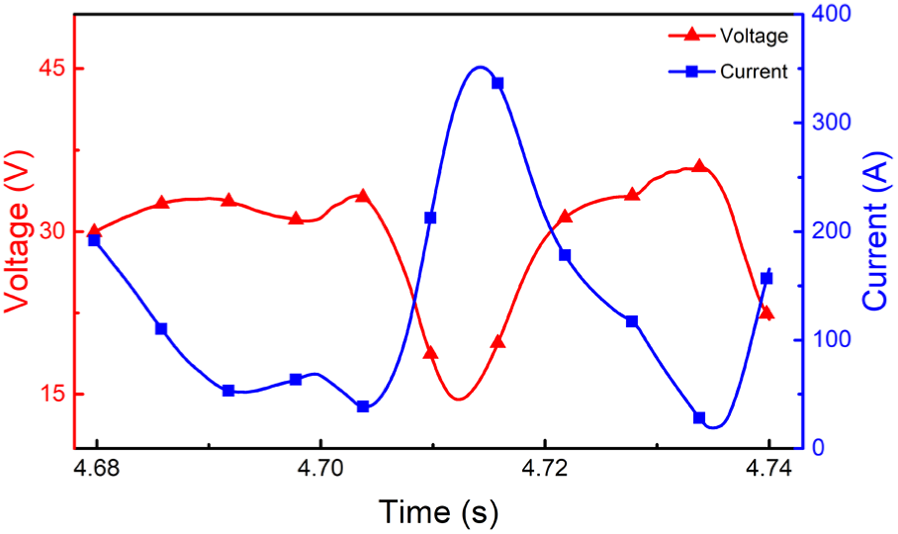
Dynamic characteristics of arc voltage and welding current during the surface tension transfer.
This was a typical bubble growth without arc. The diameter of maximum bubbles during this process was much smaller than the bubbles achieved during stable process. Considering the inconsecutive gas flow generation during unstable arc burning, it is reasonable to deduce that without the stable arc burning, long-lasting stable bubble growth around the arc zone cannot be achieved.
The arc extinguishment during this process was caused by droplet transfer. For traditional welding in the air, surface tension transfer can reduce the generation of spatters, 19 which makes it an idealistic transfer mode. However, for underwater welding, the stability of bubble growth and welding process are deteriorated by this transfer mode. Further investigations are still required to avoid this kind of transfer.
Bubble generation with repeatedly ignited arc
During the ignition period, once the wire contacted with the substrate, welding current increased sharply causing intense decomposition of flux core. Obtained images showed that the bubble equipped with the characteristics of explosive growth and rapidly increasing volume (Figure 9(b)). As the decomposition and vaporization continued under short-circuit current, the wire detached from the substrate. After the detachment, the arc was temporarily ignited but extinguished immediately. The circuit as well as the gas flow generation was interrupted due to the extinguishing. Therefore, the gas flow generation stopped and the bubble broke into small bubbles (Figure 9(d)). In a short time, continually fed wire contacted with the substrate and repeated the arc ignition process again. Oxides on the substrate surface were removed by the arc. 13 Finally, the arc was ignited and kept burning without extinguishment. The growth of bubble entered the stable period.
During this bubble stabilizing evolvement, the arc could not be successfully ignited in a single time. As can be observed from the electrical and visual signals (Figures 8 and 9), the ignition was carried out for four times. By contrast, in air environment, stable arc was established with two trials. The environmental difference mainly contributed to this arc continuity difference. The bubbles during the underwater stabilizing period were rather small (less than 10 mm). The ignited arc was close to the water surrounding and much more heat was transferred to the surrounding water. The temperature of surrounding was rather low and the gas ionization rate was limited. 20 Both made it difficult for the arc to burn stably.
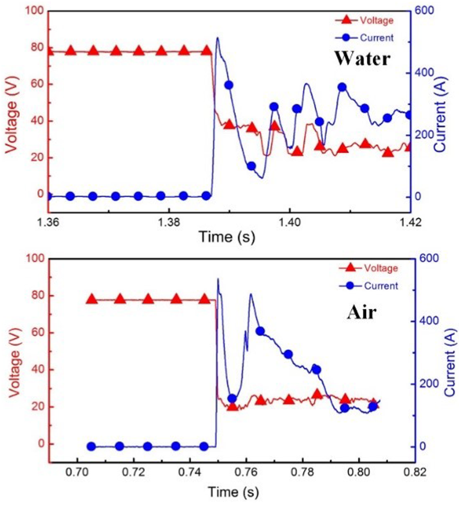
Electric signals during ignition in different environments under the same preset welding parameters (28 V, 250 A).
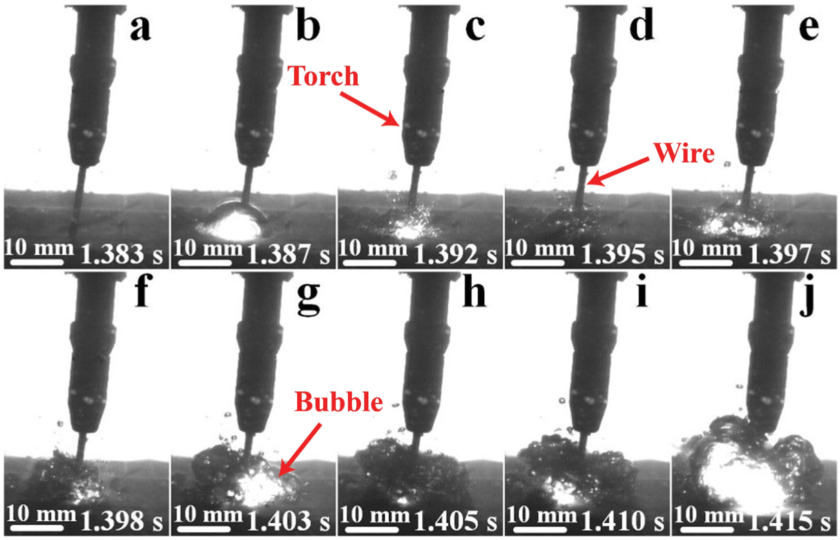
Bubble growth during ignition (28 V, 250 A). The torch, wire and bubbles were marked with arrows. (a) short circuit (b) arc ignition (c) bubble exploded (d) arc extinguishing (e) arc re-ignition (f) bubble exploded (g) more bubbles generated (h) disturbed and unstable arc (i) arc and bubble stabilization (j) stable arc and bubble.
The process of ignition (Figure 9) also showed that without a rather big and stable main bubble around the arc zone, even the arc was ignited successfully, it would distinguished quickly. Therefore, the authors proposed that the stability of arc burning and bubble generation relies on each other. The stability of underwater FCAW cannot be achieved without anyone.
Bubble behavior after detachment
The characteristics of bubble after detachment have been investigated. Previous researches rarely covered this period. An important characteristic of the bubble after detachment should be noticed. The volume of bubble floated up to the water surface as well as the occurrence of brilliant yellow–white flare burning at the surface decreased as the augment of water depth. Condensation of steam, and reaction of hydrogen and oxygen inner bubbles mainly contribute to this phenomenon.
The high temperature arc during underwater welding inevitably vaporizes water. However, due to its active instinct and great temperature gradient, generated steam was condensed into water during the course of upward floatation. Besides, there existed a certain amount of oxygen and hydrogen generated by decomposition of water. The temperature of gas flow inside the bubble was rather high, which is beneficial for the oxygen and hydrogen to react violently. Deeper water enabled the condensation and reactions to proceed more thoroughly. As a result, the volume of bubble floated up to the surface as well as the occurrence of brilliant yellow–white flare burning at the surface decreased along with the augment of water depth.
The image of bubbles during floatation was shown in Figure 10. The bubbles burst due to the torch disturbance and the fumes were then dispersed into the water. The decrease of bubble volume during the upward flotation can be figured out from Figure 11. The volume of bubbles floated up to the surface was rather smaller at deeper water, and corresponding water surface was rather tranquil compared with shallow water (Figure 11). According to Silva and Hazlett’s 9 observation, the flare burning on the water surface was brilliant yellow–white flare, which was different from previous research. The flame color of hydrogen achieved in the air would be interfered by the existence of N2, steam inner the atmosphere, and other flammable gases which finally changed the flare into yellow–white.
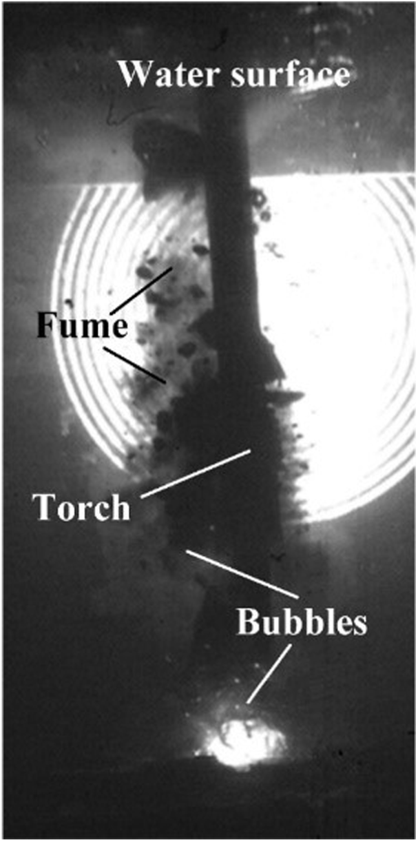
Bubbles floatation after detachment from welding area.
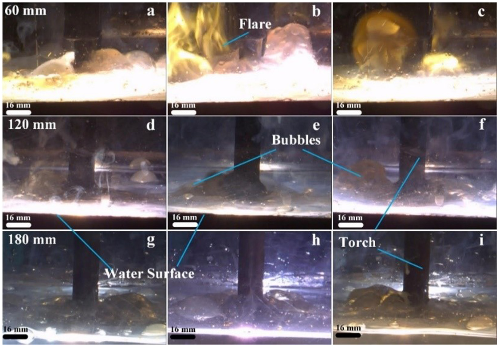
Different bubble behaviors when floating to the water surface at different water depths (32 V, 250 A). The flare, torch, bubbles and water surface have been marked with blue lines. (a, b, c) are at the depth of 60 mm (d, e, f) are at the depth of 120 mm (g, h, i) are at the depth of 120 mm.
Influences of preset welding parameters on bubble geometry
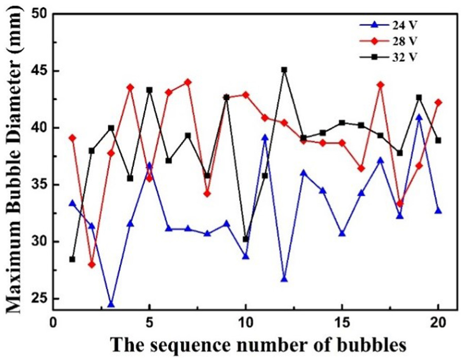
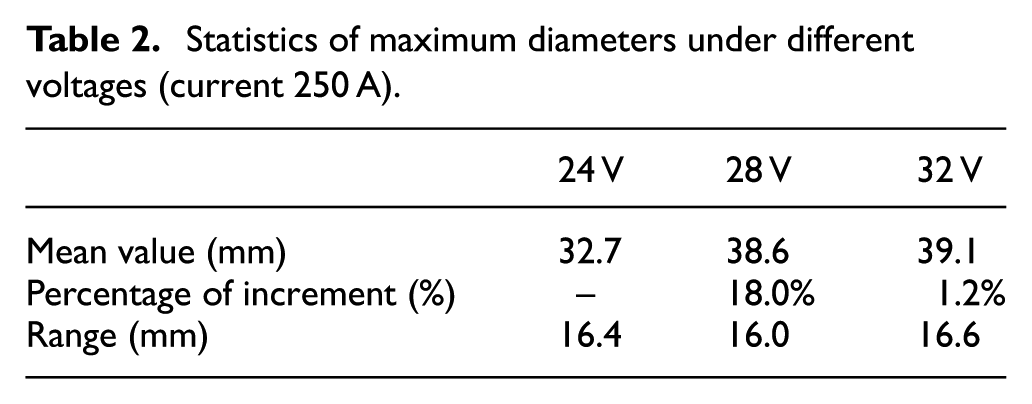
The maximum diameters of 20 consecutive bubbles during underwater welding were measured to reflect its geometry changes (Figures 12 and 13). These consecutive bubbles are generated at the period of stable welding process and no arc extinction happened during the process. The probability distribution of achieved diameters was calculated (Figures 14 and 15) and fitted with Gaussian fitting (equation (1)), for x represents the value of maximum bubble diameters and y represents the portion of these diameters. The range, mean value, and the increase of mean value were also calculated (Tables 2 and 3).
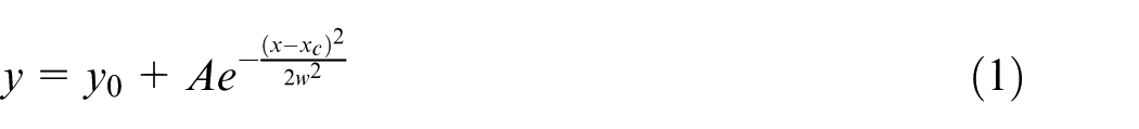
Maximum bubble diameters under different arc voltages (current 250 A).
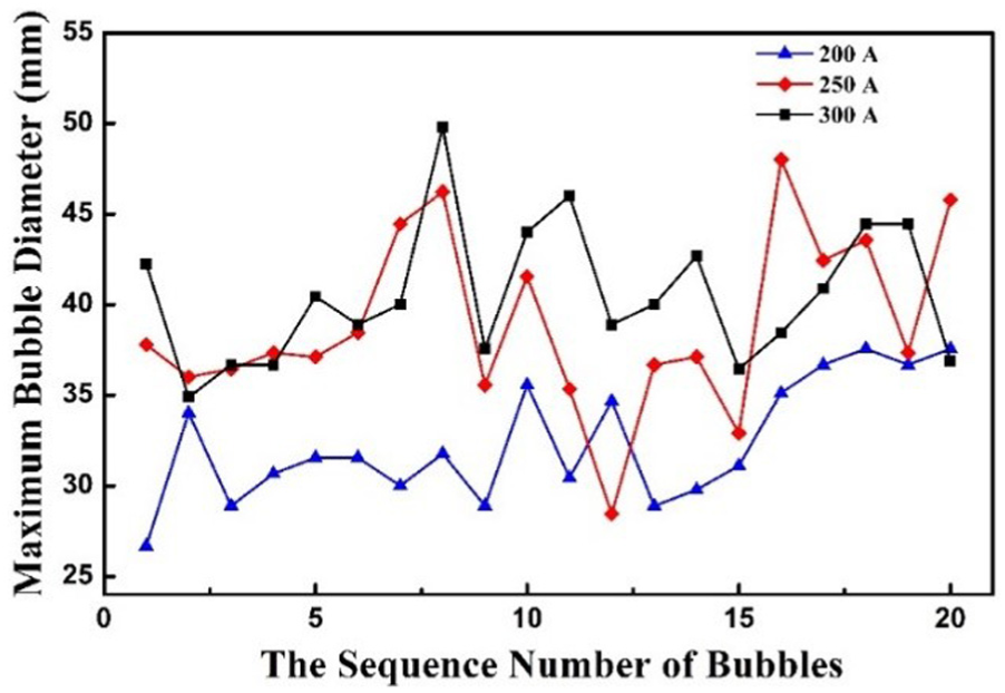
Probability distribution of maximum diameters under different voltages and corresponding fitted curves (current 250 A).
Maximum bubble diameters under different currents (arc voltage 26 V).
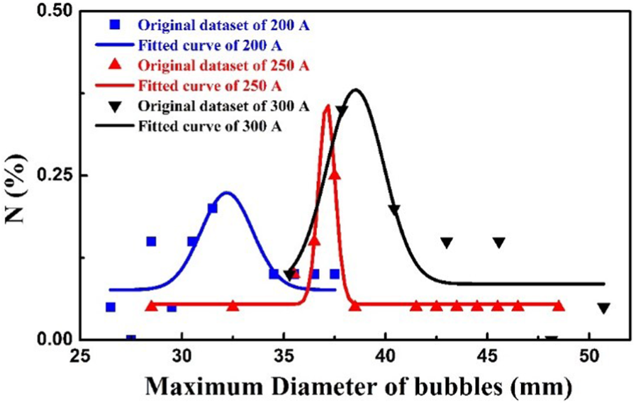
Probability distribution of maximum diameters under different currents and corresponding fitted curves (arc voltage 26 V).
Statistics of maximum diameters under different voltages (current 250 A).
Statistics of maximum diameters under different currents (arc voltage 26 V).
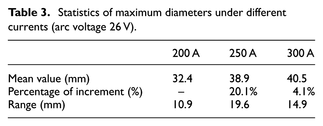
Although welding parameters were set in a narrow range to assure the stability of welding process, the maximum bubble diameters still fluctuate significantly (Tables 2 and 3). Preset welding parameters (current and arc voltage) have significant effects on bubble behaviors. Two noticeable characteristics can be drawn from the images (Figures 14 and 15). First, under the selected welding parameters, the diameters are not constant and show the characteristic of normal distribution. Second, under the selected welding parameters, elevating preset parameters increases the maximum bubble diameter but the increment rate decreases.
Previous research indicated that a larger and lower frequency bubble evolution is ideal and provides better protection to welding process. 11 However, according to the two characteristics mentioned above, for voltages higher than 28 V or current higher than 250 A, the increase of bubble volume brought about by elevating welding parameters is limited. Further elevating the welding parameters merely with the intension to achieve larger bubble is less meaningful. Besides, the way of elevating welding parameters to obtain larger bubble may not be practical enough at some special, harsh environment, and thus, methods should be proposed to achieve better bubble performance more actively.
Influences of generated bubbles on slag distribution
Two common characteristics about the beads obtained through normal underwater wet FCAW were observed. First, the slag coverage of underwater beads was poor (Figure 16) while bead obtained with the same wire in the air was satisfying (Figure 16(a)). Second, the underwater beads were characterized with many humps and the surface was not smooth enough. Without the protection of slag, the molten pool contacted with the water surrounding directly after it left the main bubbles. Measures should be done to overcome these problems. It is believed that the two characteristics have a strong correlation with the dynamic characteristics of bubble during underwater welding especially the size of bubble. Available research has proved that mechanical-constraint-assisted underwater wet welding can keep large bubbles around the arc zone and thus is effective in improving the weld appearance. 12 The author made an assumption that better protection provided by much bigger bubble could also alleviate the slag coverage problem. However, comparing the beads obtained at different currents, that is, at different size of bubbles, the slag coverage, and bead appearance, did not show much improvement. It was assumed that the bubble volume increase brought about by elevating welding parameters was still too small to achieve substantial difference.
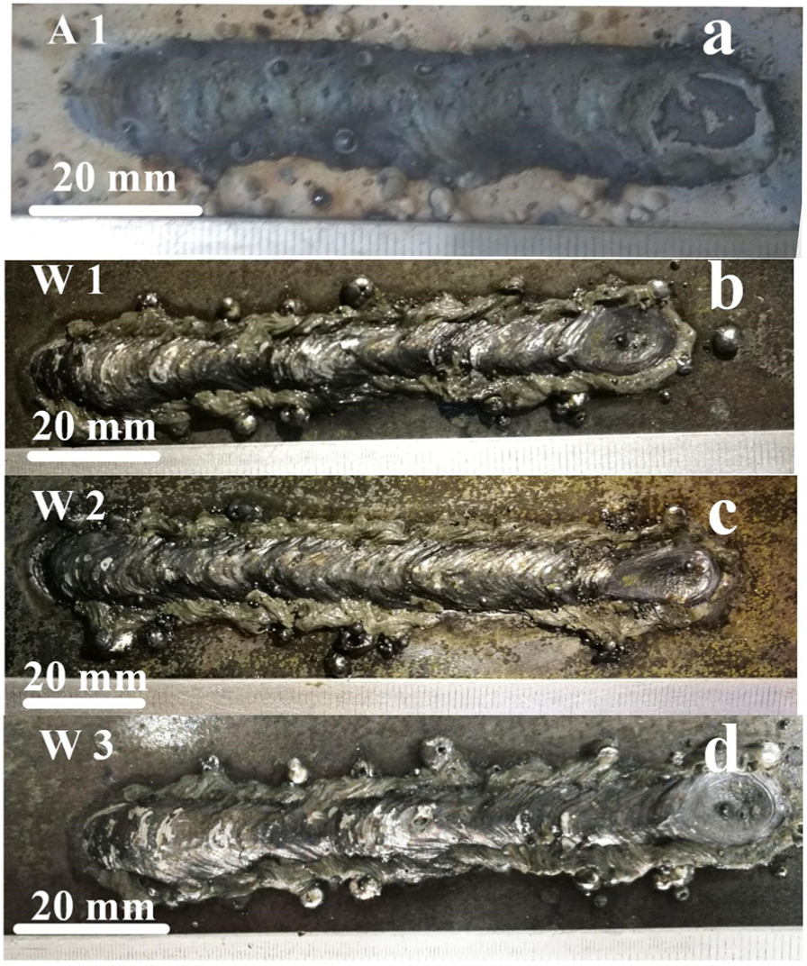
The slag distribution difference in different surroundings. The welding parameters of (a) A1, Test case 1 in air, (b) W1, Test case 1 in water, (c) W2, Test case 2 in water, (d) W3, Test case 3 in water were listed in Table 1.
Experiments were carried out to verify the assumption. The experimental system was shown in Figure 1. The argon was injected into the arc zone during welding process with the intention to provide more gas and further enlarge the volume of generated bubbles. The obtained weld was divided into three parts accordingly to its slag coverage situation (Figure 17(a)). The slag coverage improved a lot and almost the whole bead was covered by the slag. Unlike beads obtained with normal underwater welding, the bead achieved by gas-assisted FCAW was also much smoother and showed better appearance (Figure 17(b) and (c)). The generated bubbles during this process were shown in Figure 18. The maximum diameter of the generated bubbles was more than 80 mm, which is almost twice larger than the bubbles generated during normal underwater FCAW.
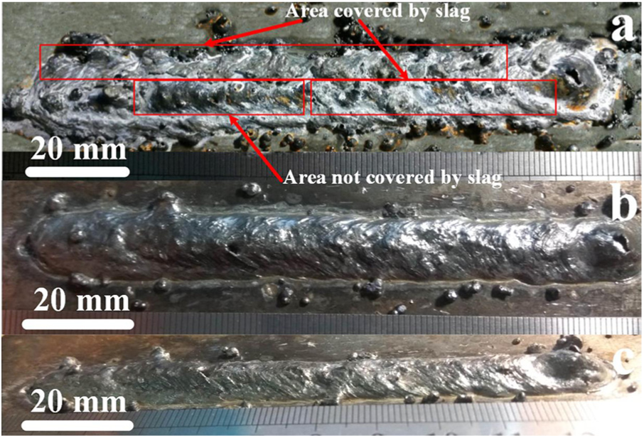
Improved bead with gas-assisted underwater FCAW. The three pictures are photo on the same bead with different angles (26 V, 300 A). (a) The slag was not removed. (b) and (c) The slag was removed.
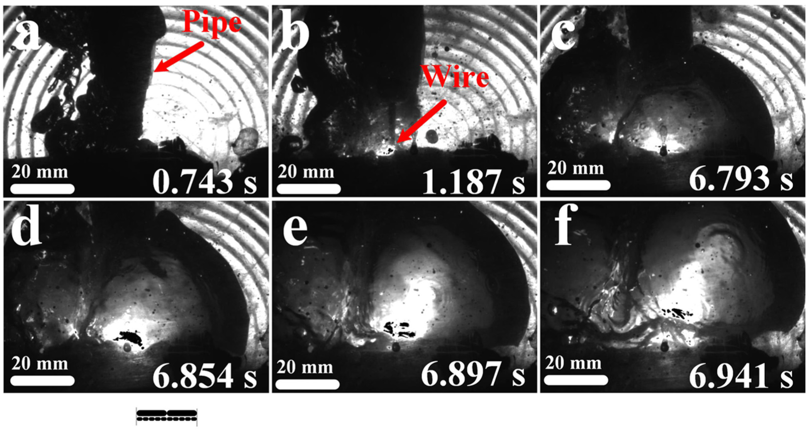
Generated bubbles during gas-assisted underwater FCAW (26 V, 300 A) (a) before arc ignition (b) arc ignition (c) rapid stabilized arc burning and bubble (d) expanding bubble and welding arc (e) arc length and bubble diameter increased (f) More stable arc burning and bubble.
Larger bubbles enable the molten pool to stay in the bubbles longer. With longer duration in the main bubbles, the slag has enough time to cover the bead and solidify to some degree. The more the slag has solidified, the less likely it will be dragged away from the bead after leaving the main bubbles. With better slag coverage, the bead is separated from the surrounding water even after it leaves the main bubbles. As a result, the bead was formed under the protection of covered slag rather than contacting with the water directly. Generally, the gas-assisted FCAW is effective in obtaining welds with better appearance. More experiments are still needed to further improve this method and provide a guidance in developing underwater wet welding process.
Conclusion
Dynamic characteristics of bubbles under different conditions produced in underwater welding were investigated through experiments and discussions. Main conclusions are summarized as follows:
Two bubble growth modes under selected welding parameters were observed and their characteristics were summarized. To improve the stability of arc burning, measures should be taken to avoid the surface tension transfer.
The stability of bubble growth and arc burning relied on each other. Without the arc, molten droplets and weld pool could only produce bubbles temporally with sharply shrank volumes. Without stable bubbles, ignited arc would extinguish quickly.
Under selected welding parameters, the maximum bubble diameters of the same welding parameters were in normal distribution. Elevating preset welding parameters can generate larger bubbles, however, this effect is limited.
When bubbles floated up to water surface, the residual hydrogen and other flammable gases burned with yellow–white flares. Due to the intense steam condensation and reactions of gases, the volume of floating bubbles shrinked quickly.
The gas-assisted underwater FCAW can achieve much larger bubbles and is effective in achieving beads with better slag coverage and better appearance.
Footnotes
Declaration of conflicting interests
The author(s) declared no potential conflicts of interest with respect to the research, authorship, and/or publication of this article.
Funding
The author(s) disclosed receipt of the following financial support for the research, authorship, and/or publication of this article: The authors are grateful to the financial support for this project from the National Natural Science Foundation of China (Grant Nos. 51675310, 51105237) and the Fundamental Research Funds of Shandong University (No. 2015TB002).