
Abstract
The machining of high precision gears requires a strict and accurate co-movement relationship controlled by the electronic gearbox between the moving axes of the gear machine tools. This article proposes a tooth surface contour error modeling method and an adaptive electronic gearbox cross-coupling controller for internal gearing power honing. First, the electronic gearbox model is structured according to the generative machining principle of internal gearing power honing and the tooth surface contour error is established by means of homogeneous coordinate transformation and meshing principle. Then, the adaptive electronic gearbox cross-coupling controller is designed, which comprises the electronic gearbox cross-coupling controller and the fuzzy proportional–integral–derivative controllers whose universes of membership functions in fuzzy rules are optimized by particle swarm optimization to improve the adaptability and robustness to disturbance fluctuation and model uncertainty of the system. Finally, experiments are carried out on a self-developed gear numerical control system. The results have demonstrated that the estimated tooth surface contour error using the proposed method is very close to the actual one, and the proposed adaptive electronic gearbox cross-coupling controller can effectively reduce the tracking error and the tooth surface contour error when compared to the electronic gearbox cross-coupling controller and non–electronic gearbox cross-coupling controller (electronic gearbox controller without cross-coupling and adaptive compensation).
Keywords
Introduction
In the gear finishing process, gear honing process is used to eliminate the errors after rough machining and heat treatment because of its high efficiency, economy and easy adjustment of involute profile.1,2 Compared with external gear honing, internal gearing power honing has many advantages, such as large degree of overlap ratio, small relative velocity of contact point, relatively uniform contact area and better modification effect. In internal gearing power honing, the honing wheel and the workpiece gear mesh with each other according to a certain transmission ratio and crossed axis angle, which are known as “electronic gearbox” (EGB). Similar to the definition of contour error, the tooth surface contour error of EGB for gear machining is defined as the normal deviation between the ideal tooth surface and the actual tooth surface. In order to improve the machining precision, the modeling and compensation of tooth surface contour error for internal gearing power honing is an urgent problem.
The principle of gear meshing is the basic method for analyzing the machining errors of gears. Litvin and Fuentes 3 and Dudley 4 made a detailed analysis of the gear meshing principle, gear machining and tooth contact in their textbook. Based on the principle of milling and the theory of gear meshing, Wang et al. 5 put forward a high-efficiency and high precision machining method of spur face gear. Han et al. 6 and Tian et al. 7 proposed an embedded reconfigurable EGB platform which contains parametric programming and process database module and verified the correctness and effectiveness of the platform on a six-axis gear hobbing machine. Some classical error modeling methods for machine tool processing, such as Denavit–Hartenberg (D-H), rigid body kinematics, homogeneous transformation matrix (HTM) and screw theory, have been developed in previous research works.8–10 Fang et al. 11 established the model of tooth profile deviation, helix deviation and cumulative pitch deviation using HTM via changing gear eccentricity error, gear inclination error and gear resultant error. Chen et al. 12 established a comprehensive error model of six-axis computer numerical control (CNC) spiral bevel gear grinding machine by utilizing the multi-body system theory and HTM. The modeling and compensation method for systematic geometric errors were proposed to improve the machining accuracy of multi-axis machine tools. 13 By means of homogeneous coordinate transformation, Wu and Tran, 14 Shih and Chen15,16 and Fong and Chen 17 constructed the mathematical model of gear machining process and proposed effective and feasible tooth flank topographical modification methods for external gear honing and form grinding. In order to improve the tooth surface quality and accuracy of gear honing, Da Silva et al. 18 used particle swarm optimization (PSO) algorithm to select the appropriate process parameters. However, in the process of machining, the movement error of the machine tool has a great influence on the geometric accuracy of the workpiece. With the error model of workpiece, the design of appropriate controller and the compensation for movement error can greatly enhance the machining accuracy.
Error compensation of the servo control system, also including the EGB, is generally divided into two strategies, one is to reduce the tracking error by improving tracking performance of individual axis, 19 and the other one is to use the control algorithm to reduce the contour error directly, such as cross-coupling control 20 and task coordinate frame control method. 21
In order to improve the performance of individual axis tracking, many scholars have proposed a lot of effective tracking error control methods, such as feedforward control, friction compensation and intelligent control algorithms. On the basis of perfect tracking controller (PTC), a zero phase tracking controller is proposed by Tomizuka. 22 The method performs inverse process to the closed-loop dynamic system in a wide bandwidth range and is sensitive to the change of the transfer function of the system. Han and Lee 23 proposed an output-tracking-error-constrained dynamic surface control (DSC) for the robust output positioning of a multiple-input–multiple-output nonlinear dynamic system in the presence of friction, dead-zone, non-smoothness and non-linearity. Based on variable switching gain and adjustable boundary layer, Zhao et al. 24 proposed a novel adaptive sliding mode controller for five-axis CNC machine tools, considering the nonlinear friction and the interference of cutting force.
However, only improving the tracking accuracy of individual axis alone cannot improve the contour accuracy very well. Koren 25 presented a cross-coupling controller (CCC) for biaxial system, which can reduce the influences of interference and axis mismatch on the contouring control performance, while the speed response is not deteriorated. Yang and Altintas 26 presented an efficient and easy to implement approach for the online estimation and control of five-axis contouring errors in the case of nonlinear and configuration-related kinematics. Du et al. 27 proposed a third-order estimation method of the chord error to improve the estimation accuracy of the evaluation index of machining accuracy, using a conical helices that has third-order contact with the freeform curve. Based on rigid body theory and the error data measured by laser interferometer, Pezeshki and Arezoo 28 proposed an accurate kinematic error estimation model and developed a software package that can integrate kinematic errors and NC codes. Moreover, combining with an estimation method of the helical gear pitch error and the spiral line contour error, Tian et al. 29 proposed an electronic gearbox cross-coupling controller (ECCC) structure, which consists of the EGB and the CCC. In order to reduce the influence of disturbances such as friction, load fluctuation and uncertainty of axis characteristics on contour accuracy, many scholars have proposed adaptive contour control methods for multi-axis motion. Lee et al. 30 presented a standard adaptive nonlinear control method that is applied in the transformed cross-coupled machine dynamics to compensate for uncertain inertial and friction parameters. To improve the motional smoothness and contour precision of CNC machine tools, Zhang et al. 31 developed an adaptive control method based on parametric predictive model and variable universe fuzzy control. In order to enhance the robustness and capacity to resist disturbance, Liu et al. 32 proposed an improved method for pre-compensation of contour error through an adaptive cross-coupled prediction compensation controller (ACPCC).
However, there is insufficient research to demonstrate whether the above strategy can be used in the EGB. Some special linkage relationships are included in the gear generating process, and the coupling motions between the honing wheel rotating axis, the workpiece gear rotating axis and the optional axial feed are constrained by the EGB. The accuracy of gear honing not only depends on the contour accuracy of the tool path but also depends on the synchronization accuracy between the honing wheel and the workpiece gear.
In this article, to reduce the influence of load fluctuation and model uncertainty on the control performance of the system, the tooth surface contour error model and an adaptive electronic gearbox cross-coupling controller (AECCC) are constructed for internal gearing power honing. First, an EGB model and tooth surface contour error model for internal gearing power honing are established by means of homogeneous coordinate transformation and meshing principle. Then, the AECCC consisting of ECCC and fuzzy proportional–integral–derivative (PID) controllers is proposed in which the universes of membership functions in fuzzy rules are optimized by PSO to improve the robustness of the system. Finally, simulation and experiment are used to verify the correctness and effectiveness of the proposed error model and AECCC. The results show that the proposed method can effectively improve the machining accuracy of internal gearing power honing.
The structure of this article is as follows. The analysis and modeling of tooth surface contour error are put forward in section “Analysis and modeling of tooth surface contour error for internal gearing power honing.” The AECCC is structured in section “Particle swarm optimization fuzzy EGB cross-coupling.” Section “Simulation and experiment” presents a comparison of the simulated and experimental results. Finally, the article is concluded in section “Conclusion.”
Analysis and modeling of tooth surface contour error for internal gearing power honing
EGB of internal gearing power honing
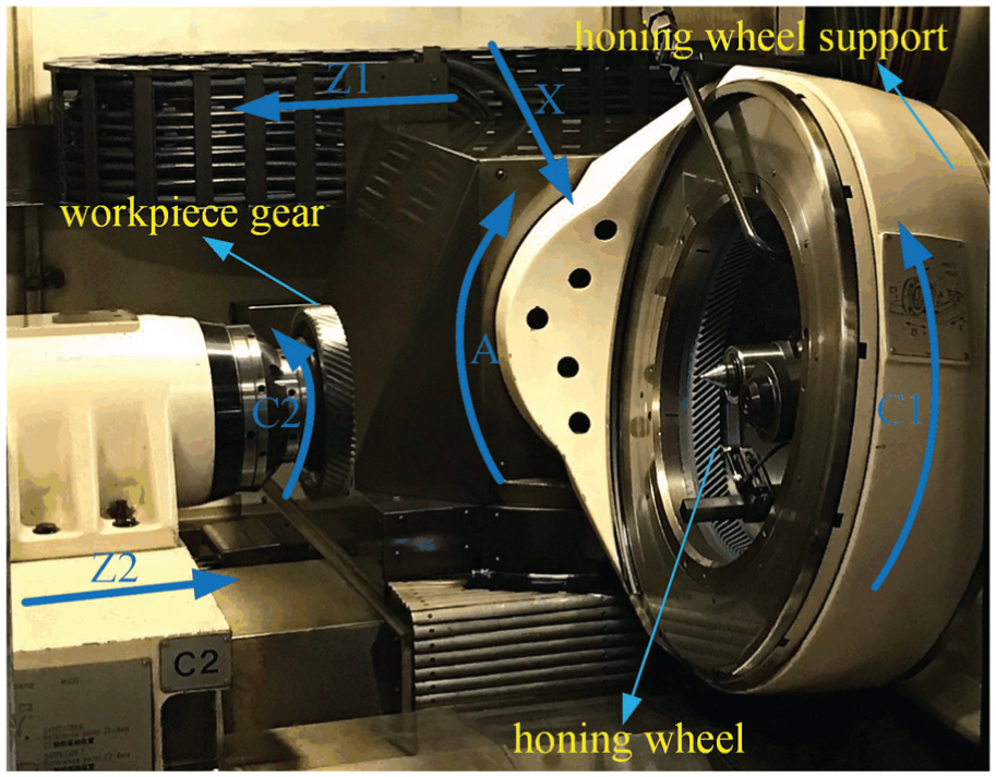
As shown in Figure 1, an emblematical internal gearing power honing machine (e.g. Fässler HMX-400) which is used to generating machine helical gears is provided with seven CNC axes: the axial feed Z1 in dressing process and honing process which is parallel to the rotation axis of workpiece gear, the rapid feed Z2 of headstock carrying the workpiece gear spindle, the radial feed X of the honing wheel toward the workpiece gear or dressing tool, the rotation axis C2 of workpiece gear or dressing tool, the swivel rotation A of honing wheel for axis crossing angle, the swivel rotation B of honing wheel head for longitudinal crowning and tapering, and the rotation axis C1 of honing wheel. When honing cylindrical helical gears using the method of incremental infeed, there are three axes involved in linkage: the C1-axis, the C2-axis and the Z1-axis. The A-axis is used to adjust the crossed angle Σ (as shown in Figure 2) between the honing wheel and workpiece gear which is a fixed machine-tool setting during the honing process. The gear honing is equivalent to a pair of staggered axis helical gears, one of which is viewed as a honing wheel, and the other gear is treated as a workpiece gear. The synchronous motion between the workpiece spindle and the tool spindle is realized by using an EGB module embedded in a self-developed CNC system. After the EGB is opened, the C2 axis follows the position of the C1 axis for synchronized movement. The honing wheel gradually cuts the remainder of the tooth depth along the X-axis direction and then moves along the Z1-axis direction to remove the entire tooth width, while the X-axis remains unchanged. The mathematical model of the EGB can be represented by equation (1)
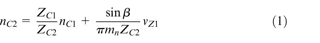
where
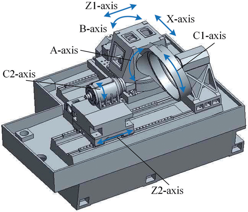
The structure and the definition of axis of an internal gearing power honing machine.
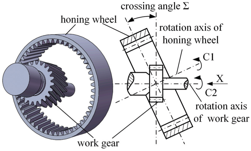
Internal gearing power honing kinematic schematic.
Tooth surface contour error model of internal gearing power honing
The diagrammatic sketch of coordinate transformation for gear honing is shown in Figure 3, in which coordinate systems

where
where
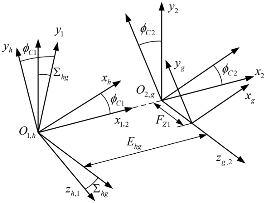
Diagrammatic sketch of coordinate transformation for gear honing.
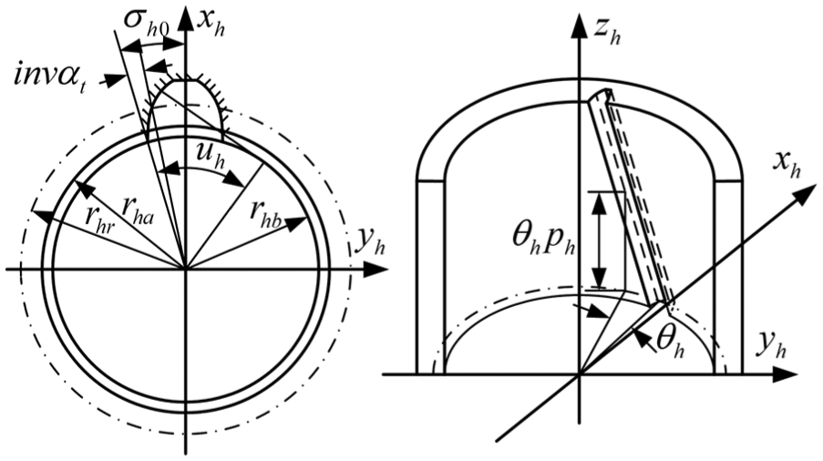
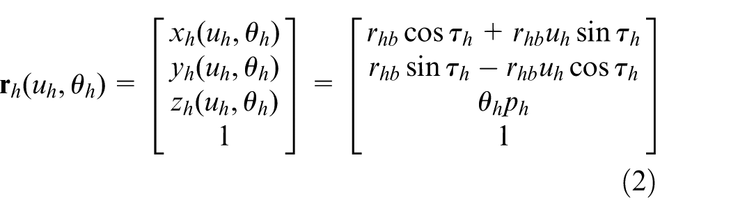
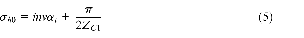
Tooth profile and surface parameters of honing wheel.
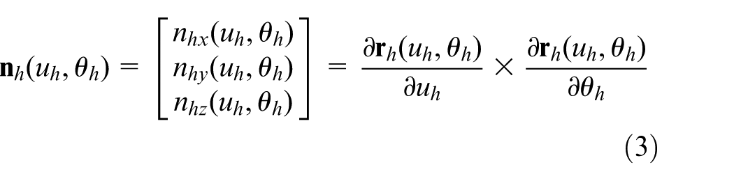
By applying the homogeneous coordinate transformation matrix equation, the position vector and normal vector of the workpiece gear’s tooth surface represented in coordinate system
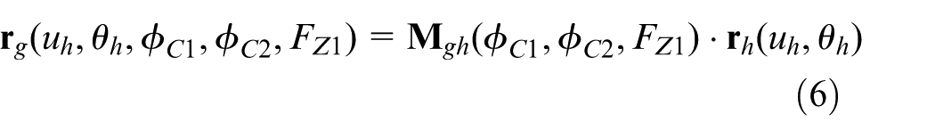
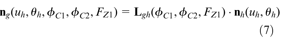
in which

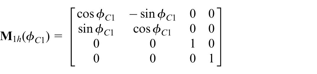
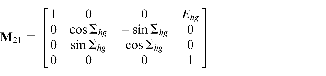
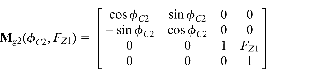
where
Since the gear honing process has two initiative movements,
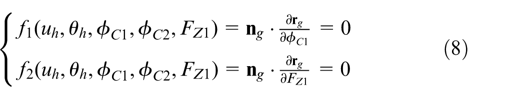
The position vector and normal vector of workpiece gear’s tooth surface are defined by considering equations (1)–(3), (6)–(8), simultaneously.
As shown in Figure 5, the tooth surface contour error
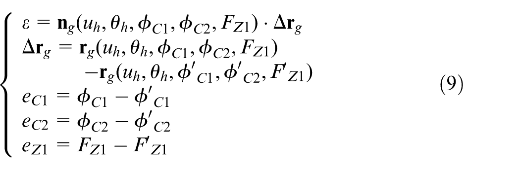
where

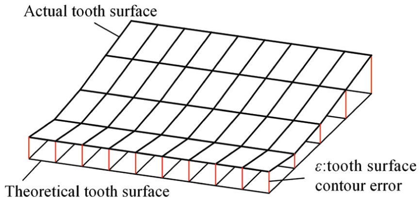
Tooth surface contour error of workpiece gear.
Particle swarm optimization fuzzy EGB cross-coupling
The movement of internal gearing power honing process is composed of C1-axis, C2-axis and Z1-axis. The machining error of the workpiece gear is not only related to the tracking error of each axis but also related to the coupling motion between those axes. Because the accurate dynamic model of the controlled object is not easy to obtain, and there are many interferences in the process of motion, the modern control algorithm must obtain high precision contour control in the case of disturbance and model uncertainty. In this section, an EGB cross-coupling control algorithm combined with PSO fuzzy controller has been proposed to improve the adaptability and robustness of the control system to disturbance and model uncertainty.
Design of ECCC
The cross-coupled controller for EGB system is shown in Figure 6.


where
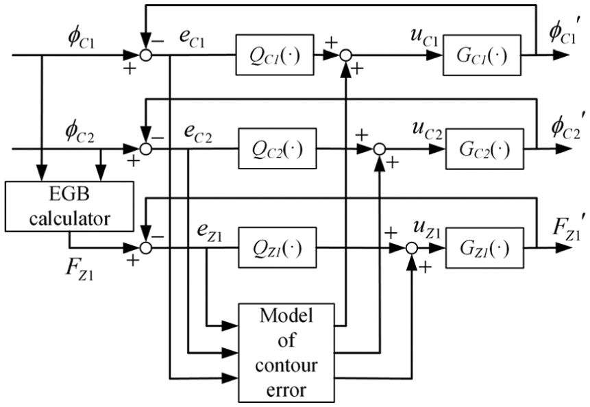
Cross-coupled controller for EGB system.
Adaptive EGB cross-coupling control algorithm.
The mathematical models of some practical systems that contain nonlinear components cannot be accurately expressed. Fuzzy logic control has been proved to be one of the most effective and systematic methods for dealing with such problems, whose control performance comes from the simulation of human logic rather than the precise mathematical model. Fuzzy PID can improve the adaptability and robustness of the control system to interference and model uncertainty by adjusting the PID parameters in real time, but the initial PID parameters and the fuzzy membership function have great influences on control performance. So this section proposes a method to optimize the initial PID parameters and the fuzzy membership function domain of fuzzy PID using PSO.
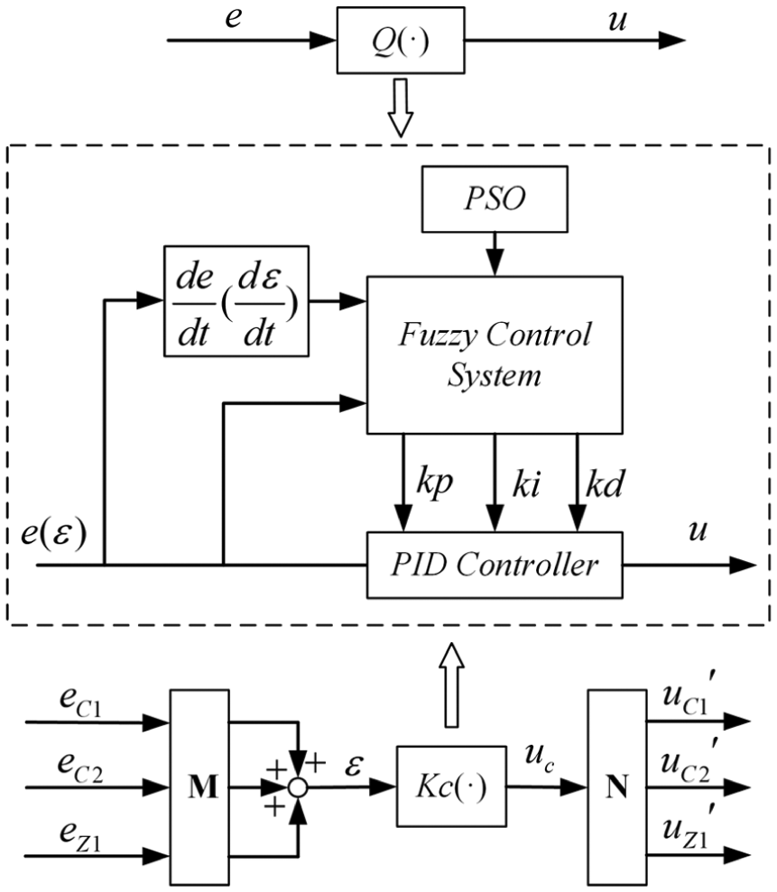
PSO-optimized fuzzy PID controller
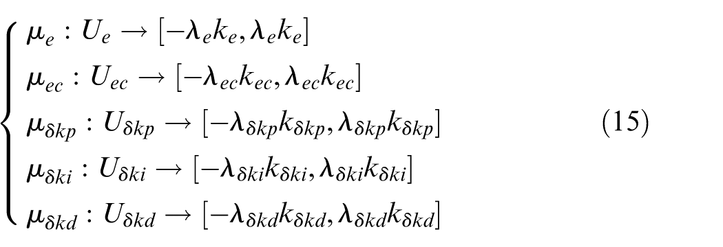
The flow-process diagram of PSO-optimized fuzzy PID controller is shown in Figure 8. A fuzzy controller with two inputs and three outputs is employed, in which error e and differential error ec constitute the two-dimensional inputs, and
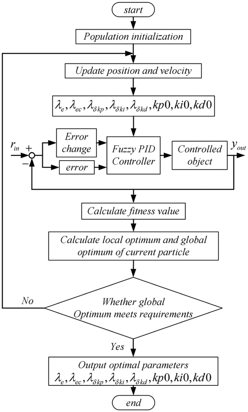
Flow-process diagram of PSO-optimized fuzzy PID controller.
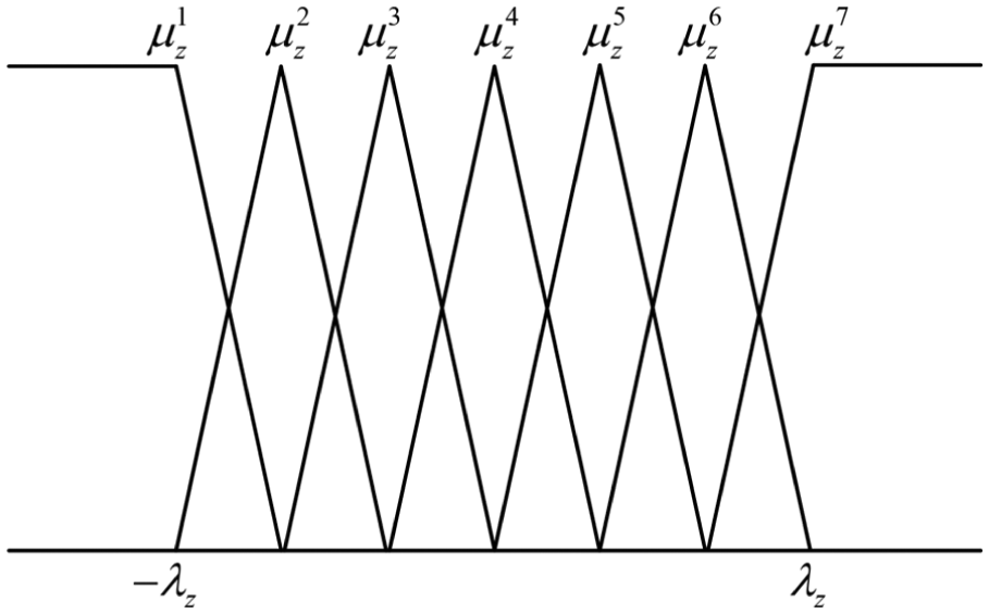
Membership functions for e, ec δkp, δki and δkd.
Suppose that in a D-dimensional target search space (D = 8 in this article), there are N particles forming a colony in which the ith (
The “flying” speed of the ith particle is also a vector of the D-dimension, denoted as
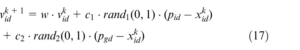

where
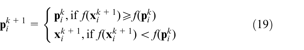
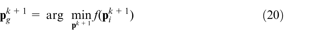
The local optimal position of the ith particle and the global optimal position of the population are updated by the following equations
Stability analysis
The output u(t) of the PID controller is depicted by the following equation
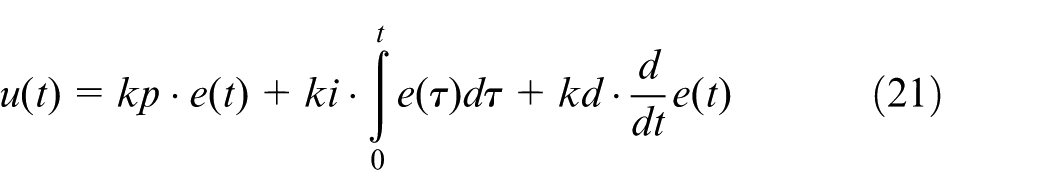
By using the backward difference method, the discrete form of u(t) is defined by equation (22). The incremental output
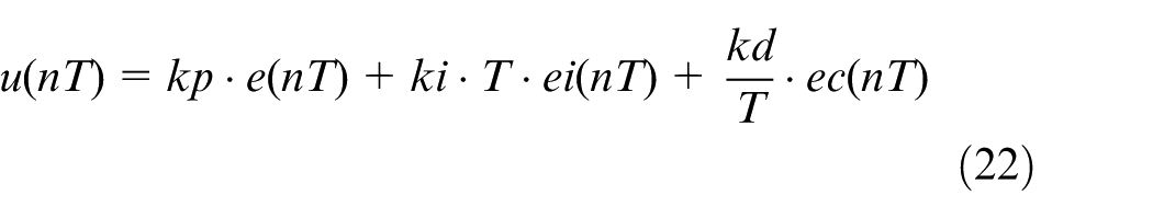
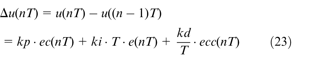
where
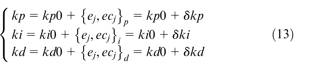
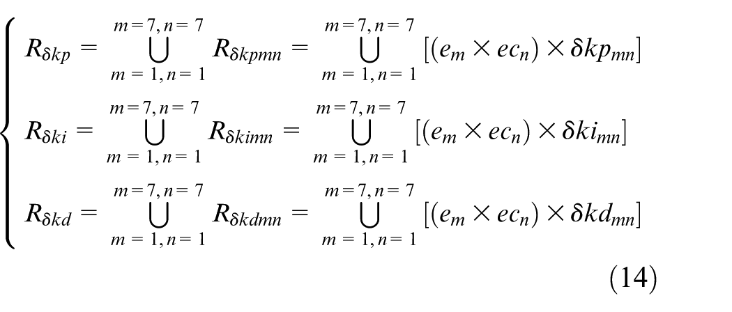
The main process of fuzzy PID controller consists of fuzzification, fuzzy inference and defuzzification. Let N be the number of fuzzy rules and
If
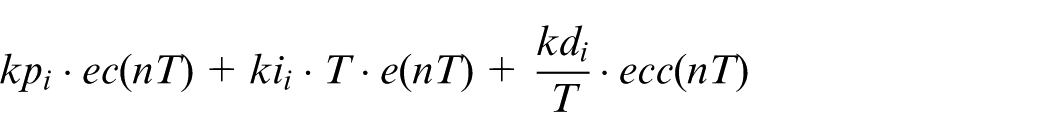
where
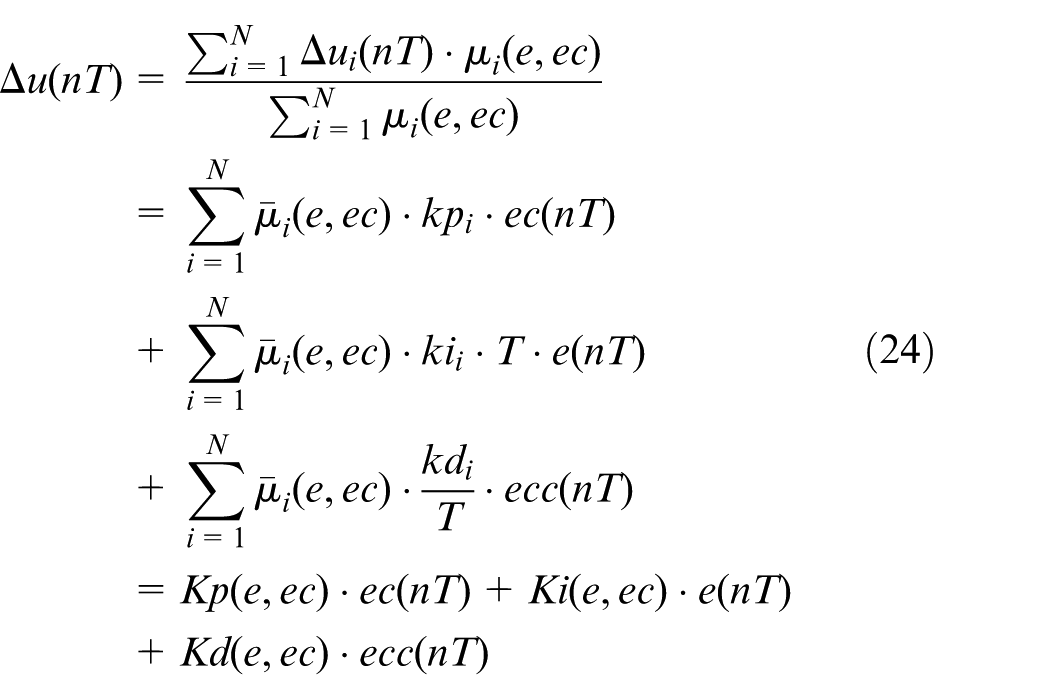
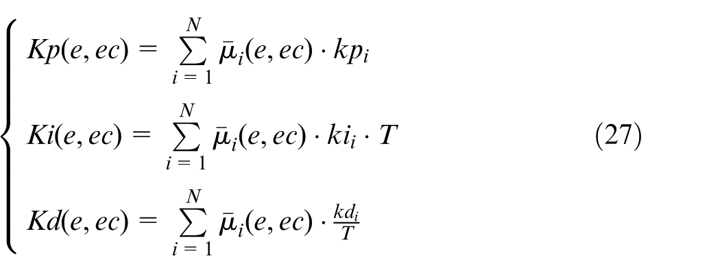
where
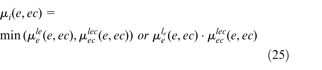
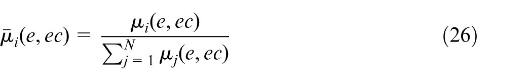
and kp(e, ec), ki(e, ec) and kd(e, ec) are the representatives of
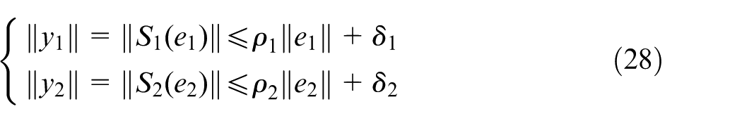
In this article, the small gain theorem is used to analyze the stability of the fuzzy PID controller. Consider a nonlinear feedback control system that contains two subsystems S1 and S2 shown in Figure 10. Assume that there exists four nonnegative constants
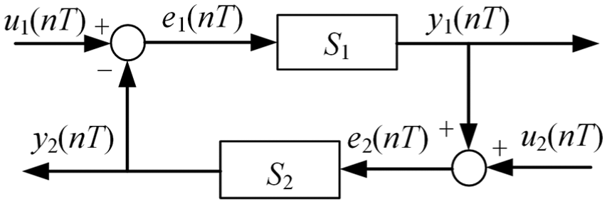
Nonlinear feedback control system.
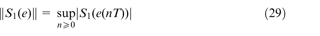
The norm of the output for the fuzzy PID control is defined as in equation (29)
Because
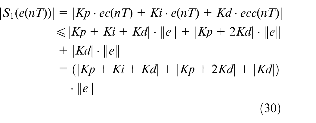
Then
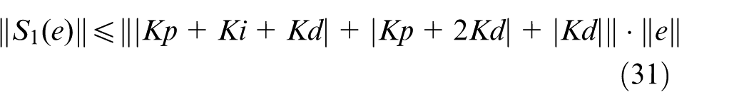
By substituting equation (27) into equation (31), equation (32) can be obtained under the conditions of
Assume that
and
The finite gain ρ2 of the subsystem S2 is supposed to be known. Accordingly, the sufficient condition for the fuzzy PID control system to become stable is then given by equation (35)
Simulation and experiment
Modeling of tooth surface contour error
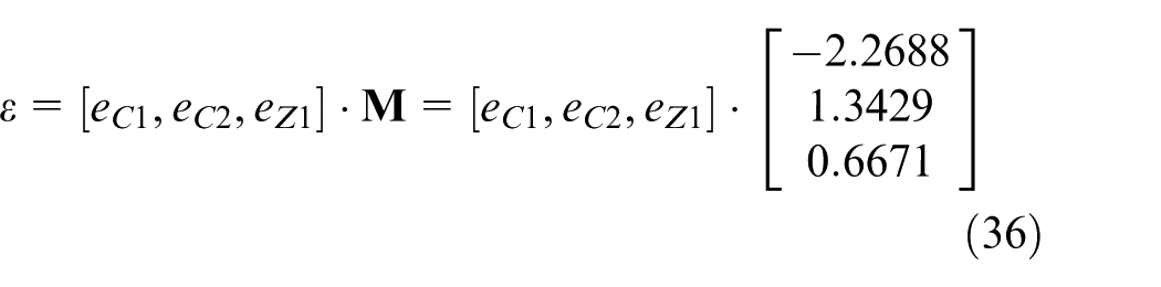
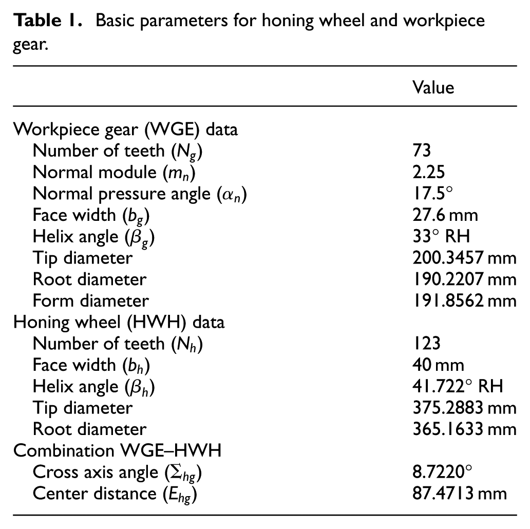
A helical gear is used as the honed gear to establish the tooth surface contour error and the basic parameters for honing wheel and workpiece gear are shown in Table 1. When C1-axis, C2-axis and Z1-axis have tracking errors, respectively, the tooth surface contour error calculated according to section “Analysis and modeling of tooth surface contour error for internal gearing power honing” is shown in Figure 11. It can be seen that the tooth surface contour error is proportional to the tracking error of each axis, which can be expressed as in equation (36)
Basic parameters for honing wheel and workpiece gear.
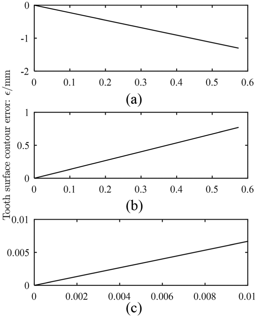
Tooth surface contour error of the honed gear with tracking error of C1-axis, C2-axis and Z1-axis: (a) C1-axis tracking error: eC1 (°), (b) C2-axis tracking error: eC2 (°) and (c) Z1-axis tracking error: eZ1 (mm).
The helical gears listed in Table 1 are machined on the internal gearing power honing machine Fässler HMX-400 shown in Figure 12. Then the correctness of equation (36) is verified by using the gear measuring center Klingelnberg-P40 shown in Figure 13. The incremental infeed of honing process shown in Figure 14 is adopted, where the oscillation of Z1-axis (cutting depth is 0) can effectively improve the surface quality. The oscillation speed of Z1 axis is 200 mm/min, the speed of C1 axis is 1000 r/min and the speed of the C2 axis calculated by the EGB is 1685 r/min. The results of the tooth surface measurement are shown in Figure 15, in which the tooth surface is sampled by 2 × 5 × 10 grid points and the width of the measured tooth surface is 20 mm. The machining errors data of the middle helix of the right flank are collected to verify the correctness of the tooth surface contour error model. The tracking errors of each axis are shown in Figure 16(a)–(c). Tooth surface contour errors calculated by equation (36) are shown in Figure 16(d). The comparison of measurement and estimation results of tooth surface contour error is shown in Figure 17. The measurement result is taken as the middle helix of the right flank and the estimated result is the average fitting value of the calculated tooth surface contour error. It can be seen that the estimation of tooth surface contour error is very close to the measured value, so the method of error modeling proposed in this article can be used to estimate the true value.
Internal gearing power honing machine Fässler HMX-400.
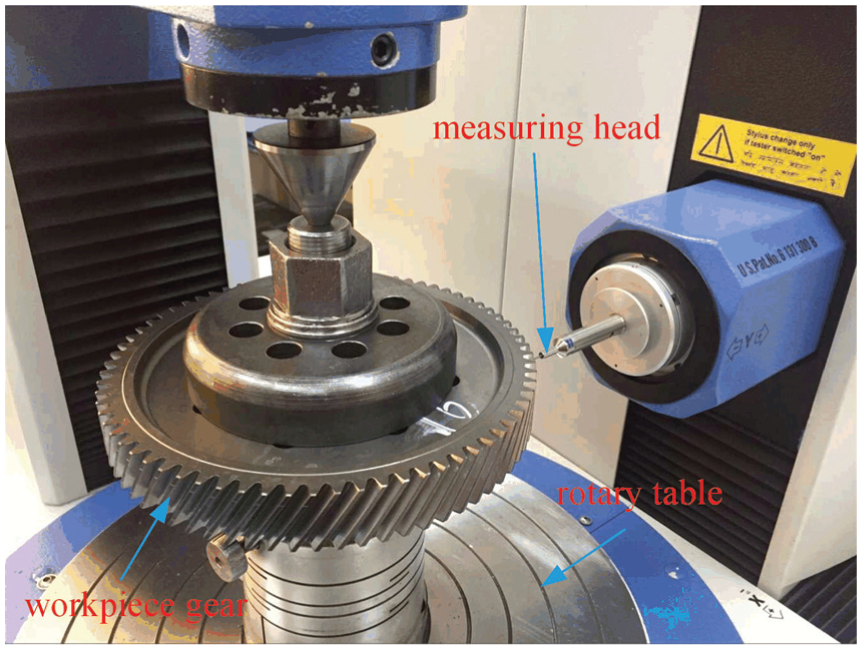
Gear measuring center Klingelnberg-P40.
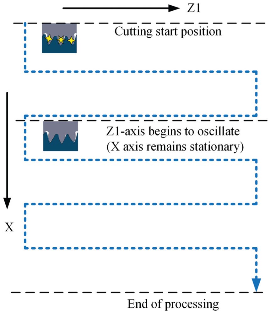
Incremental infeed of honing process.
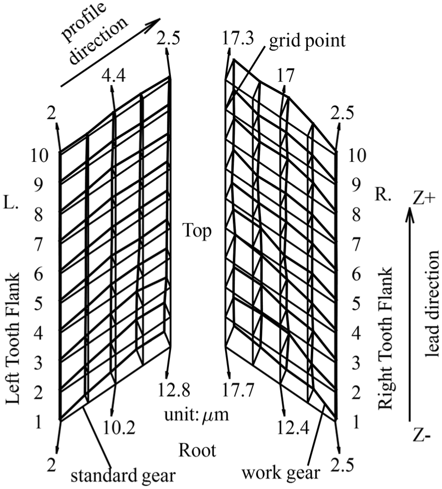
Measurement result of tooth surface contour error.
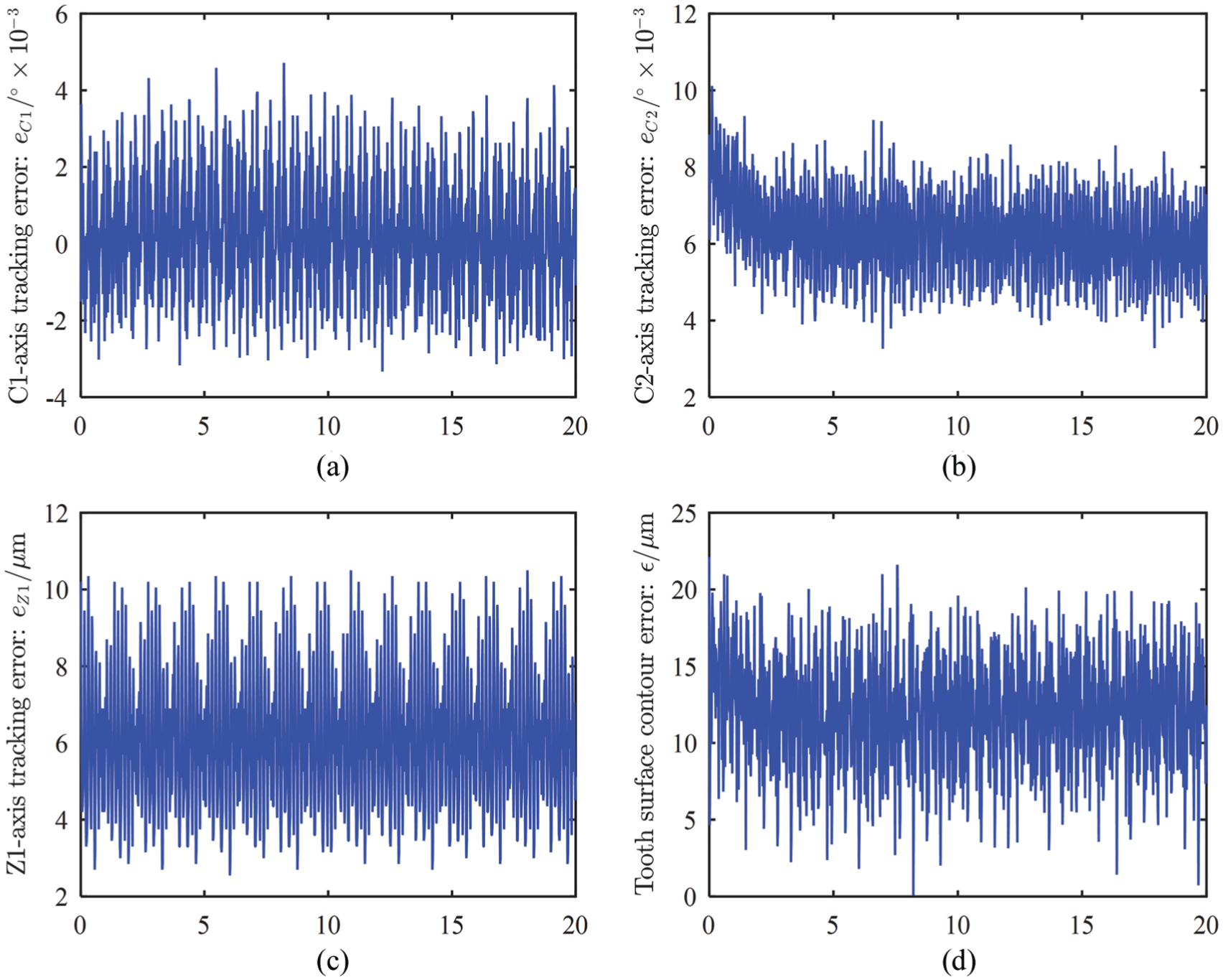
Tracking error and estimated tooth surface contour error during machining: (a) gear measuring width (mm), (b) gear measuring width (mm), (c) gear measuring width (mm) and (d) gear measuring width (mm).
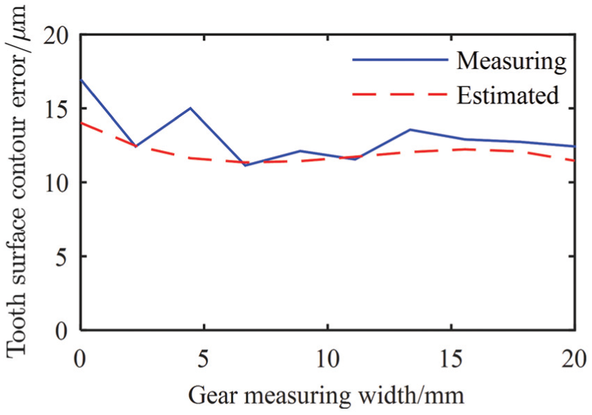
Comparison of measurement results and estimation results of tooth surface contour error.
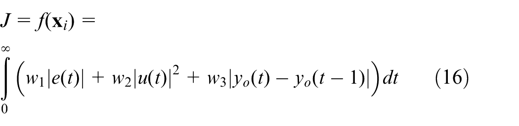
Simulation and discussion of AECCC
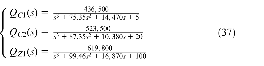
In order to demonstrate the effectiveness of the proposed control method, this article establishes a kinematics model to compare the control performance of the system in the case of non-ECCC, ECCC and AECCC. The transfer function of each axis is shown in equation (37) and the PID parameters are listed in Table 2. The constant speed signal is adopted as the input for each axis of the simulation control system, with a sampling period of 0.001 s. External disturbance and model uncertainty are introduced into the system at 0.5 and 1.0 s, respectively. The parameters of the workpiece gear and honing wheel used in the simulation are also listed in Table 1
PID parameters for the ECCC.
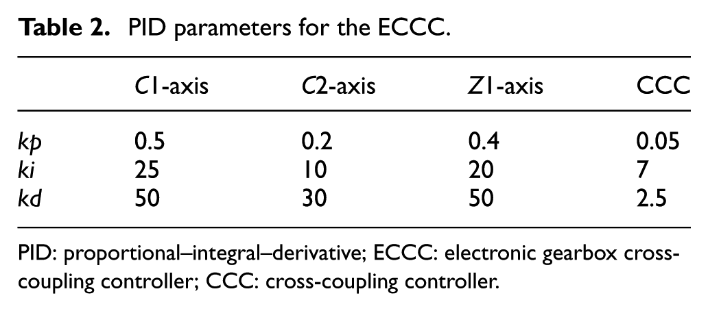
PID: proportional–integral–derivative; ECCC: electronic gearbox cross-coupling controller; CCC: cross-coupling controller.
The tracking error and the tooth surface contour error of the EGB control system are shown in Figure 18, from which it can be seen that each control strategy reduces the error in different degrees. The error criteria of control performance are shown in Table 3, where AIAE indicates the average integral of absolute error, and RMS indicates the root mean square of error. The unit of each criterion is “μm.” Comparing the control performance of ECCC with that of non-ECCC, the tracking errors of C1-axis, C2-axis and Z1-axis are reduced by 39.5%, 37.4% and 35.4%, respectively, and tooth surface contour errors are reduced by 28.1%. The reason why the ECCC controller can achieve better contour control performance is that it takes into account the multi-axis coupling and decoupling problems, while the non-ECCC only considers uniaxial compensation. However, the ECCC control method only compensates for tracking errors and tooth surface contour errors, resulting in failure to achieve the desired control accuracy, especially in the presence of external disturbances and model uncertainty. Compared with the non-ECCC control method, AECCC remarkably improves the control accuracy, with decreases of 60.8%, 59.9%, 49.7% and 65.6%, and basically satisfied the expected effect. Obviously, AECCC improves the control performance of EGB better than ECCC, while ECCC also reduces tracking error and contour error to a certain extent, compared to non-ECCC.
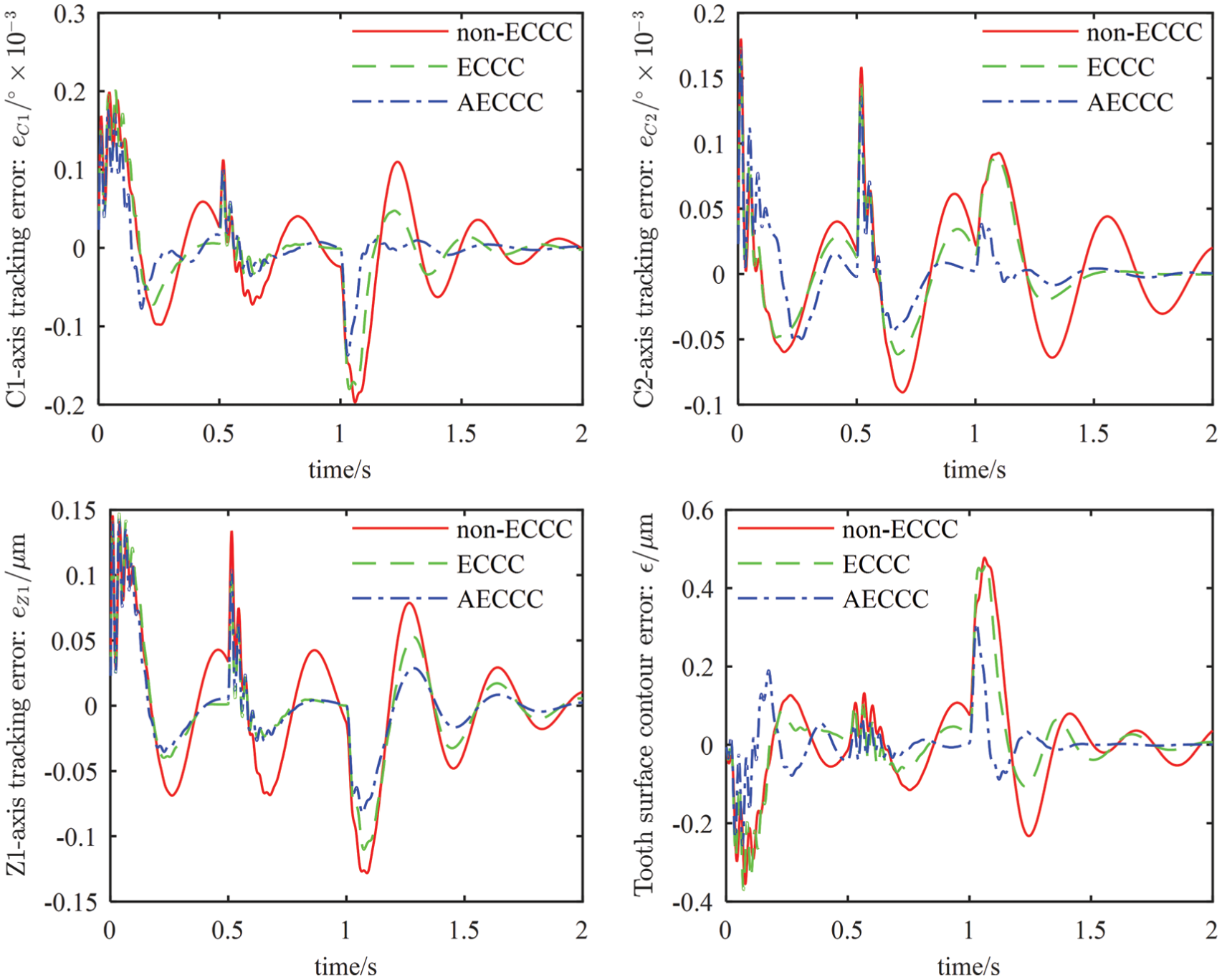
Comparison of simulated tracking errors and tooth surface contour error for different control schemes of EGB.
Comparison of AIAE and RMS values of tracking error and tooth surface contour error.
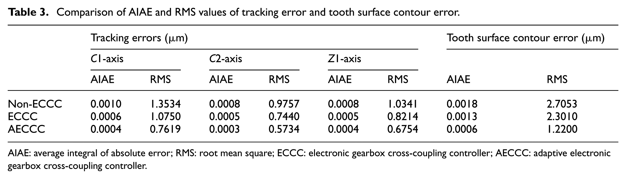
AIAE: average integral of absolute error; RMS: root mean square; ECCC: electronic gearbox cross-coupling controller; AECCC: adaptive electronic gearbox cross-coupling controller.
Experiment and discussion of AECCC
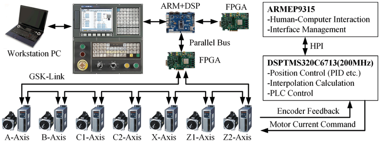
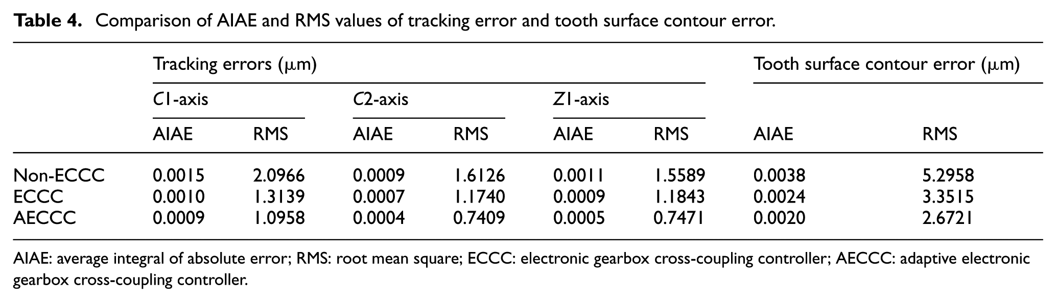
The effectiveness of the proposed EGB control method is verified by experiments on an extendible and modular CNC system developed independently (Figure 19), which consists of ARMEP9315 and DSPTMS320C6713. EGB control, interpolation calculation and programmable logic controller (PLC) control are implemented using C language in DSP. ARM completes human–computer interaction, interface management and other functions using C++ language. The DSP is connected to the servo drive and servo motor, equipped with 5000 r/min photoelectric rotary encoders to detect position and speed, using FPGA through the GSK-LINK bus. The parameters of workpiece gear and honing wheel used in experiment are shown in Table 4, the same as that in simulation. The tracking errors data in the last reciprocating oscillation period (shown in Figure 20) of each axis are collected to verify the effect of the proposed method.
Seven-axis internal gearing power honing machine used in experiments.
Comparison of AIAE and RMS values of tracking error and tooth surface contour error
AIAE: average integral of absolute error; RMS: root mean square; ECCC: electronic gearbox cross-coupling controller; AECCC: adaptive electronic gearbox cross-coupling controller.
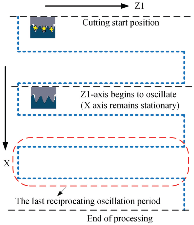
The honing feeding process adopted in the experiment.
The control performances of the three control strategies, non-ECCC, ECCC and AECCC, are compared in experiment, as illustrated in Figure 21. The values of AIAE and RMS of tracking errors and tooth surface contour errors are listed in Table 4, from which it can be seen that each control strategy reduces the errors in different degrees. For example, compared with the non-ECCC control strategy, the AIAE value of each axial tracking errors of the ECCC control is reduced by 33.1%, 21.9% and 24.6%, respectively. The AIAE value of tooth surface contour errors is reduced by 36.0%. The AIAE values of AECCC control errors were decreased by 43.2%, 51.1%, 52.1% and 47.8%.
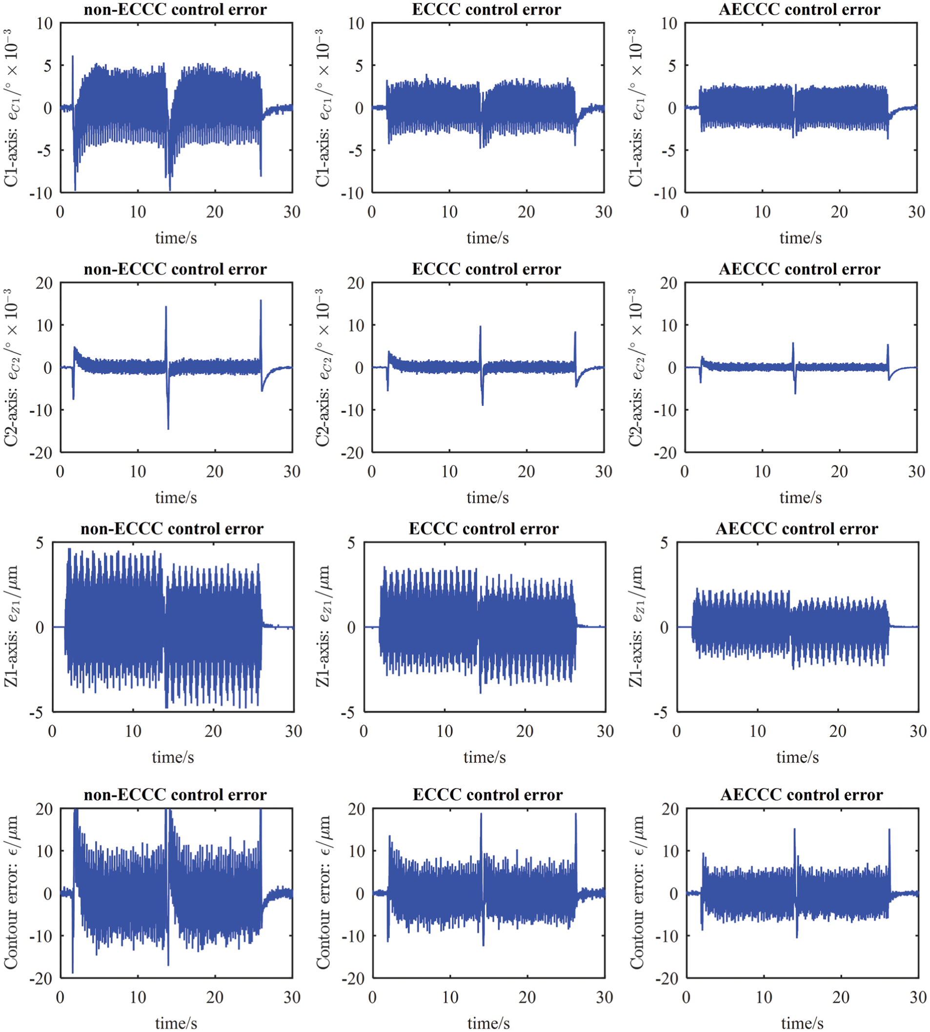
Experimental results of three control strategies for tracking error and tooth surface contour error.
Conclusion
In the process of gear machining, the tracking error of individual axis and the synchronous error of the EGB affect the machining accuracy of the gear to a great extent. In order to improve the precision of gear machining and reduce the influences of load fluctuation and model uncertainty on control performance, a general modeling method for tooth surface contour error and an AECCC architecture were proposed in this article. The modeling result shows that the tooth surface contour error is proportional to the tracking error of each axis, which provides the possibility for the implementation of the CCC. The ECCC and fuzzy PID controller whose universe of membership functions is optimized by PSO were seen as the central part of AECCC. Simulation and experiment results on internal gearing power honing machine Fässler HMX-400 have shown that the proposed modeling method can estimate tooth profile error very well. Compared with the non-ECCC and ECCC methods, AECCC can effectively improve the tracking precision and gear machining accuracy. Moreover, the proposed modeling and control compensation method can be used in other gear machine tools, such as gear milling, shaping, hobbing, scudding and grinding machine by changing the relationship of EGB.
Footnotes
Appendix 1
Declaration of conflicting interests
The author(s) declared no potential conflicts of interest with respect to the research, authorship and/or publication of this article.
Funding
The author(s) disclosed receipt of the following financial support for the research, authorship, and/or publication of this article: This work was supported by the National Natural Science Foundation of China under plan No. 51575154 and No. 51505118.