
Abstract
Performance, functionality, and cost determine the competitiveness of CNC systems. These factors often conflict with each other. Cloud computing provides an enabling technology to meet the multidimensional challenges, potentially leading to CNC systems with both better performance and functionality, and lower cost. This article presents the architecture of a cloud-computing-based CNC system. This system locates its frontend in a cloud virtual machine and provides the frontend as a service. The frontend in cloud, otherwise known as a cloud-enabled frontend, remotely displays the interactive interface at a client device. The application program for interaction on the client is lightweight compared with the traditional CNC human machine interface and can be easily integrated into mobile devices, such as laptops. The cloud-enabled frontend communicates with an NC device (also known as the backend) on the shop floor via the Internet or an intranet. Only real-time tasks run on the backend, while other tasks (semi-real-time or non-real-time) are executed on the cloud-enabled frontend. Thus, the computing ability and intelligence of CNC systems can be improved by a switch to the cloud architecture. In the proposed solution, users can also launch third-party software (e.g. CAD, CAM, and CAE) on the cloud-enabled frontend, making it more versatile due to a rich application environment.
Introduction
Intelligent manufacturing is a core technology of the new industrial revolution that includes the digitization, networking, and intelligentization of the manufacturing industry. 1 It has gained significant momentum in industry and academia in recent years. 2 The Industrial Internet in the United States, “Made in China 2025,” and “German Industry 4.0” all focus on intelligent manufacturing and a deeper integration of information and manufacturing technologies in order to advance the next industrial revolution.1,3 Because machine tools are the basic equipment in intelligent manufacturing, computerized numerical control (CNC) technology plays a crucial role in this process. At present, the major CNC systems (e.g. HNC8, FANUC, and SIEMENS) adopt the frontend and backend structure. 4 The frontend undertakes non-real-time or semi-real-time tasks, while the backend executes real-time numerical control (NC) machining. The two are located alongside a machine tool and interact with each other via communication bus (e.g. CAN, RS-485, or RS-232) or an intranet. To increase productivity and manufacturing performance, CNC systems have been further developed over the years to a point where they are quite powerful at present. However, the current CNC system architecture is not flexible enough to permit integration of intelligent applications into CNC systems, posing an obstacle to the development of intelligent manufacturing. That is, performance, functions, and cost conflict with each other in this model of CNC system architecture.
Virtualization technology offers a practical solution for resolving the above conflict. It is responsible for transforming heterogeneous manufacturing resources into isomorphic services while manufacturing resources are heterogeneous on storage format, description granularity, and management strategies. 5 Virtualization technology has been widely used in the field of computers, information security, and smart phones, while being seldom used in manufacturing industry.6,7 DMG MORI CELOS provides a CAD-CAM VIEW feature, allowing direct remote access to external CAD/CAM workstations by means of remote desktop virtualization. 8 Operating on the same principle, FANUC CNC systems can remotely use advanced applications (e.g. CAD, CAM, and NCGuide) running on PCs. 9 The above solutions provide CNC systems with better versatility and usability. However, they are still implemented using traditional frontend and backend model with no support for remote monitoring and control of NC machining. One purpose of this article is to present an improved architecture to address the mentioned deficiencies. The improved architecture can result in CNC systems having better performance, functionality, and flexibility due to the use of virtualization technology, easing the integration of any intelligent application (including remote monitoring and control) at a remote site.
In this article, the virtualization layer is based on cloud computing technology, which offers a scalable and flexible service over the Internet or an intranet.10–12 According to the definition of National Institute of Standards and Technology (NIST), cloud computing is a model for enabling ubiquitous, convenient, on-demand network access to a shared pool of configurable computing resources (e.g. networks, servers, storage, applications, and services) that can be rapidly provisioned and released with minimal management effort or service provider interaction.13,14 The key spirit of the cloud computing concept can be summarized as the ability to provide distributed, low-latency, on-demand, and quantifiable services. As a result, cloud computing creates new solutions and opportunities for modern enterprises, including the manufacturing industry. 15 It can improve the environment of product design, manufacturing process management, enterprise resource planning, and manufacturing resource management by providing a globally optimized solution. 14
Many studies, applying cloud computing in manufacturing, have been carried out. The key benefits of manufacturing as a result of cloud computing technology adoption are scalability to business size and needs, ubiquitous network access, and virtualization. 16 Y Shi 17 proposed a cloud CNC system, consisting of a cloud control node, a cloud measurement node, an adjustment drive unit, a real-time communication network, and access to the Internet. This system enabled cooperative manufacturing of multiple machine tools. The cloud control node and the cloud measurement node constitute a cloud layer, which in practice is merely a cluster of PCs connected through a real-time physical network. Hence, this CNC system retained the traditional frontend and backend model, suffering limitations in providing on-demand computing, storage, and network resources. Furthermore, it failed to lower manufacturing costs by any sizable margin. Li et al.18,19 proposed the concept of cloud manufacturing (CM), and researched the architecture, as well as the operation and application models of the CM system. However, the above models were not integrated into a CNC system. The CM system only provided services and applications outside the CNC system.
This article will introduce an architecture of a cloud-computing-based CNC system. This system moves the software modules from traditional physical frontend to the cloud, providing the frontend as a service (FAAS). The cloud layer provides virtualized resources (e.g. the virtual operating system, the virtual memory, and the virtual hard disk space) to support the improved frontend. There is a significant difference from how Y Shi described his cloud CNC system: the improved frontend in cloud (also referred to as a cloud-enabled frontend) is launched using the virtualization technology. The cloud-enabled frontend communicates with an NC device (also referred to as the backend) via the Internet or an intranet and displays its interactive interface at a remote client device (also referred to as the client). Furthermore, the backend undertakes only real-time tasks such as servo control, while the cloud-enabled frontend undertakes semi-real-time tasks (e.g. machining simulation) and non-real-time tasks (e.g. G-code editing). 20 Therefore, what this article proposes is a real cloud CNC system, presenting improvements in computation, interoperability, and on-demand provision of resources.
The FAAS approach shows four main advantages. First, it uses the cloud computing technology to provide on-demand resources or services for the backend and takes advantage of virtualization technology to improve availability of cloud resources. Second, it is possible to scale performance of a CNC system in response to a rise in demand. For example, resource allocations, such as that of virtual memory, can be varied dynamically. Third, the cloud provides a richer environment, supporting third-party software (e.g. CAD, CAM, and CAE) and user-defined applications. These applications are installed virtually on the cloud-enabled frontend. Then, users can access, via the Internet or an intranet, the cloud-enabled frontend and operate these applications to provide intelligent services for the backend. Finally, the cloud layer utilizes high-end servers as hardware carriers. They offer powerful computing resources, including CPUs and storage, to the cloud-enabled frontend.
Section “A cloud-computing-based CNC architecture” focuses on the overall system architecture of the cloud-computing-based CNC control approach. The working mechanism of the cloud-enabled frontend and the client is discussed. This section also considers how the FAAS approach becomes advantageous in computation, interoperability, and provision of on-demand resources. Section “The experiment” describes a machining experiment designed to confirm that the FAAS approach works in practice. The latency of this system is also analyzed. The article concludes with section “Conclusion and future work,” demonstrating the advantages of the proposed concept, as well as areas needing in need of improvements.
A cloud-computing-based CNC architecture
The FAAS approach separates the physical frontend from a CNC device and deploys the software modules in the cloud layer. The improved frontend is called the cloud-enabled frontend in this article. That is, this approach divides a proposed CNC system into the cloud-enabled frontend, the client, and the backend, as illustrated in Figure 1.
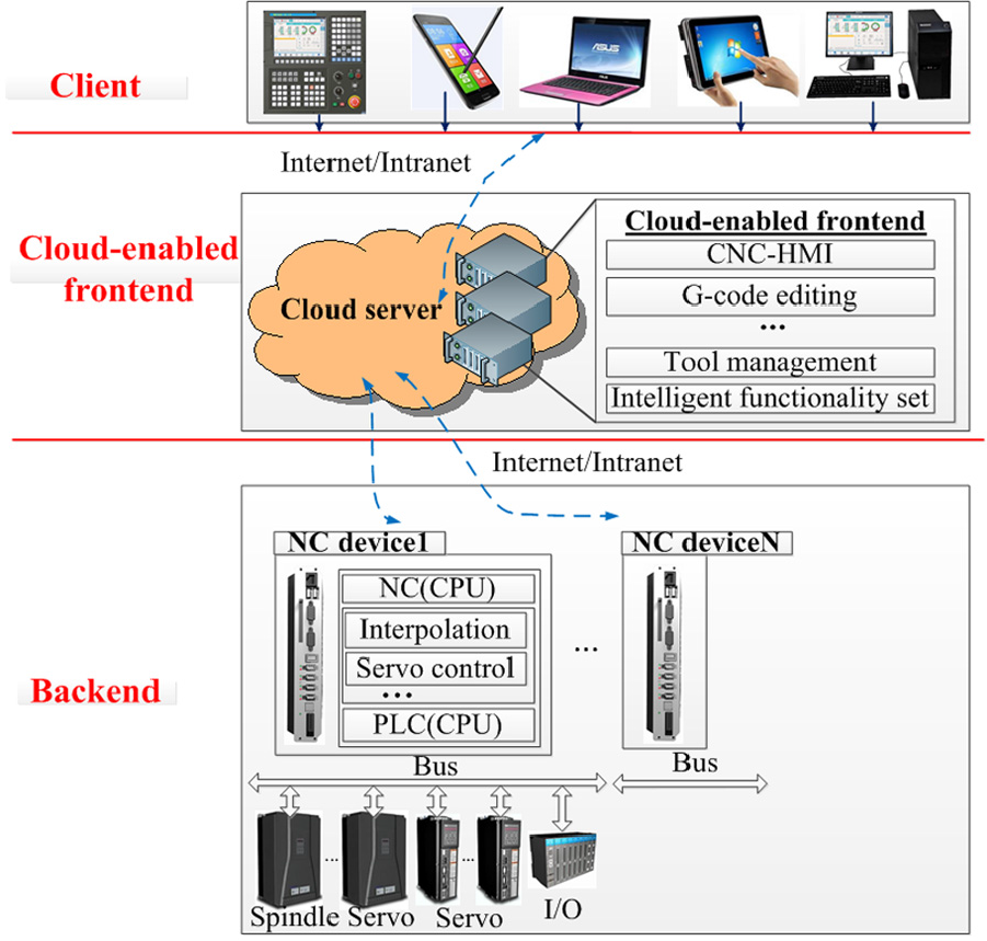
The cloud-computing-based CNC system architecture.
The backend, located in a workshop, mainly consists of a servo controller, programmable logic controller (PLC), an numerical control unit (NCU), and so on. It is responsible for real-time tasks covering position control, speed planning, interpolation arithmetic, and so on. 21 The operations of the machine-tool scram, pause, start-up, and shutdown are all done at the backend. The cloud-enabled frontend executes semi-real-time or non-real-time tasks. Online NC machining simulation is an example of a semi-real-time task, while non-real-time tasks include G-code editing, troubleshooting, tool management, NC parameter setting, commercial software (e.g. CAPP, MES, CAD, CAM, and CAE), and so on. The client provides operators with an interactive interface. It could be accessed on a PC, a laptop, or a smart phone.
A cloud-enabled frontend
A cloud-enabled frontend is a virtual machine (VM) located in the cloud layer. The cloud layer is built with high-performance servers. The cloud servers may be located in a workshop, a factory, or far away from the factory, because NC devices can interact with the cloud via the Internet or an intranet. In addition, the cloud-enabled frontend serves, via a network, its virtual desktop to thin client devices such as PCs, on which users can run a variety of intelligent applications. Such applications are displayed similarly to appstores (Figure 2). It is worth noting that there is a special application named CNC-human machine interface (HMI), corresponding to software functions and modules of a traditional frontend.
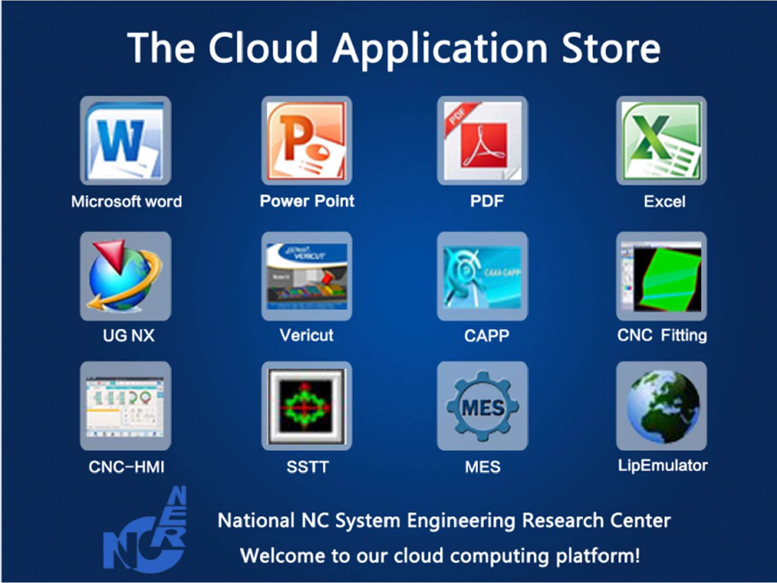
An interactive interface of the cloud-enabled frontend.
Using the just mentioned appstore, users can remove or modify existing applications or install new ones; however, such operations on CNC-HMI are not allowed. This is because CNC-HMI has to be closely coupled to the backend, while monitoring and control of NC machining, such as G-Code editing and the configuration of tool parameters, are performed remotely. Figures 3 and 4 show the two corresponding kinds of CNC-HMI interfaces.
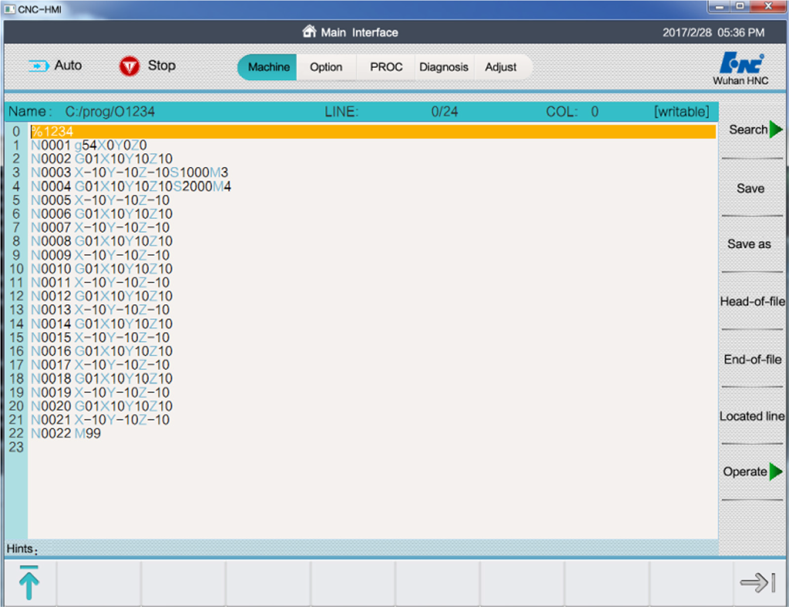
The interface used to edit the G-code.
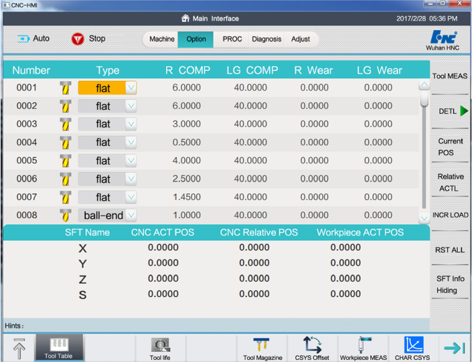
The interface used to set the tool parameters.
In the proposed solution, the portability of CNC-HMI influences the adaptability of the whole CNC system. CNC-HMI is programmed with Qt, a cross-platform application framework widely used to develop application software with a graphical user interface (GUI).22,23 Qt enables developers to target, with a single code base, various desktop, embedded and mobile operating systems, as well as multiple screens. 22 Therefore, Qt’s advantages such as the cross-platform support and being intuitive ensure that the CNC-HMI application is easily portable across platforms. Launched in a VM, the cloud-enabled frontend can run any operating system (e.g. Windows or Linux) from the corresponding system image to provide the required platform for CNC-HMI. The above strengths of CNC-HMI and the cloud-enabled frontend make the cloud-computing-based CNC system adaptable and flexible.
Along with software functions, the FAAS approach provides storage as a service. Storage resources are allocated at the cloud-enabled frontend as virtual hard drives (VHD), which can be resized to increase their capacity and partitioned. Machining data of NC devices are uploaded to these VHDs, with users being able to access the data from anywhere and at any time.
Separating machining data for a single backend is necessary in order to keep control and production safe. The FAAS approach achieves this goal by establishing a one-to-one relationship between the cloud-enabled frontend and the backend. Thus, the processing of a single machine tool is kept relatively isolated from that of others. Providers can optimize resource allocation at the cloud-enabled frontend to meet a specific processing demand.
The elasticity of cloud resources resolves the on-demand resource allocation and computational issues existing in traditional CNC systems. On one hand, the cloud servers’ powerful software and hardware configurations (including CPUs, RAM, hard disks, etc.) can be used to provide more capacity and computing power to CNC systems. On the other hand, the virtual resources of the cloud-enabled frontend can be expanded to meet the fluctuations in processing demands. Once no longer needed, these resources will be reallocated to other uses.
The proposed approach simplifies NC devices, resulting in lower costs for machine tool providers. NC devices do not need to perform complex computations, because semi-real-time and non-real-time tasks are executed in the cloud layer. As a result, they need less memory and hard disk capacity. The cost of hard disk drives (HDD) used in cloud servers is lower than the cost of solid state drives (SSD) of the same capacity used in a traditional frontend. It is possible that in the future, NC devices might not include display units, as the latter would be replaced by thin clients.
The client
The client communicates with the cloud layer using the Remote Frame Buffer (RFB) protocol, a simple protocol for remote access to GUIs.24,25 Because it works at the frame-buffer layer, it is applicable to all windowing systems and applications, including X11, Windows, and Macintosh. The RFB protocol can be used for communications between the client and the cloud-enabled frontend, regardless of the operating systems they run. The remote endpoint where the user (i.e. the display, the keyboard, and/or the pointing device) is located is called the RFB viewer. The endpoint where the changes to the frame-buffer originate (i.e. the windowing system and applications) is known as the RFB server. In the FAAS approach, the client includes an integrated RFB viewer, called the cloud-enabled remote desktop viewer (henceforth referred to as the C-RFB viewer), while the cloud layer has an RFB server called the cloud-enabled remote desktop server (henceforth referred to as the C-RFB server).
In what follows, this article will describe how the cloud-enabled frontend and the client communicate with each other. The client requests access to the required cloud-enabled frontend by providing the login credentials (the IP address and the port of the server, hosting the cloud-enabled frontend, and the password). Then, the cloud-enabled frontend provides its desktop’s pixel data to the client, where the remote virtual desktop (i.e. the virtual interactive interface) is shown to users. Although the desktop resolution of the cloud-enabled frontend is fixed at 1024 × 768, the virtual interactive interface displays its output at the appropriate scale, according to the client’s screen size. User operations are received by the virtual interactive interface, while their actual processing occurs in the cloud layer.
A typical control flow of the FAAS approach is described as follows (Figure 5):
A user inputs an instruction using an input device, such as a keyboard or a mouse.
The client forwards the instruction to the cloud-enabled frontend.
The cloud-enabled frontend produces the response to the above instruction and generates a control command (e.g. a servo control) for the backend.
Once the control command has been received, the backend makes the corresponding movements and sends its feedback to the cloud when necessary.
The cloud-enabled frontend provides the new desktop data to the client.
The client refreshes the screen seen to the user.
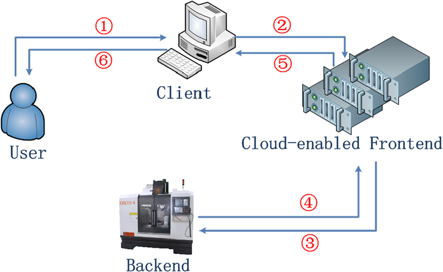
A typical control flow in FAAS approach.
Powered by the C-RFB server, a cloud-enabled frontend supports simultaneous access by multiple viewers, whose interactive interfaces are synchronized. Hence, there can be a one-to-many relationship between the cloud-enabled frontend (or backend) and the client. Developed in Qt, the C-RFB viewer is also cross-platform and runs on all operating systems. It can run on any display device, such as a PC or a laptop. As a result, remote monitoring and control of NC machining are made possible. Compared to using a traditional CNC display device, the operations are equivalent to those on a traditional CNC system.
Additional features of the cloud-computing-based CNC system
The cloud-computing-based CNC system also outperforms a traditional one in interoperability. It is capable of integrating third-party software (e.g. CAPP, CAD/CAM/CAE, PDM, PLM, and MES), as shown in Figure 6. In the cloud application store, such software can be installed or removed on demand. These programs can run well in the cloud and provide the corresponding services. User-defined programs such as a G-code simulator are also supported. This will reduce the developers’ learning curve and encourage them to concentrate on improving the performance of the CNC system instead of working on lower layers of the system.
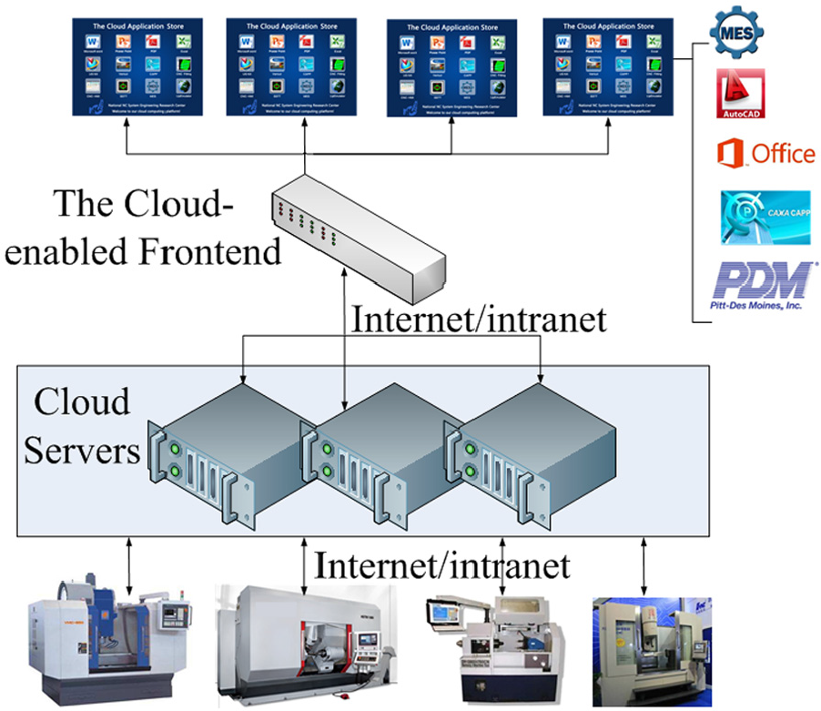
A general solution to obtaining cloud services for local NC devices.
Therefore, the cloud-enabled frontend is not intended merely for NC machining, but may also be used for other purposes, such as G-code auto-programming, CAD/CAM/CAE, and MES. This feature unifies the scattered manufacturing processes because all related actions can be performed at the client device, resulting in a more efficient preparation for processing.
The experiment
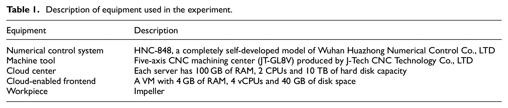
This section illustrates a workpiece being machined by the cloud-computing-based CNC system. The equipment and the numerical control system used in this experiment are described in Table 1.
Description of equipment used in the experiment.
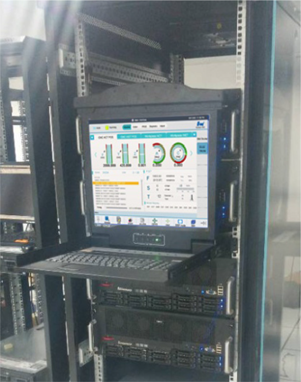
The experiment was conducted in the Mechanical Science and Engineering College of Huazhong University of Science and Technology. The machine tool was located in the ground-floor workshop, shown in Figure 7. The cloud center, shown in Figure 8, consisted of four Dell servers located on the fourth floor, 300 m (measured as a straight line distance) or so away from the machine tool. Such a cloud center, configured as described in Table 1, could serve at least 30 machine tools. The cloud-enabled frontend was a Windows 7 VM running on a single server. The client (a PC and an iPad shown in Figure 9) was located in another room on the same floor as the cloud center, approximately 100 m from the cloud center and approximately 400 m from the machine tool.
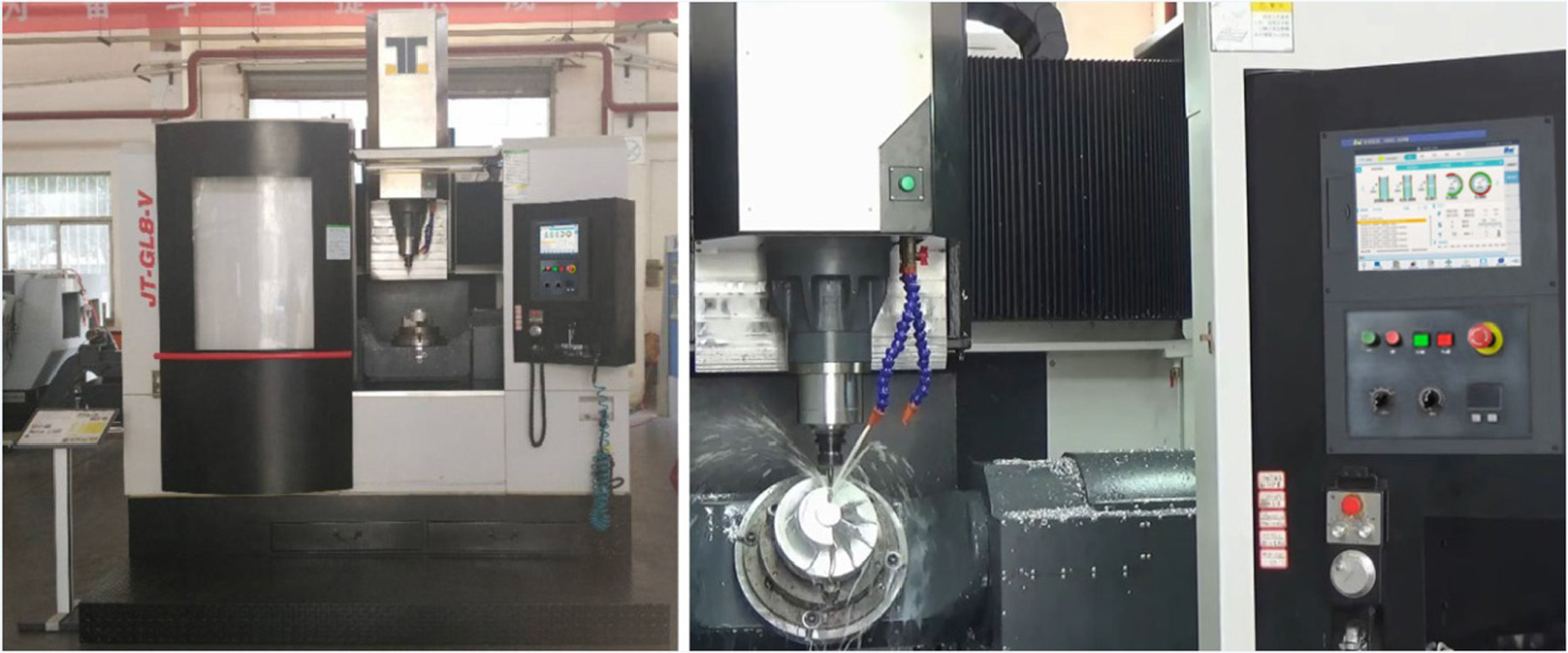
The workpiece machining process.
The cloud center.
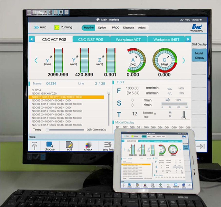
Interactive interfaces displayed on a computer and an iPAD.
In the workshop, experiment workers installed tools, fixtures, the roughcast, and so on. After accessing the cloud-enabled frontend from the client, the experiment workers completed the G-code automatic programming using Unigraphics NX (UG), the machining simulation using VERICUT, the G-code optimization by a user-defined optimization application, G-code editing with CNC-HMI and, finally, commenced CNC machining, as shown in Figure 7. Using an iPAD, the experiment workers were able to monitor or control the machining process over the network anytime and from anywhere. The CNC system produced a defect-free impeller without any warnings or error messages.
Due to communicating over the Internet or an intranet, command latency is a comparatively important factor affecting the system performance. Developers programmed a function in CNC-HMI to calculate the response time for user commands. The experiment workers typically require several kinds of data (including axis, register, channel, and tool data) from a PC. The results are shown in Table 2. For comparison, the experiment workers performed another impeller machining using a traditional CNC system with the same CNC-HMI settings, the G-code, and the machine tool. The results are also shown in Table 2.
The latency of CNC systems.
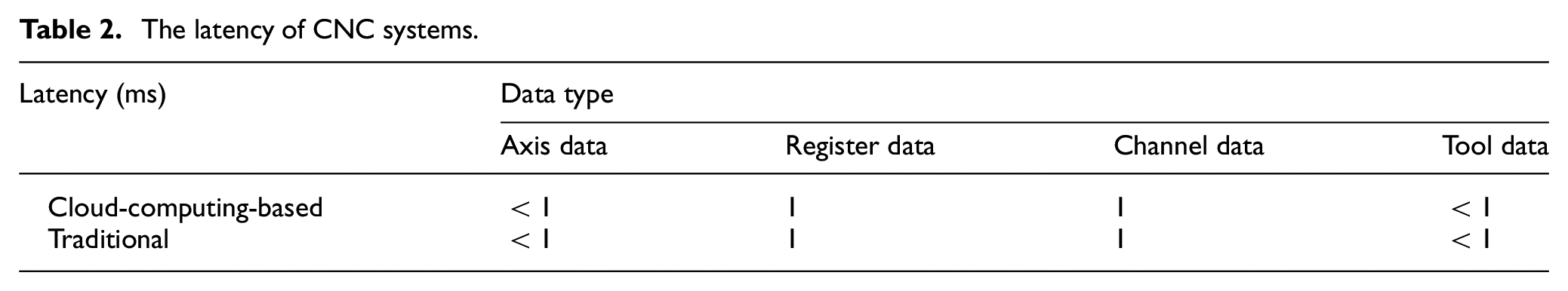
As seen in Table 2, there are no apparent differences in command latency between the cloud-computing-based CNC system and the traditional one under the network conditions that existed during the experiment.
In what follows, the reference bandwidth for the proposed CNC system will be computed. Between forwarding user commands from the client to the cloud-enabled frontend and transmitting NC machining data between the cloud layer and the backend, the largest share of bandwidth is used to forward the pixel data from the cloud-enabled frontend to the client. The largest amount of pixel data in a single transmission is 1024 × 768 bytes. Generally, the client would reload any changed regions, with the size of the pixel data being below 1024 × 768 bytes. Therefore, the present calculation only takes into account the maximum 1024 × 768 bytes of pixel data and takes the reload time of the entire virtual interactive interface to be the time needed for a single transmission. In the course of 10 tests on a PC, the values of 0.8, 1, 1.2, 0.8, 1.3, 1, 1.2, 0.7, 1, and 0.7 s have been obtained. Thus, the average single transmission time (or AVE-TT) is 0.88 s, according to the following equation (1)

The conversion between bit and byte is shown in equation (2)

Let us use NS to denote the network speed in bps (bits per second), and PD to denote the number of pixels in 1024 × 768 bytes of pixel data. Then, NS is calculated according to equation (3)

Substituting the respective values into equation (3), NS is found to be approximately 7.15 × 10⁶ bps.
Thus, cloud-computing-based CNC systems can work well over network links providing 7.15 × 10⁶ bps or higher bandwidth. However, this is not the minimum bandwidth requirement.
Conclusion and future work
A cloud-computing-based provision of a frontend for machine tools eliminates the disadvantages of current CNC systems in versatility, extensibility, and openness. Because a cloud server can provide services for more than one machine tool, the cloud platform can be centrally maintained and administered by qualified staff. Centralization would also considerably reduce the cost of commissioning, maintenance, and operation of machine tools. An amount of savings equal to that realized by moving the traditional physical frontend to the cloud could also be expected for CNC systems as a result of simplifying the hardware (e.g. reducing the amount of memory and the hard drive space, and removing the need for NC display devices) of current CNC devices. Furthermore, the cloud layer provides a richer environment for a variety of intelligent applications, as well as a powerful computing resource.
In conclusion, the FAAS approach yields a CNC system with a higher flexibility, greater versatility, and a higher computational power, yet a lower cost. In the future, we intend to focus our efforts on generalizing the proposed CNC system into the areas of education and industry. In addition, we plan to research the application of big data to raise the data-processing capacity of this system.
Footnotes
Acknowledgements
The authors acknowledge the help of Ping Wang and Jie Wang.
Declaration of conflicting interests
The author(s) declared no potential conflicts of interest with respect to the research, authorship, and/or publication of this article.
Funding
The author(s) disclosed receipt of the following financial support for the research, authorship, and/or publication of this article: The National Key Technology R&D Program of the Ministry of Science and Technology of China (2012BAF17G01) and the Development and Comprehensive Validation of an Open High-grade CNC system, Servo Units and Motor Products (2012ZX04001-012). The interconnection protocol standard and verification of CNC machine tools; The tool whole process life model based on cutting data (Grant/Award No. 51675204) and The analysis method of three-dimensional chromatogram for CNC real-time data (Grant/Award No. 51575210).