
Abstract
Three-dimensional model–based virtual assembly process planning plays an important role in assembly design of complex product and is typically time- and resource-intensive. There are limited effective solution frameworks for delivering the three-dimensional model–based assembly process information to assembly field in order to directly guide the assembly tasks on site. A cloud service architecture for mobile three-dimensional model is proposed to address these challenges. Under this cloud computing architecture, this article introduces a dynamic assembly simplification approach, which regards the virtual assembly process of complex product as an incremental growth process of dynamic assembly. During the growth process, the current-assembled-state assembly model is simplified with appearance preserved by detecting and removing its invisible features, and the to-be-assembled components are simplified with assembly features preserved using conjugated subgraphs matching method based on MapReduce. The proposed approach has been tested on several cases, and the results show its feasibility and superiority.
Keywords
Introduction
Three-dimensional (3D) model–based virtual assembly process planning is an important part of complex product design. It is of great significance for the rationality verification of complex product design, shortening the design cycle and reducing the cost. Meanwhile, the assembly tasks on assembly field are of high mobility. With the development of mobile computing and wireless network technologies, it seems that using mobile devices on assembly field to deliver, demonstrate and interact with 3D model–based assembly process information (i.e. 3D assembly order (3D AO)) of complex product is an irresistible trend.1,2 However, complex product usually has hundreds or even thousands of components; it is a challenge to demonstrate, interact with and deliver its 3D AO to the assembly field. One cannot just rely on hardware and computing resources improvement to cope with this issue,3,4 which could be addressed by an alternative approach named model simplification.
Computer-aided design (CAD) models are the primary carrier of the assembly process information contained in 3D AO. Besides, designing the assembly process based on CAD models and providing the assembly field with 3D AO are important parts of the implementation of model-based definition (MBD) technology in manufacturing industry. MBD technology aims to change the mode of product design and manufacturing by replacing the two-dimensional (2D) drawing with integrated 3D CAD model, which is the single source of product data and sole basis for the whole manufacturing process, including the assembling process. 5 Current 3D model simplification methods6–9 and lightweight 3D file formats—such as “JT,” put forward by Siemens AG, 10 and “XVL,” proposed by Lattice technology Inc. 11 —reduce the data volume of the boundary representation (B-Rep) CAD solid model by approximating the model with smooth rounded surfaces. For this reason, the simplified CAD model format has been changed to the one completely different from the original one, 12 that is, the engineering semantics information and features of the original CAD models have been lost during the simplification process. Therefore, these simplified CAD models are usually used to demonstrate the appearance of complex product other than being applied to several critical stages of virtual assembly process of complex product, such as collision detection, assembly path planning and 3D tolerance analysis, to name a few. Other B-Rep-oriented simplification methods simplify a CAD solid model either by recognizing and suppressing the blend features13–15 or by suppressing certain form features defined in the design history of the input model.16–20 However, all these works only simplify the single part but not the whole assembly model. Kanai et al., 12 Russ 21 and Koo and Lee 22 presented the model simplification methods which simplify an assembly by deleting the components entirely, and no operations of assembly features identification and preservation were performed, and it is impossible to support the demonstration of the progressive assembling process of complex product. In other words, they could only be applied to static assembly, the one that is at its final-completely-assembled state, but not suitable for dynamic assembly, which grows progressively from the initial state only containing the reference components to the final-completely-assembled state. Since the progressive assembling process is vital for the process engineers to design the 3D AO which will be delivered to the assembly field to provide assembly workers with intuitional guidance, more efforts are needed to investigate the B-Rep-oriented simplification method for dynamic assembly during the assembly process planning of complex product. As for the mobile 3D model technology, currently, it is mainly used in animation23,24 and construction site,2,25 but rarely in manufacturing engineering such as assembly field of complex product.
Xiao et al.26,27 presented CAD model simplification methods with assembly features preservation, which create prerequisites for delivering 3D AO to assembly field using mobile devices. Fast recognition of assembly features is the core algorithm. The problem of assembly features recognition has been translated into conjugated subgraphs matching. Based on the Ullmann algorithm 26 and the divide-and-conquer strategy, 27 assembly features can be recognized in real time when the scale of the corresponding graphs is not too large. As the scale of the conjugated subgraphs matching problem keeps increasing, the previous algorithms need to be improved to keep their efficiency. In the meantime, although the requirement for 3D AO on assembly field gets more and more imperative, it is costly and cumbersome for end users to install and maintain relevant software and operating system on mobile device for the demonstration and interaction of 3D AO. Therefore, a new problem-solving framework is needed for the large-scale dynamic assembly simplification and mobile 3D AO on assembly field.
In recent years, cloud computing has developed from concept speculation to successful application in various domains, including scientific computing,28,29 mobile communication, 30 product design and manufacturing 31 and military. 32 It shows that cloud computing has the advantages of solving large-scale problems efficiently and being suitable for operations on mobile devices. 33 Taking the massive social network graph query as an example, cloud computing has been adopted to solve this problem with an acceptable response time and lower computational cost. Different from a single super-large social network graph, the graphs this article deals with are categorized into two types: a large graph that keeps increasing and a set of relatively small graphs. And the application environment of the proposed approach in this article puts more emphasis on the efficiency of the graph algorithm. Although the cloud computing is suitable for handling massive graph, it is just a generic framework and still at its infancy; 34 how to perform the conjugated subgraphs matching in cloud computing environment and support 3D AO on assembly field needs more thorough research.
The rest of this article is organized as follows. Section “Cloud service architecture for mobile 3D model” presents the cloud service architecture for mobile 3D model and introduces the outline of the proposed approach. Section “Assembly model simplification with appearance preservation” describes a dynamic assembly simplification method with appearance preservation by detecting and removing the invisible features of current-assembled-state assembly model. Section “CAD model simplification with assembly features preservation” discusses dynamic assembly simplification method with assembly features preservation, and the focus is assembly features recognition based on conjugated subgraphs matching using MapReduce (MR). Section “Results and analysis” demonstrates the performance of the proposed approach and shows experimental comparison of this approach with the one presented in Xiao et al. 27 Conclusions are drawn in the final section.
Cloud service architecture for mobile 3D model
In large enterprises, because of business independence and system stability, usually, there is a proprietary information technology (IT) system for every important project. Consequently, it causes “chimney phenomenon,” that is, lots of independent IT systems whose computing and storage resources are idle for most of the time. Cloud computing is an ideal solution framework for the full utilization of the computing and storage resources in order to reduce costs. Due to safety concerns, manufacturing industry of complex products should employ the private cloud which can feasibly and effectively solve the problem of IT resource wasting, even though it is not as dazzling as public cloud. 35 In addition to cloud security, interoperability is another core issue to implement cloud computing effectively. As a general term, “interoperability” is a property referring to the ability of diverse systems and organizations to work together. This property has the concrete meaning of exchanging information and use of the information that has been exchanged between two or more systems or components. 36 Strictly speaking, interoperability is the capability to communicate, execute programs or transfer data among various functional units under specified conditions. 37 Usually, interoperability of infrastructure components is achieved by virtualization architectures, while data components interoperate via application components rather than directly in private cloud computing systems. This is especially applicable for the large enterprises to have complete control over their own data. A cloud service architecture is proposed for mobile 3D model based on private cloud. Figure 1 shows its logical layers and components.
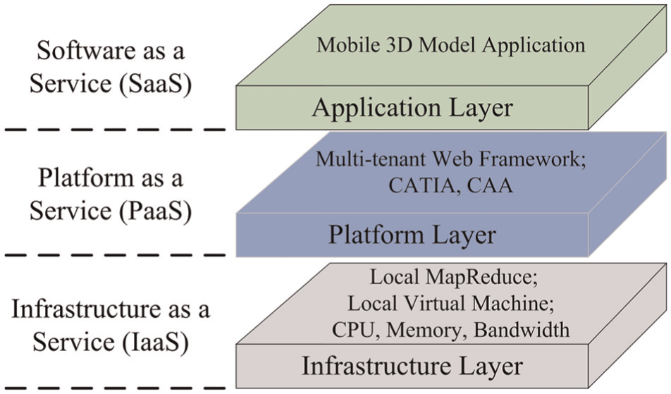
Logical layers and components of the cloud service architecture for mobile 3D model.
The proposed cloud service architecture consists of three layers: infrastructure layer, platform layer and application layer. The infrastructure layer creates a pool of computing and storage resources by virtualizing the physical resources. It also includes a parallel computing framework (i.e. MR). The platform layer builds on top of the infrastructure layer to lower the burden of deploying applications directly into virtual machine (VM) containers. 34 In this article, the widely used 3D design and assembly software Computer Aided Three-dimensional Interactive Application (CATIA) and its corresponding secondary development platform Component Application Architecture (CAA) are added to the platform layer. The application layer is the highest layer of this cloud service architecture, mainly including the mobile 3D model application. The cloud service architecture for mobile 3D model is demonstrated in Figure 2. It includes network, product data management (PDM) database and solver. In industry, some meaningful attempts based on mobile computing platforms have been made to provide a convenient means to access information on shop floor or construction site.38–40 Compared to these efforts, the major advantages of the proposed cloud service architecture over these systems include cost reduction, fast service provision and high service scalability promised by cloud computing. 33 Besides, the proposed cloud service architecture not only supports the end users on site to browse the desired information, like most of the existing mobile computing platforms do, but also offers the engineers with solution for the assembly process planning of complex product.
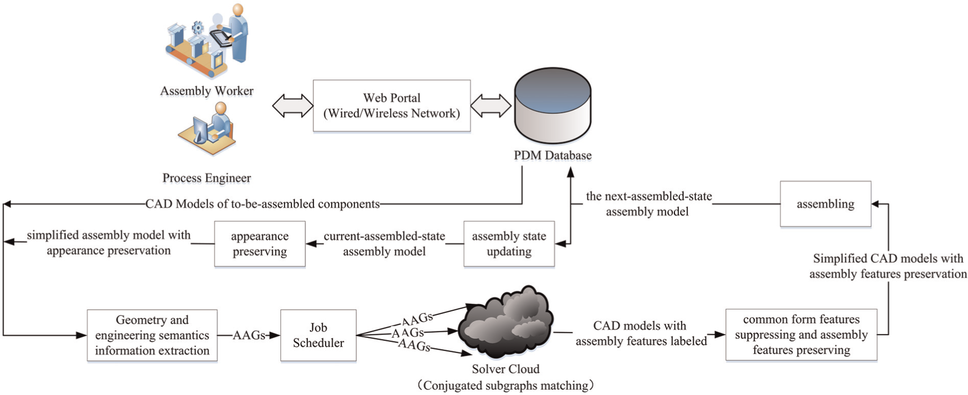
The cloud service architecture for mobile 3D model.
The outline of the proposed approach is described as follows. The invisible features of current-assembled-state assembly model
Assembly model simplification with appearance preservation
The invisible features of current-assembled-state assembly model
Kanai et al. 12 detected invisible features by pre-rendering the models from multiple view directions and reading the rendered results from the frame buffer. Despite the method is simple and effective, pre-processing is required, that is, it needs to generate mesh models per component of the assembly by tessellating surfaces of the CAD models and pre-render the mesh models based on OpenGL. However, as mentioned above, the triangular meshing of original CAD model is time-consuming and will change its format and cause data loss. Therefore, improvements on the invisible features detection method have been made so that it can be applied to the B-Rep CAD models directly. (Kanai et al. 12 could not directly access the frame buffer of a CAD system so that format conversion of CAD model is required, while the authors can access the frame buffer of the current mainstream CAD systems (e.g. CATIA, UG, Pro-E) since they have accumulated rich experience in the secondary development of these CAD systems.) The procedure to determine the visibility of the features in an assembly consists of the following three steps, which are viewpoints setting, information extraction of rendering results and visibility determination.
Step 1. Initialize the positions and directions of a set of viewpoints (see Figure 3) and assign an ID and color to each feature (recognized by form feature recognition method
41
) of
Step 2. Render each feature and
Step 3. According to the rendering results of every viewpoint, the maximum exposure rate of αth form feature among all view is calculated by
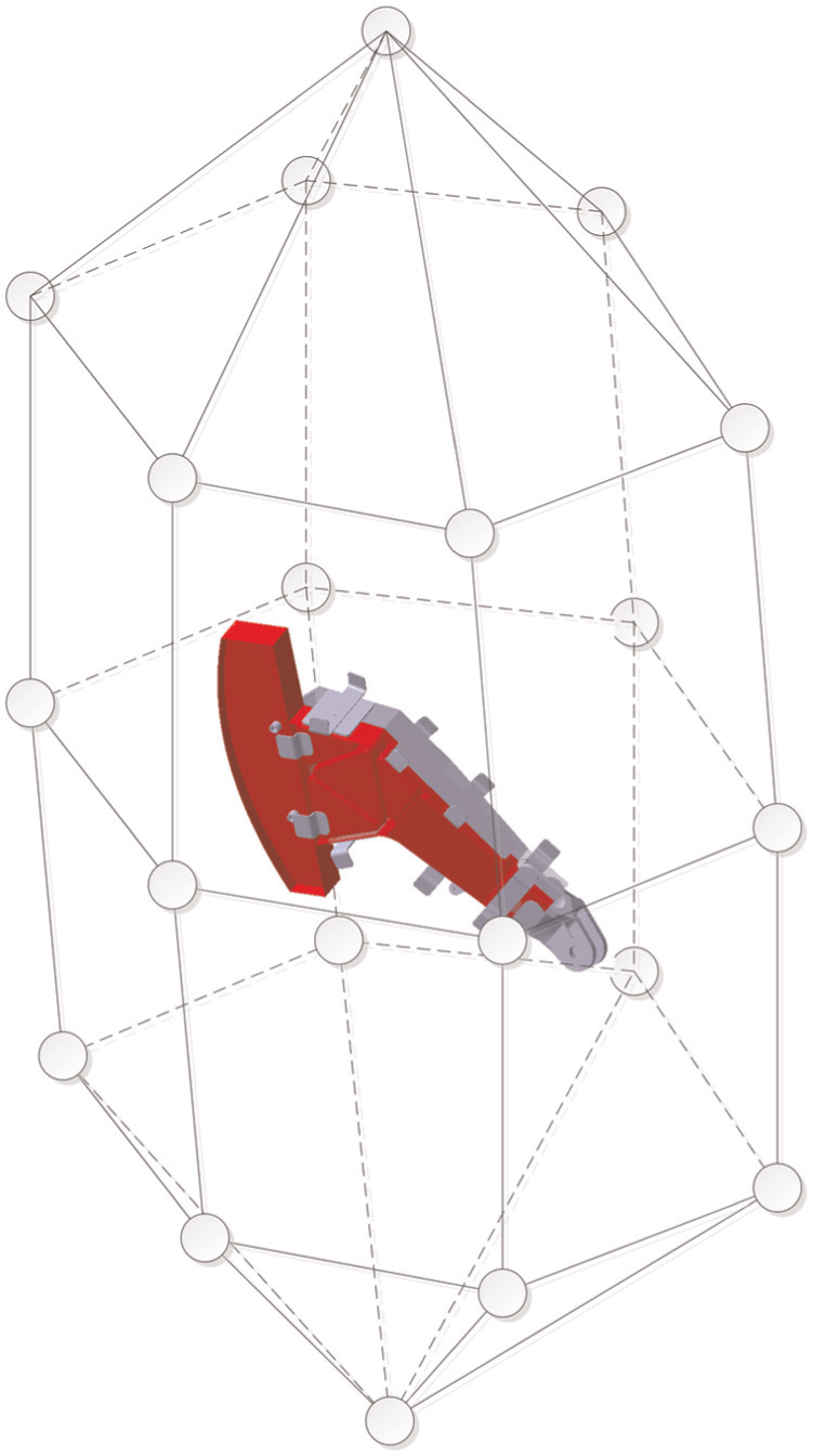
Viewpoints setting.
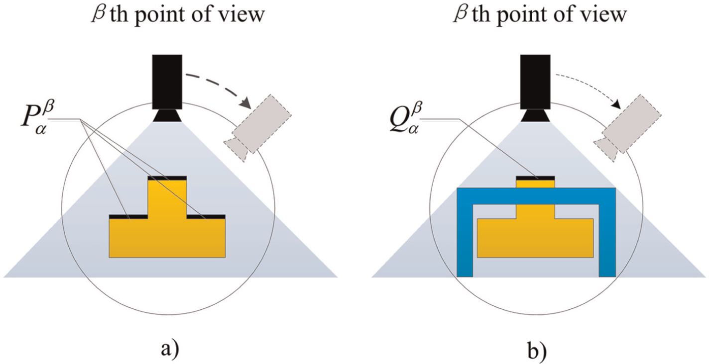
Information extraction of rendering results: (a)
If a feature is determined as invisible, it means that this feature has been occluded by other components or features, and there will be no barrier-free path for a to-be-assembled component to access the feature to complete the assembly process with it. In other words, an invisible feature either has completed the assembly process with some component or it will not form assembly features with any other form features.
However, it should be pointed out that the invisible features which are the reference features to other visible features need to be preserved, that is, an invisible feature can only be suppressed in condition that it will not cause geometric invalidation to other visible features after removing the invisible feature. An invisible feature is determined if it is suppressible based on its dependency chain, which is an array storing the features depending on this invisible feature.
A dependency matrix of adjacent features for every component is first established by extracting the geometry information of corresponding CAD model, denoted as
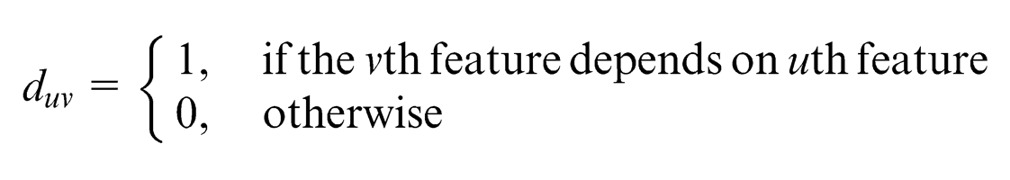
Since a feature usually has dependency relationship with only a few adjacent features, the dependency matrix
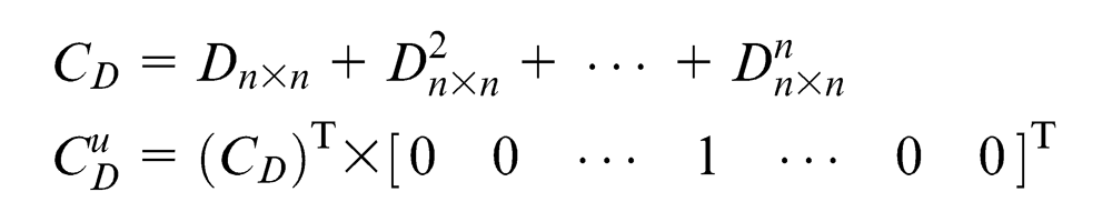
If the uth feature of a component is invisible, and there is no visible features in its dependency chain

And the dependency chain of all the features is
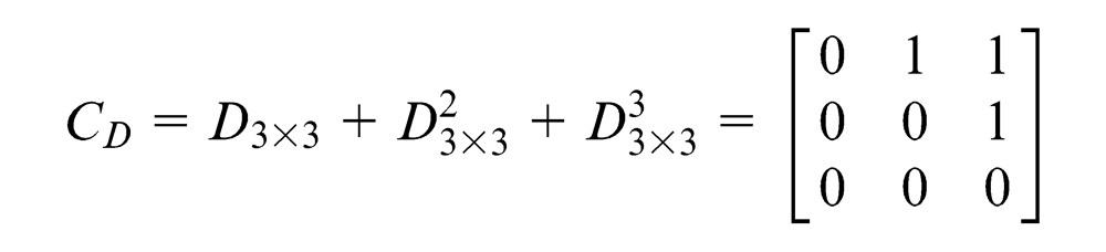
So, the dependency chain of feature f1 can be obtained by
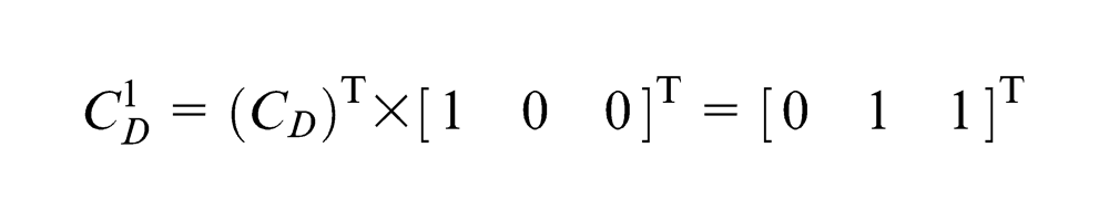
It shows that the invisible feature f2 and visible feature f3 are in the dependency chain of feature f1; therefore, the invisible feature f1 cannot be suppressed.
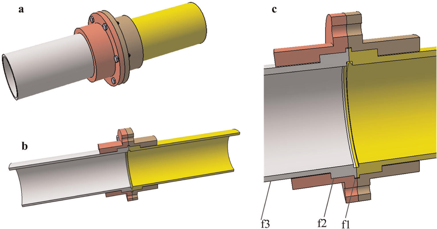
(a) Assembly model, (b) the cross-sectional view of the assembly model and (c) dependency relationship among the features.
Repeat the above operation until all the suppressible invisible features of
CAD model simplification with assembly features preservation
This section focuses on the simplification of currently selected to-be-assembled component
Assembly features definition and representation
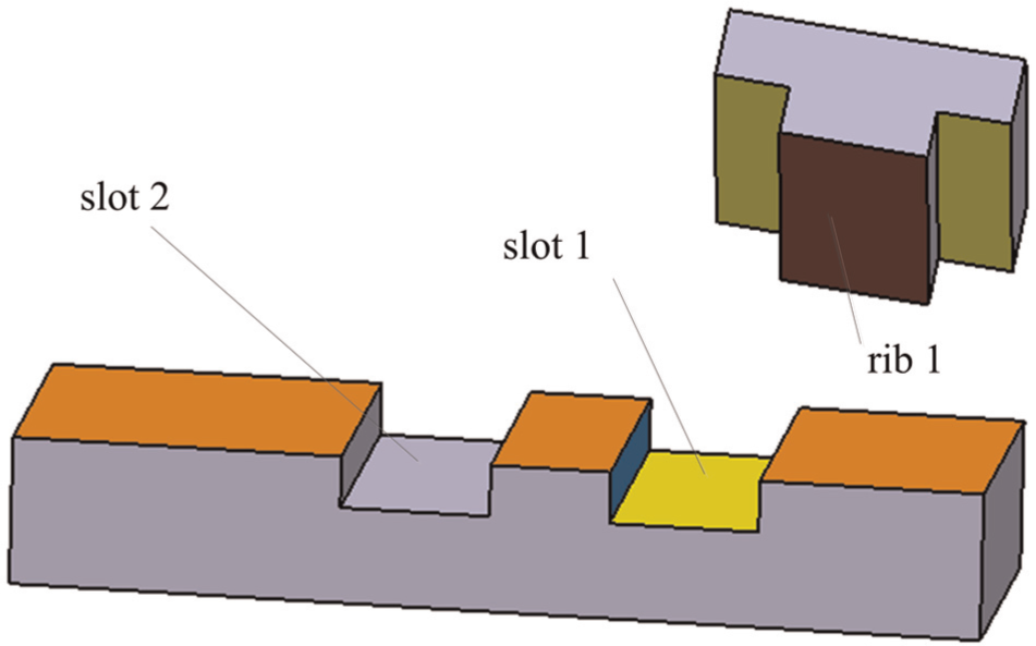
Features are generic shapes useful in some computer-aided applications, 42 and assembly features are essentially the connections between form features. So, discarding all the additional constraints, the core of assembly features is mating relation of two form features on different components of an assembly. There are more than 20 kinds of mating relations. But for the sake of stability and economy, mating relations can be roughly divided into “Against” (see Figure 6(a) and (d)) and “Fit” (see Figure 6(b), (c), (e) and (f)).43,44 In general, a class of mating relations usually has several subclasses. For instance, rib-slot in Figure 6(b) and pin-hole in Figure 6(c) are the subclasses of “Fit.” Meanwhile, every subclass of mating relations can derive many subinstances from its own basic instance. For example, the plane–plane type of “Against” mating relation in Figure 6(a) can derive surface–surface type in Figure 6(d), dovetail rib-slot in Figure 6(e) is derived from square rib-slot in Figure 6(b) and round pin-hole in Figure 6(c) can derive rectangular pin-hole in Figure 6(f). By analyzing these instances of mating relations, it shows that the mating areas of the components are similar in topology but have contrary concave–convex property. Based on this observation, the notion of “conjugation” is incorporated into the definition of assembly features. Conjugation, whose original meaning is the “yoke” upon two bulls in order to keep their footsteps consistent, 45 is the mating pair according to certain pattern, or, in other words, is coupled. So, assembly features are defined as “the conjugated mating relation between two form features on different components of an assembly.”
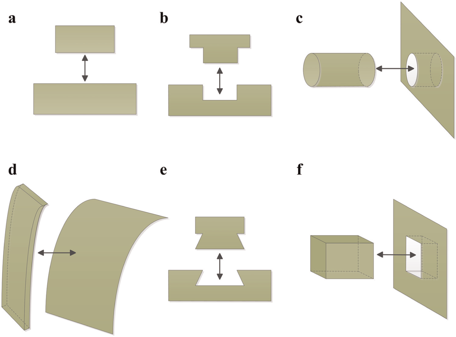
Assembly mating relations: (a) plane-plane, (b) square rib-slot, (c) round pin-hole, (d) surface-surface, (e) dovetail rib-slot, and (f) rectangular pin-hole.
AAG can effectively express B-Rep CAD model, and conjugated subgraphs between two AAGs represent the assembly features. Converting the CAD models into AAGs is the precondition for assembly features recognition using graph-based methods. In order to represent component
For every component of an assembly, search every face and create a node correspondingly; extract the geometric and engineering semantics information of each face, such as surface type (plane or curve surface), normal vector, region area (or radius of curvature for curve surface), surface roughness and so on, and associate them to the corresponding node. For every two faces, acquire their relationship (i.e. concavity) and set it as the edge attribute.
Conjugated subgraphs have the following characteristics (Figure 7). (1) Conjugated subgraphs are isomorphic with each other. (2) The attributes of corresponding nodes are mostly identical except the normal vector, that is, the surface types are identical, the directions of normal vectors are opposite, region areas are the same (not mandatory) or the radii of curvature for curve surfaces are equal, the corresponding surface roughness of mating surfaces should meet the dimensioning and tolerancing standard 47 and so on. (3) The concavity of corresponding edges is contrary.
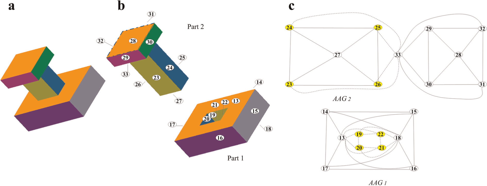
The conjugated subgraphs of round pin-hole: (a) an assembly of round pin-hole type, (b) the region-level representation of the assembly, and (c) the corresponding AAGs.
Assembly features recognition based on MR
As stated in section “Introduction,” the problem of assembly features recognition is translated into the problem of conjugated subgraphs matching. Specifically, given the currently selected to-be-assembled component
In graph theory, walk, tree and subgraph are usually used to represent the intrinsic characteristics of a graph. Walk is a simple and effective representation for the graphs which are simple in topology. The assembly features are usually simple in shape in consideration of stability and economy. Therefore, walk is suitable to represent the graphs of assembly features. Define
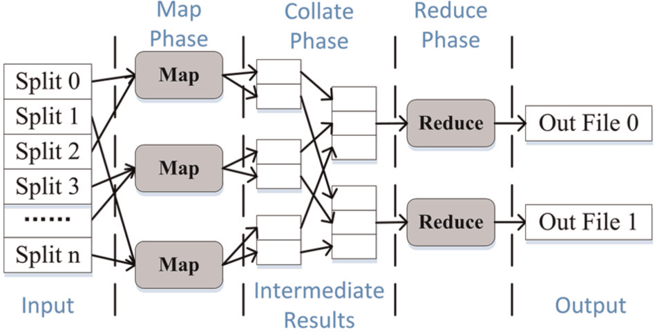
MR is a parallel programming paradigm and software framework for cloud computing. Computation in MR is divided into two major phases called map and reduce, separated by an internal grouping of the intermediate results.
48
This two-phase computation was developed after recognizing that many different computations could be solved by first computing a partial result (map phase) and then combining those partial results into the final result (reduce phase).
49
This framework automatically provides common services for parallel computing, such as the partitioning of the input data, scheduling, monitoring and intermachine communication necessary for remote execution. Users only need to design the serial map and reduce functions for specific applications,49,50 while the data parallel processing can be handled using the functions encapsulated in a library (e.g. Message Passing Interface (MPI) or Hadoop library) since the data processing is independent of specific applications. Figure 8 demonstrates the execution process of MR. According to the number of the worker machines, the input data are divided into pieces and represented in the format of
The execution process of MapReduce.
MR-based graph algorithms are mainly used to analyze large-scale graphs, which are categorized into two types, that is, a single large graph and a large set of small graphs. Current MR-based graph algorithms are either designed for a single large graph50,51 or large set of small graphs.
52
This article needs to discuss the graph algorithm both for a single large graph
The filter algorithm for reducing the search space of
Constraint satisfaction problem (CSP) is expressed as
The concept of CSP is adopted to the filter algorithm. Define labeling
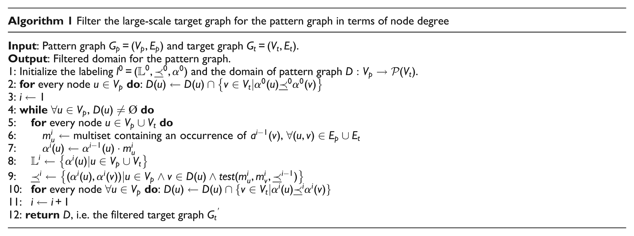
First, calculate the node degree of every node of
Conjugated subgraphs matching based on MR
The MR-based assembly features recognition algorithm is shown in Algorithm 2. This algorithm needs to deal with two kinds of objects: the walks through the target graphs and the steps forming walks. Walks and steps are all represented with
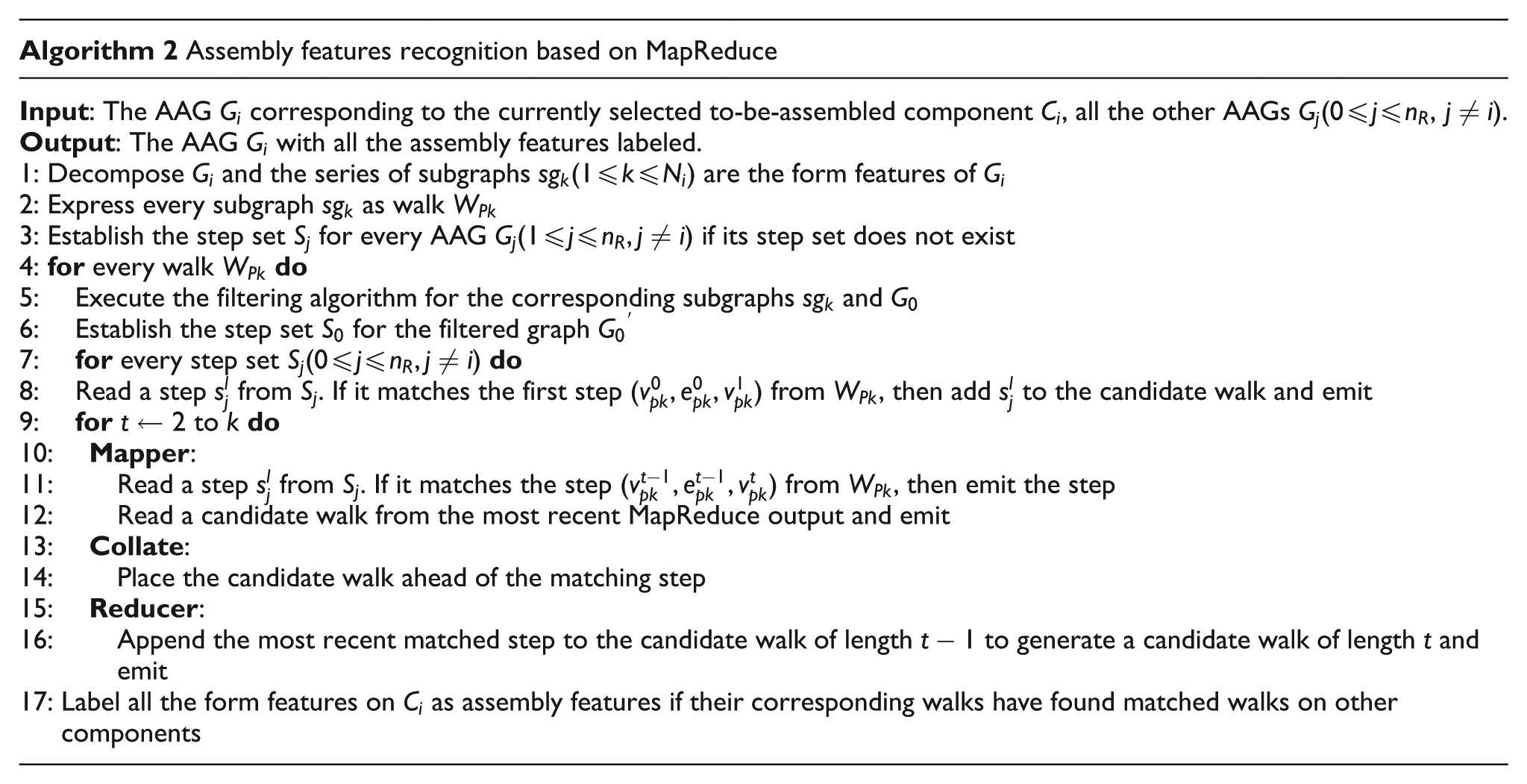
First, decompose
The implementation of assembly features recognition and preservation
This section details the procedure of assembly features recognition and preservation using conjugated subgraphs matching method described in section “Assembly features recognition based on MR” as follows:
Step 1. As stated in section “Introduction,” construct the AAGs of simplified current-assembled-state assembly model
Step 2. Apply Algorithm 2 in section “Conjugated subgraphs matching based on MR” to recognize the assembly features on the currently selected to-be-assembled component
Step 3. Suppress the features in set
Step 4. Update
The uniqueness of the assembly mating relation.
Results and analysis
Experimental setup
The experiments were performed on a three-node cluster. Each node is a HP Z820 station equipped with two 2.0 GHz Intel Xeon Hexa-core E5-2620 processors, 16 GB memory and 1 TB disk, running on 64-bit Windows 7. All these nodes are connected via a Gigabit switching hub. And CATIA is installed on one of the three stations to intuitively demonstrate the virtual assembly process using the proposed dynamic assembly simplification approach.
Based on CAA, which can integrate an algorithm or solution into CATIA system seamlessly, the proposed approach has been implemented as a C++ program using the MR-MPI library, 57 and a module has also been developed to test it on several CAD assembly models.
Assembly model simplification with appearance preservation
In Figure 10, the proposed assembly model simplification method with appearance preservation has been tested on a CAD assembly model of HP engine. First, the number of viewpoints
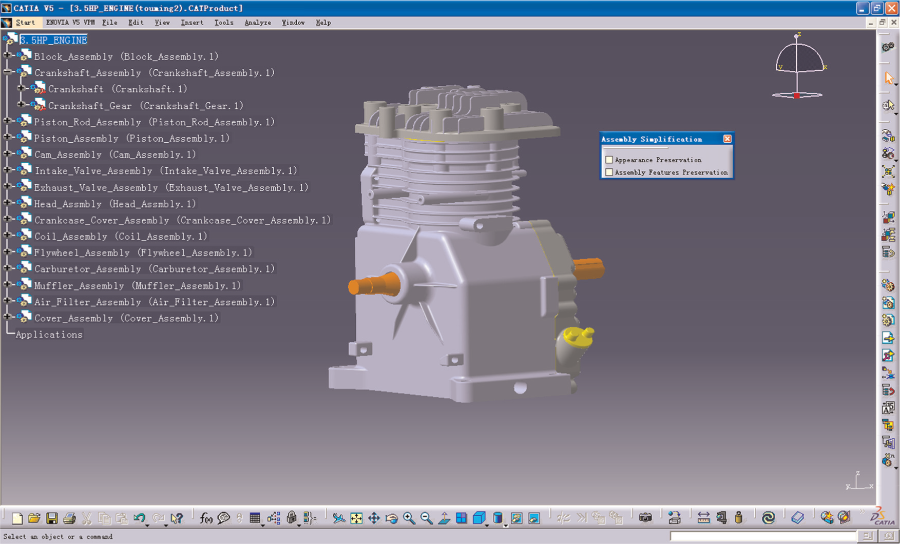
CAD assembly model of HP engine.
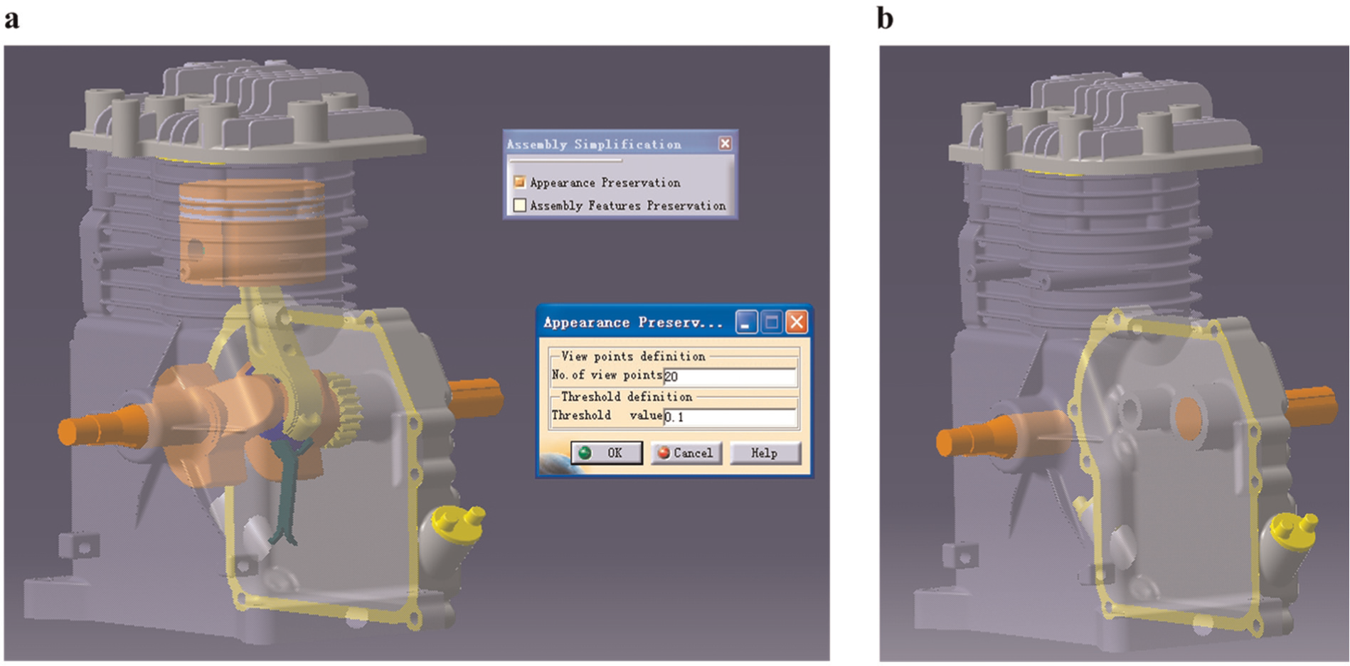
CAD model simplification with appearance preservation: (a) parameters setting and (b) the simplification result.
CAD model simplification with assembly features preservation
Given an assembly model (see Figure 12(a)), in order to demonstrate the mating relations of the components clearly, the simplification with assembly features preservation is carried out under exploded view (see Figure 12(b)). First, the geometric and engineering semantics information of the CAD models is extracted to construct the corresponding AAGs, and every face of the models is marked as shown in Figure 12(b). For the sake of efficiency, the blending features and other detail features (the deep pink features in Figure 12(b)) are pre-suppressed. The intermediate state of final simplification is shown in Figure 12(c). The proposed assembly features recognition method is applied to the models in Figure 12(c), and the assembly features are located and marked as yellow. Figure 12(d) shows the final simplification result with assembly features preservation after suppressing the common form features.
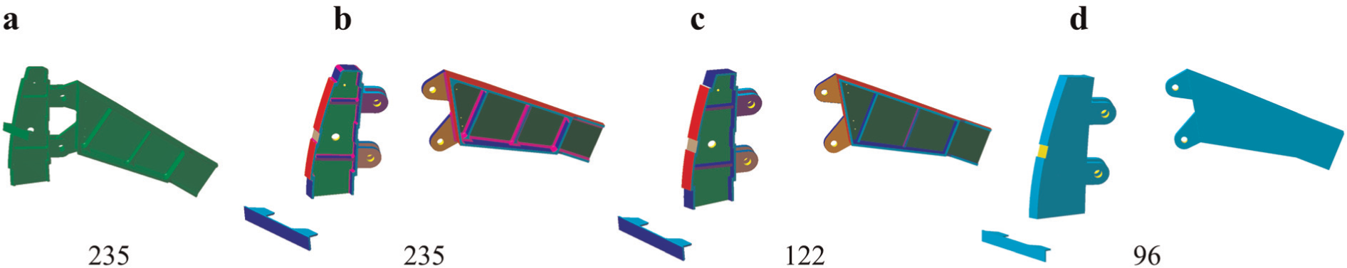
The simplification result: (a) the original CAD models of an assembly in its mating view, (b) the exploded view of the assembly, (c) simplification results after suppressing the blending features and other detail features, and (d) the models are simplified using the proposed simplification method with assembly features preservation.
The simplification degree of the CAD models is an important criterion by which to judge the effectiveness of the simplification method. In Figure 12(a), the original CAD models have 235 faces. After deleting the blending features and other detail features, the number of faces is reduced by 48.1%, and that is 122 faces, as shown in Figure 12(c). The number of faces drops to 96 after further suppressing the common form features (see Figure 12(d)). It confirms that the blending features dramatically increase the data volume of CAD models. 15 On the contrary, the assembly features are usually simple in shape in consideration of stability and economy. So, it will not increase the complexity of the CAD models too much if the assembly features are preserved. More examples are demonstrated in Figure 13.
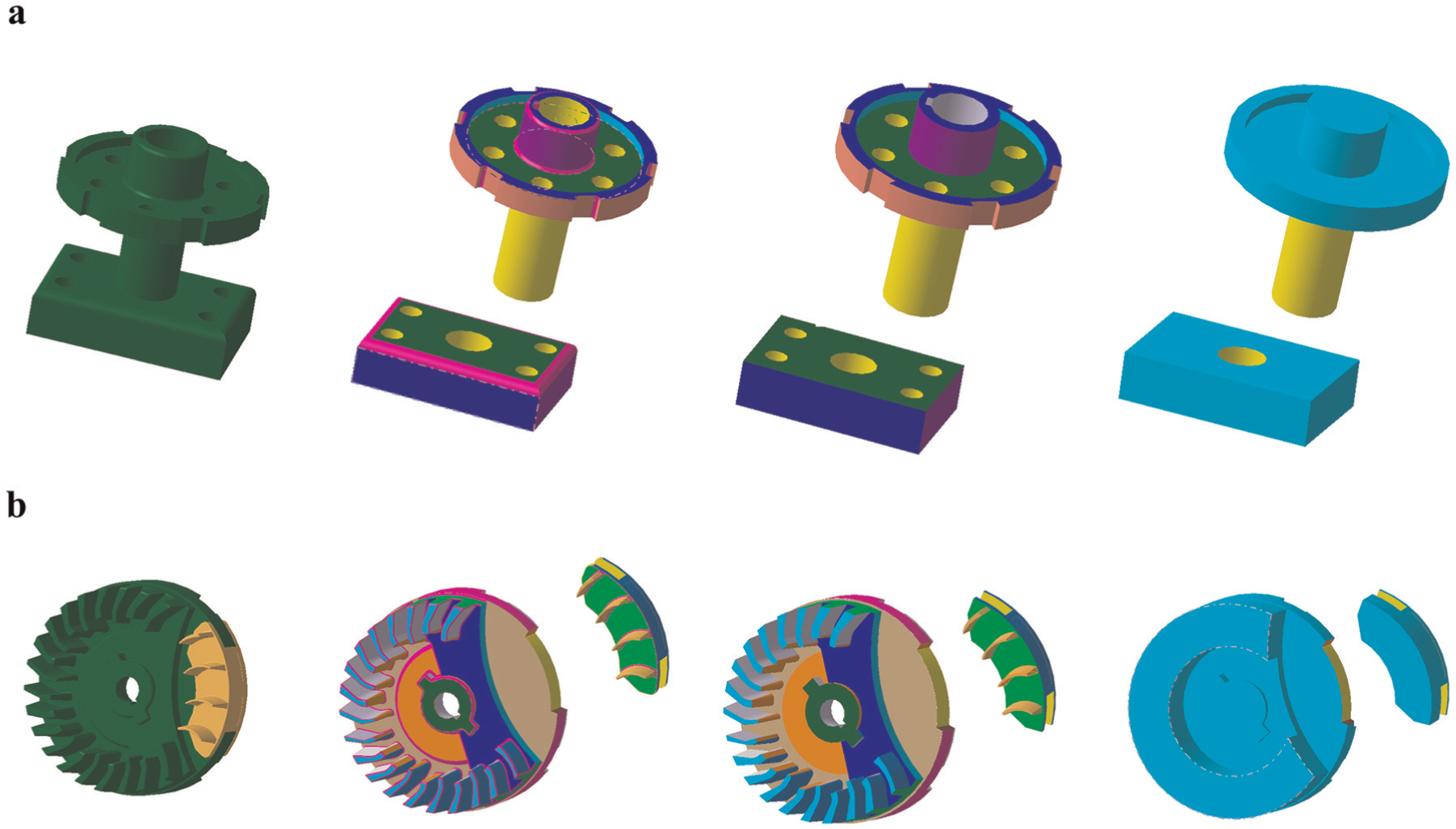
Simplification of different assemblies: (a) assembly 1 and (b) assembly 2.
The performance analysis of assembly features recognition
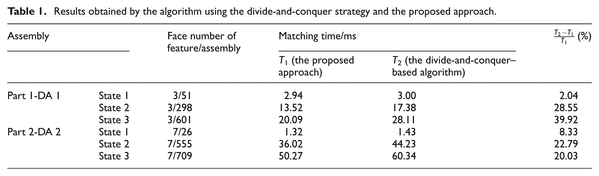
Further experiments and analysis are required to test the efficiency of assembly features recognition method based on MR. Let the AAGs of Feature 1 in Figure 14(a) and Feature 3 in Figure 14(b) be
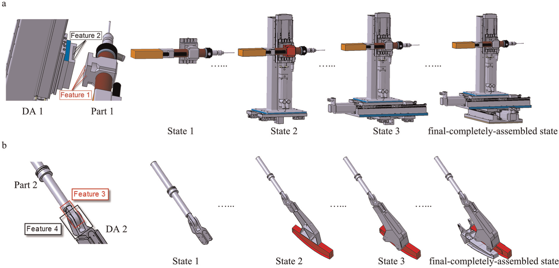
Assembly features recognition: (a) Part 1-DA 1 and (b) Part 2-DA 2.
For the assembly features recognition problem in Figure 14, Table 1 shows the comparison of performances between the algorithm using the divide-and-conquer strategy
27
and the proposed assembly features recognition approach. In order to explore the concrete relationship between the matching time and the complexity of the to-be-matched component (here, it refers to a dynamic assembly), suppose the face number of a given form feature (e.g. Feature 1 or Feature 3) is fixed and progressively increase the face number of the to-be-matched component DA 1 or DA 2 and record the corresponding matching time to find assembly features. The face number of the to-be-matched component increases as it keeps growing to the final-completely-assembled state. As shown in Figure 15, when the face number of the to-be-matched component
Results obtained by the algorithm using the divide-and-conquer strategy and the proposed approach.
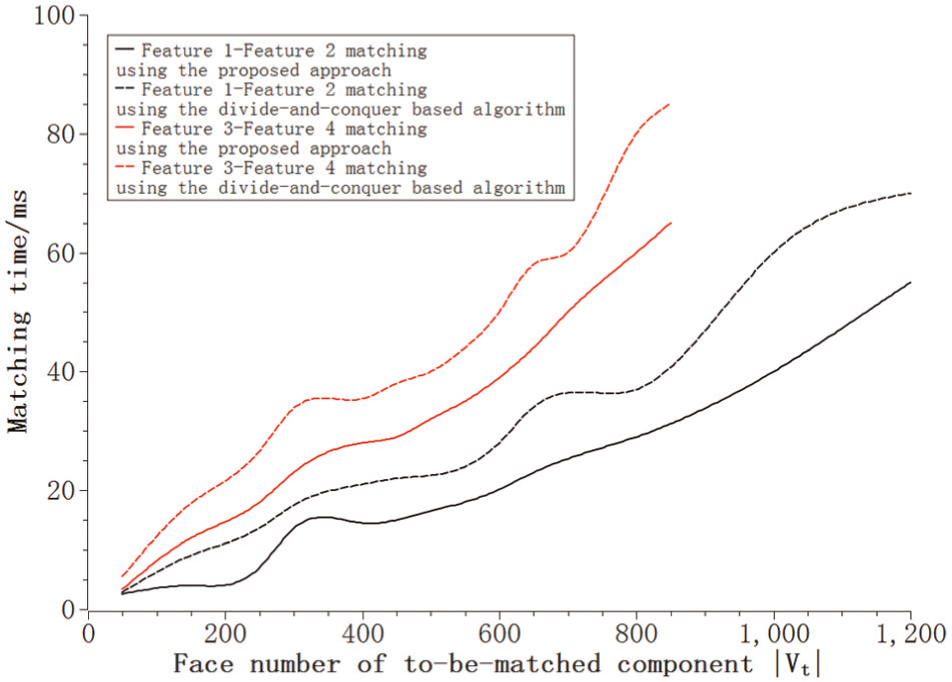
The relationship between the matching time and the complexity of to-be-matched component.
Conclusion
With the purpose of demonstrating and interacting with the virtual assembly process of complex product in real time and delivering the 3D-based assembly process information to assembly field, this article proposes a cloud service architecture for mobile 3D model and a dynamic assembly simplification method in cloud computing environment. The current-assembled-state assembly model is simplified by removing the invisible features while preserving its appearance; the to-be-assembled component model is simplified with assembly features well preserved so that it can complete the assembly process more smoothly in 3D virtual assembly scene. The problem of assembly features recognition is translated into conjugated subgraphs matching. In order to improve the efficiency of conjugated subgraphs matching among the AAG of the currently selected to-be-assembled component, the large-scale AAG corresponding to the current-assembled-state assembly and a large set of small AAGs corresponding to the rest of the to-be-assembled components, a filter algorithm is introduced based on the idea of constraint programming to reduce the search space of the large-scale AAG. Meanwhile, the serial code of conjugated subgraphs matching is parallelized by using MR. Experiments illustrate the superiority of the proposed approach over the algorithm using the divide-and-conquer strategy.
The proposed cloud service architecture for mobile 3D model and dynamic assembly simplification method present a feasible solution for mobile 3D model on assembly field of complex product, which would facilitate the assembly task, shorten the design cycle and reduce the cost.
However, the current research is limited in several ways. First, the goals of all the stakeholders (architecture builder, cloud service users, etc.) of the proposed cloud service architecture are often conflicting. For example, performance of the architecture is the major concern of the end users, while the architecture builder or provider is mostly interested in cost reduction, and these two goals (or concerns) are competing and conflicting. Further work will focus on analyzing the most appropriate trade-offs among goals of stakeholders by using the goal-oriented simulation approach 58 to further refine the detail design (mainly at the infrastructure layer) of the proposed cloud service architecture. Second, more experiments are needed to justify the superiority of the proposed approach. Limited kinds of experimental environments have been established at this stage. And it will be necessary to consider the possibility of adopting the cloud computing simulation tool CloudSim to set up more homogeneous experimental environments.
Footnotes
Declaration of conflicting interests
The authors declare that there is no conflict of interest.
Funding
The authors would like to thank the Basic Research Foundation of Northwestern Polytechnical University (Grant No. JC201137) and National Key Technology R&D Program for financially supporting this research.