
Abstract
In a typical part manufacturing system, machining operations represent a major proportion of the total energy consumption. The energy consumption (in the form of electricity power) of a machining operation can be divided into four types, that is, standby power, operational power, cutting power and power loss due to cutting load. Power loss due to cutting load includes the power loss caused by the friction of mechanical transmission and the power lost in the motor when the cutting load is applied to the spindle system. While the first three types of power consumption have been studied intensively by previous researchers, the power loss due to cutting load, which accounts for up to 20% of the cutting power consumption during machining operations, has received relatively less attention. This article proposes a novel model to characterize power loss due to cutting load, in which the power lost in the mechanical transmission and in the spindle motor are analyzed and modeled separately. Cutting tests have been carried out to validate the proposed model using two numerical control lathe machines. And a method has been developed for reducing energy loss caused by cutting load, which includes cutting force prediction, power loss due to cutting load prediction and decision making. The method was evaluated through its application in the process design for a shaft part, and the results show a significant saving of up to 70.8% of energy loss caused by cutting load.
Introduction
The increased use of energy has led to serious environmental concerns, including resource issues and global warming. Industrial sectors represent one-third of the total energy consumption in the United States. 1 Machine tools and manufacturing systems are widely used in various industries, accounted for a significant proportion of electricity use in industry.2,3 To develop more energy-efficient machine tools, designers and manufacturers need to better understand how energy is consumed in machining operations, and methods for modeling energy consumption of machining operations would help engineers better understand and analyze the causes so as to reduce energy consumption of machine tools.
As shown in Figure 1, the electric power consumption during machining can be divided into four types: standby power (when the machine tool is in standby status while the spindle is turning), operational power (power used to enable spindle rotation, feed axis movement, coolant pump spraying, tool change, etc.), cutting power and power loss due to cutting load (PLCL). 4 The four types of power have been studied by previous researchers, such as the investigation into fixed power, 5 modeling of spindle acceleration power, 6 cutting power 7 and the acquisition of loading loss coefficient of main driving system. 8 PLCL is defined as the power loss caused by cutting load applied to the spindle system. It is the difference between the increased power due to cutting operation and the power used to overcome the cutting forces for chip formation. When a load is applied to the spindle, the spindle motor will overcome not only the cutting load, but also the load-related loss. The load loss includes the energy loss caused by the friction of the mechanical transmission system and the loss within the motor itself caused by the cutting load. 9 Predicting PLCL is important for energy saving. However, there is still lack of understanding of PLCL due to its inherent complexity.
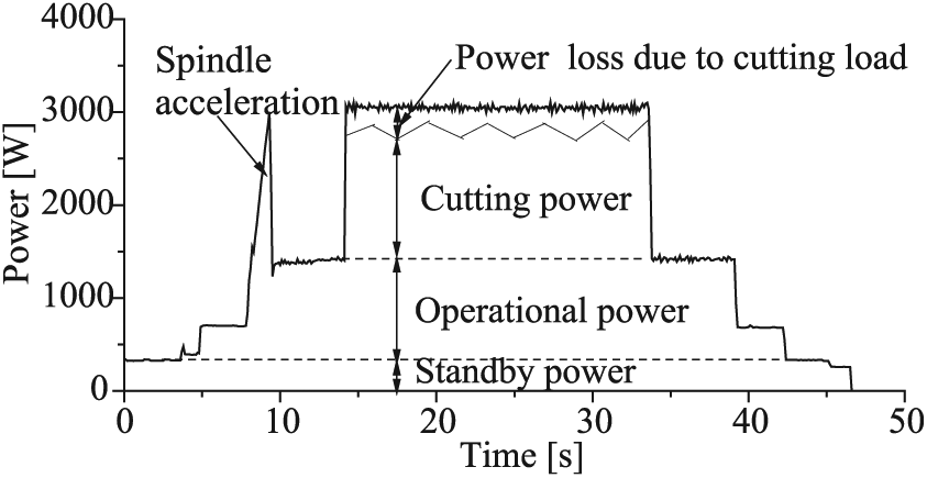
The electric power decomposition during a typical machining operation.
In the late 1950s, a large amount of experiments were carried out in the Soviet Union to study the energy efficiency of machine tools. 10 Results showed that PLCL was relatively a large proportion of the total energy consumption at lower speed and under heavier cutting load, while it is relatively a small proportion at higher speed and in lighter load condition. Take the 1A62Mlath as an example, the ratio of PLCL to the total power of machining was reduced from 12% (spindle running at 93 r/min) to 6% (spindle running at 590 r/min). In the 1990s, PLCL of manual lathes was investigated and reported to be proportional to the cutting load, and the ratio of PLCL to cutting load was between 15% and 20%. 11 Li and Kara 4 indicated that PLCL, called unproductive energy by them, was generated by the friction created at the bearings and mechanical transmission system. Later, Hu et al. 9 modeled PLCL as a quadratic function of cutting load based on electrical motor theory. In their study, the power lost in the mechanical transmission due to cutting load (PLMT) was assumed to be proportional to the cutting load without explanation or how the formula was derived. Moreover, the quotient of motor load and slip was assumed to be constant for all ranges of motor speeds. However, the above two assumptions do not hold true for numerical control (NC) machining processes.
PLMT is mainly converted into heat due to friction in the spindle bearings. 12 The loss of energy due to friction in bearings is influenced by the spindle rotational speed, the diameter of the bearing and the radial and axial loads. 13 The cutting load is the product of the spindle angular speed, the cutting force and the radius of the workpiece. It can be inferred that PLMT is independent of the workpiece radius and cannot simply be assumed to be proportional to the cutting load. Additionally, as the spindle motor is driven by variable voltage variable frequency (VVVF) inverter, the quotient of motor load and slip K1 could vary with different motor speeds. The motor speed range below base speed is that of a constant-torque drive. Here, the base speed is the motor nameplate rated speed when the motor is operating at base frequency (usually 50 or 60 Hz depending on different countries). As the electrical frequency decreases, a given value of torque corresponds to a larger slip and lower motor load. 14 Thus, K1 may decrease as inverter frequency decreases. Ignoring these two facets, previously developed models failed to provide a realistic analysis result for the additional load loss.
This article presents a novel model to characterize the non-productive load loss PLCL of machine tool spindle system. The difficulty of the modeling work lies that PLCL involves cutting load, mechanical transmission and motor, which make it an electromechanical coupling problem. A method for reducing energy loss due to cutting load has been developed by the authors, which can be used by machine tool designers, machining process designers and machine tool operators for energy saving purposes.
Section “Model development” describes the model of PLCL based on power loss of rolling bearing and spindle motor loss for computer numerical control (CNC) lathe machines. Section “Experiments and model validation” describes the design of experiments and the proposed model is validated based on the measured power. Section “Method for reducing energy loss due to cutting load” describes the method for reducing the energy loss caused by cutting load (ELCL). Section “Case study” demonstrates the effectiveness of the proposed method. In section “Conclusion,” the conclusions are drawn and future work is discussed.
Model development
PLCL consists of two parts: PLMT and power lost in the spindle motor (PLSM). These two components of power loss are modeled separately. Ball bearings or cylindrical roller bearings are generally used to support a spindle, and induction motors are most commonly used to drive a spindle. Without loss of generality, the models of PLMT and PLSM were developed based on a spindle equipped with ball or cylindrical roller bearings and an induction motor.
Power loss in mechanical transmission due to cutting load
The power loss in mechanical transmission is mainly caused by the friction between gears, bearings and pulleys. For NC machines, the loss in bearings dominates the total mechanical loss in the spindle system. 12 Thus, PLMT is computed by subtracting the power loss caused by bearing friction during air-cutting (non-cutting movement of spindle) from that during normal cutting (material cutting). The power loss caused by bearing friction consists of three elements: load friction torque M1, viscous friction torque and friction torque due to roller end motions against the flanges Mf. 13 The viscous friction torque is independent of load, while M1 and Mf depend on load. As a result, PLMT is calculated from M1 and Mf under air-cutting and normal cutting conditions. Related formulas of M1 and Mf can be found from Harris and Kotzalas 13 and Palmgren. 15 By integrating cutting force into the bearing power loss formulas, PLMT caused by load friction torque M1 can be expressed as
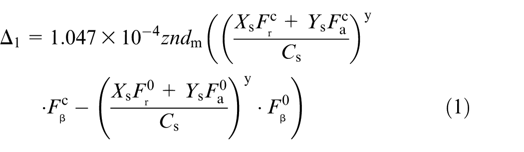
where z, y, Xs and Ys are related coefficients that depend on the ball bearing type and nominal contact angle; n is spindle speed (r/min); dm is the mean diameter of the bearing (mm); Cs is the basic static load, whose value is generally given in manufacturers’ catalogs;

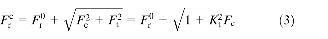
where Kt and Kf are related coefficients,

Then the difference of power loss given by equation (1) becomes
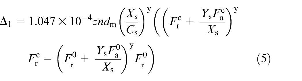
We substitute equations (3) and (4) into equation (5) and then Taylor expand the function f(x) = (1 + x)a around x = 0, leading to f(x) = 1 + ax +a(a –1)x2/2 + O(x3), where O(x3) represents the summation of high order terms. With this linearized form for f(x), the terms higher than first order can be neglected, we have
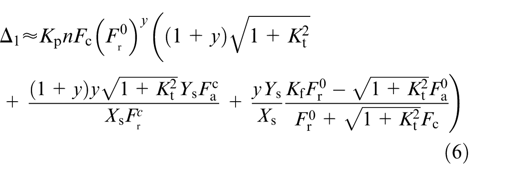
where


As a result, equation (6) can be expressed as
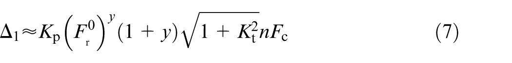
PLMT caused by Mf is described as a function of speed

where ff is a factor associated with bearing type and lubrication. The difference of the power loss due to this sliding friction is
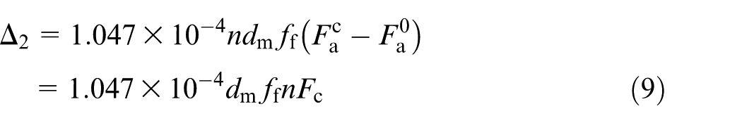
Equations (7) and (9) indicate that PLMT is proportional to the primary cutting force and spindle speed, expressed as

where bm is a constant coefficient.
Power loss in the spindle motor due to cutting load
The power loss in the spindle motor includes two types: the fixed losses and variable losses. The fixed losses are independent of cutting load on motor, while the variable losses depend on the load. Therefore, PLSM can be calculated from the difference between the variable losses under normal cutting and under air-cutting conditions. The variable losses consist of losses caused by stator and rotor resistance and stray load losses. The losses caused by stator and rotor are proportional to the resistance of the material and the square of the current, while stray load losses are generally proportional to the square of the rotor current. 18 Using the equivalent circuit for induction motor, 19 the variable losses can be expresses as
where R1 is the stator effective resistance (Ω), R2 is the rotor effective resistance (Ω), Kst is the coefficient (W/A2) of stray load losses, Pc is cutting power (W), Pum is the power of mechanical transmission (W) without load, Pam is the power loss in mechanical transmission due to cutting load (W), Tm is the electromechanical torque (N m), ωm is the mechanical angular velocity of the motor (rad/s), ωs is the synchronous angular velocity of the motor (rad/s) and Δω = ωs – ωm is the difference between the synchronous and mechanical angular velocities of the motor. Tm varies with the load and is determined by the magnetic flux of the motor. The flux density is proportional to the quotient of stator voltage and frequency of the input voltage. From minimum frequency, the voltage is adjusted proportional to frequency. The flux is kept constant up to the base frequency. From the base frequency upward, the voltage keeps constant at its rated value. 20 The flux is reduced and the motor enters the field weakening region. Therefore, Tm is modeled in two cases.
Below the base frequency, the spindle motor is running below base speed, the motor voltage varies with respect to the frequency, Tm would be 14
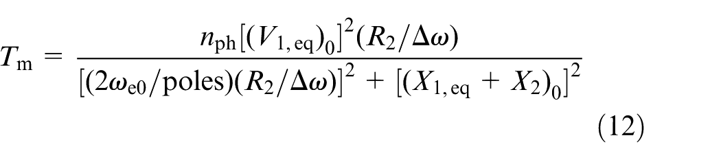
where nph is the number of stator phases, V1,eq is the equivalent stator line-to-neutral terminal voltage (V), X1,eq is the equivalent stator leakage reactance (Ω) and X2 is rotor leakage reactance (Ω). The subscript 0 represents rated frequency values of each of the induction motor parameters. In this case, the frequency f is lower than the rated frequency; thus, the excitation frequency ωe < ωe0, [(X1,eq + X2)0]2 ≪ [(2ωe0/poles)(R2/Δω)]2, can be neglected in the denominator. Making appropriate approximations, equation (12) can be reduced to
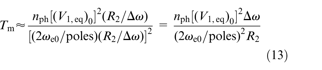
By substituting equation (13) into equation (11), it can be obtained
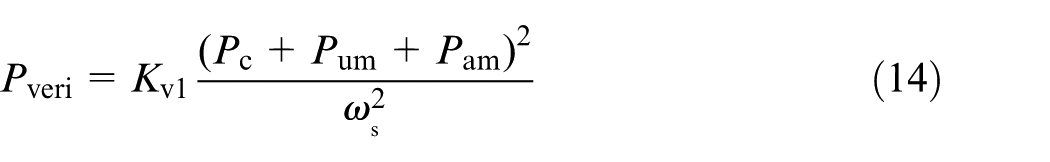
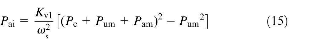
where Kv1=(R1+R2+Kst)(2ωe0/poles)2nph−1[(V1,eq)0]−2 is a constant coefficient. When no cutting load is applied to the spindle, Pc = Pam = 0. PLSM is determined by the difference in the variable losses due to the cutting load
Above the base frequency, the motor is running above the base speed; the motor voltage is kept at the rated value. Tm can be written as
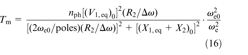
Similarly, [(X1,eq + X2)0]2 is much less than [(2ωe0/poles)(R2/Δω)]2 and can be neglected in the denominator; equation (16) can be reduced to
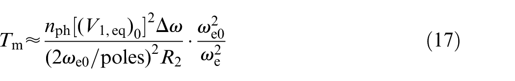
In the above equation, the electrical excitation frequency ωe is proportional to the synchronous angular velocity of the motor ωs, which is expressed as
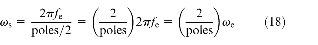
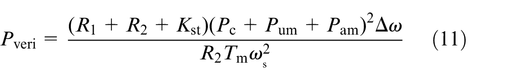
Substituting equations (17) and (18) into equation (11) gives

where Kv2 = (R1 + R2 + Kst) nph−1 [(V1,eq)0]−2 is a constant coefficient. In this case, PLSM is calculated as

Power loss in the spindle system due to cutting load
The total PLCL is expressed as

When the spindle motor is operating below the base speed, substituting equations (10) and (15) into equation (21) gives
For turning operation, the cutting power is calculated as
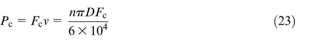
where v is the cutting speed (m/s) and D is the diameter of the workpiece (mm). The relationship between synchronous angular velocity of the motor ωs and spindle speed n is expressed as
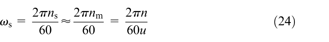
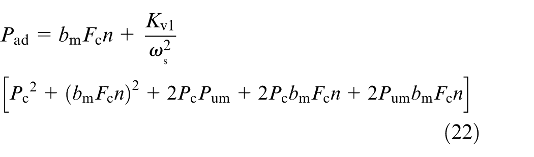
where u is the transmission ratio of the spindle shaft to the spindle motor. Substituting equations (23) and (24) into equation (22) gives
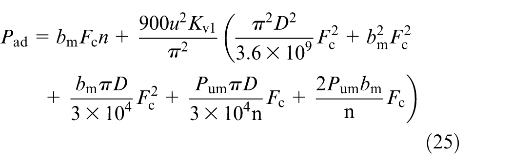
When the spindle motor is operating above the base speed, substituting equations (10), (20) and (23) into equation (21) gives
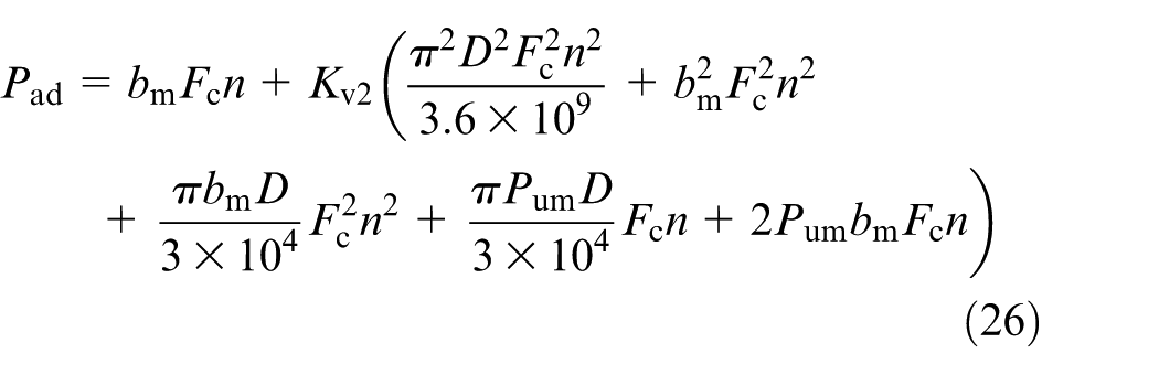
From the above equations, it can be observed that PLCL is a quadratic function of the cutting force. The diameter of the workpiece would positively influence PLSM, but not PLMT. In the case of the spindle motor running below the base speed, the spindle rotational speed would positively influence PLMT, while negatively affect PLSM. Above the base speed, PLCL could be expressed as a quadratic function of spindle rotational speed. This observation is important because, if the turning processes are conducted with spindle motor speed running below the base speed as in most cases, it can be expected that PLCL is mainly affected by the cutting force. As a result, PLCL mainly increases with the cutting force. In the following sections, experimental evidences are provided to support these observations.
Experiments and model validation
Experimental setup
The experiments were conducted on two NC lathes (CK6153i and CK6136i) which were made by Jinan First Machine Tool Group Co., Ltd., China. The spindles of both lathes are driven by three-phase squirrel-cage induction motors and supported by rolling bearings. The spindle speeds are calculated to be 1042 and 1076 r/min when the spindle motor is running at the base speed of 1500 r/min for CK6153i and CK6136i, respectively. During the turning process, the spindle speed is usually running below 1042 r/min to avoid increasing tool wear due to high cutting speed. Thus, the spindle motor is usually running below the base speed. The cutting tests were conducted with different cutting parameters to investigate the factors that influence PLCL.
Three different types of workpiece materials, including AISI 1045 steel, AISI 6061 aluminum and AISI 80-55-06 ductile iron, were selected to perform cutting experiments under dry conditions. The initial size of the workpiece is Φ80 mm × 150 mm. The turning experiments were performed with TiCN-coated carbide inserts (VNMG160408N-UX-AC820) for steel and ductile iron, and uncoated carbide inserts (CCGT09T304-AK-H01) for aluminum. During the machining process, the cutting force and electrical power consumption were measured using a three-component force dynamometer (Kistler Type 9257A) and a power measurement device. The experimental setup is shown in Figure 2. An example of measured cutting force and power was shown in Figure 3. PLCL was identified by subtracting power consumption when the machine is idle and cutting power which is used through the tool tip for material removal from the power consumption of the machine tool during normal cutting Pin, as shown in equation (27)

where P0 is the measured power during air-cutting and Pm is the material removal power.
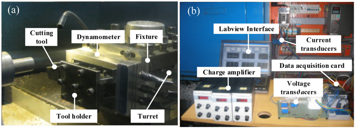
Experimental setup: (a) cutting force dynamometer and (b) power measurement device.
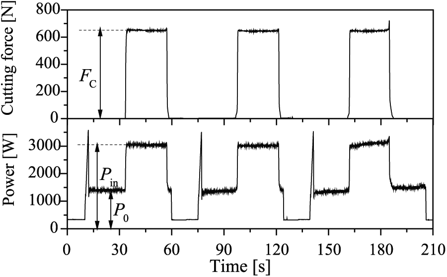
An example of measured force and power of CK6153i in the machining experiments. Workpiece material: steel; cutting speed: 150 m/min; feed: 0.1 mm/rev; depth of cut: 2.0 mm.
Experimental design
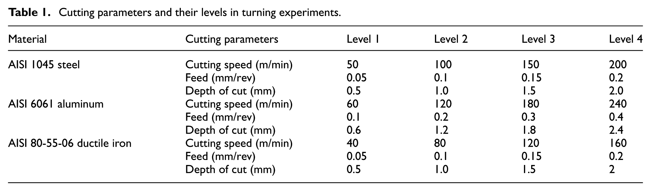
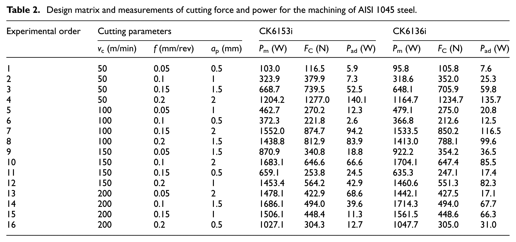
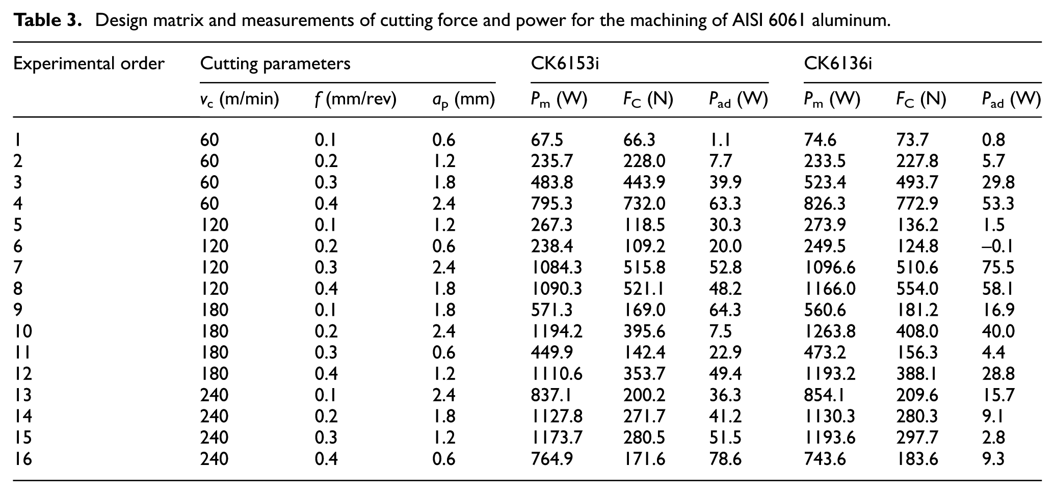
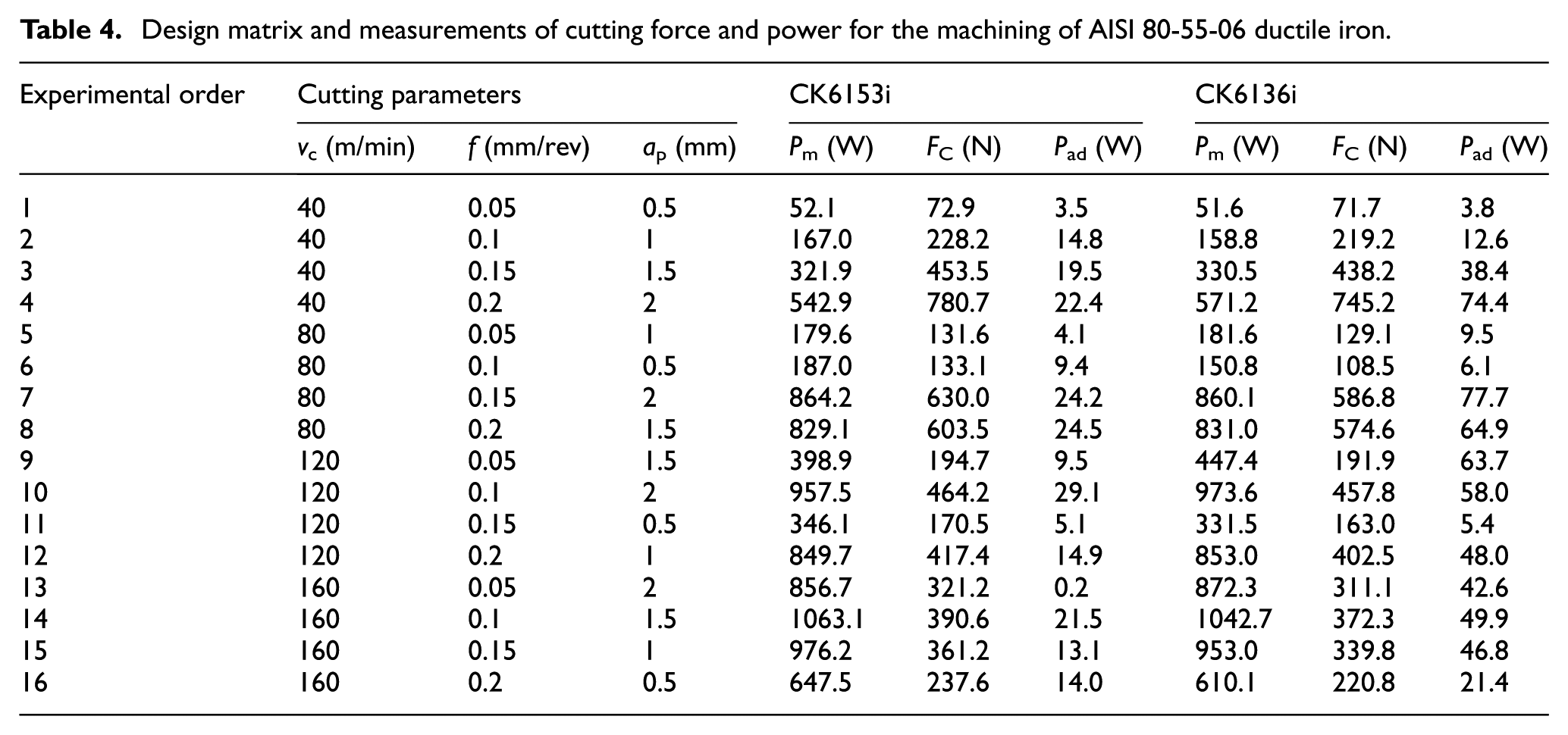
Different parameters were used in the cutting experiments. Parameters, including cutting speed v, feed f and depth of cut ap, and their ranges were selected as tool manufacturer’s recommendation. The values are shown in Table 1. For the machining experiments of each material, Taguchi’s orthogonal design L16 (34) was employed, and 16 experiments were conducted for turning processes of each material in dry condition (without using cutting fluid). The length of cut for each test was 30 mm in axial direction. The response variables are the primary cutting forces and the total power consumption of the machine tool. Each run of the experiment was repeated three times and the average values of the three calculation results of PLCL were used in this article. The experimental design and measurements of cutting force and power are shown in Tables 2–4.
Cutting parameters and their levels in turning experiments.
Design matrix and measurements of cutting force and power for the machining of AISI 1045 steel.
Design matrix and measurements of cutting force and power for the machining of AISI 6061 aluminum.
Design matrix and measurements of cutting force and power for the machining of AISI 80-55-06 ductile iron.
Model validation
In this section, models are validated for the two NC lathes, when spindle motor is running below the base speed. As shown in Figure 4, there is a positive relationship between PLCL and cutting power. However, PLCL does not strictly increase with the cutting power. According to the model proposed by Hu et al., 9 PLCL can be fitted by second-order polynomial regression of the cutting power. The fitted models are shown in Table 5. The R-square values of the two models are less than 0.74, which shows that PLCL cannot be accurately predicted using the quadratic function of cutting power.
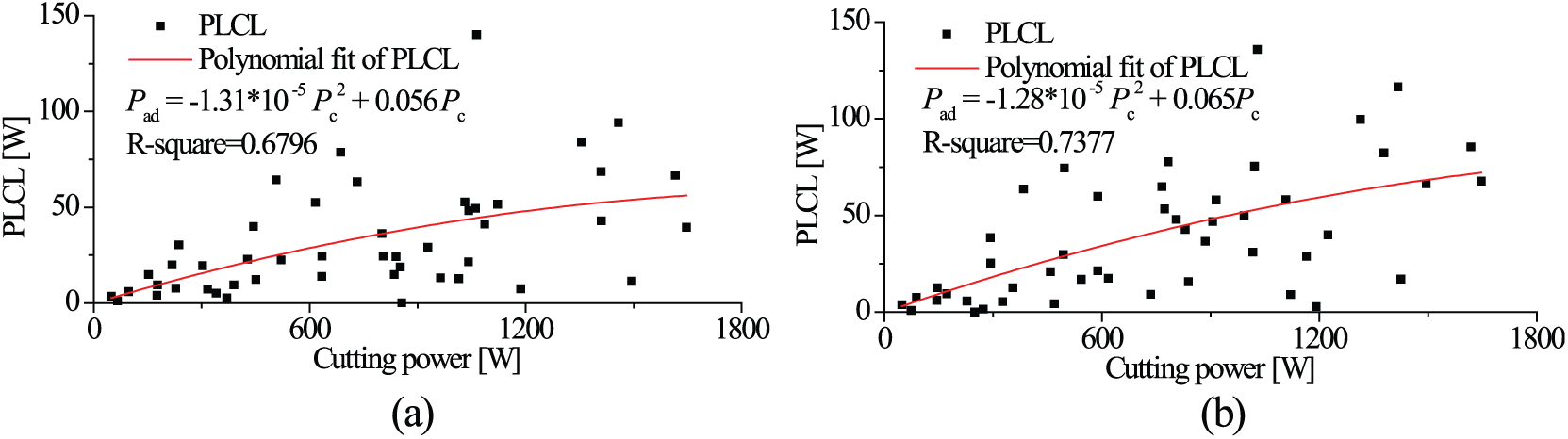
Measured PLCL with respect to cutting power: (a) CK6153i and (b) CK6136i.
PLCL models as a quadratic function of cutting power.
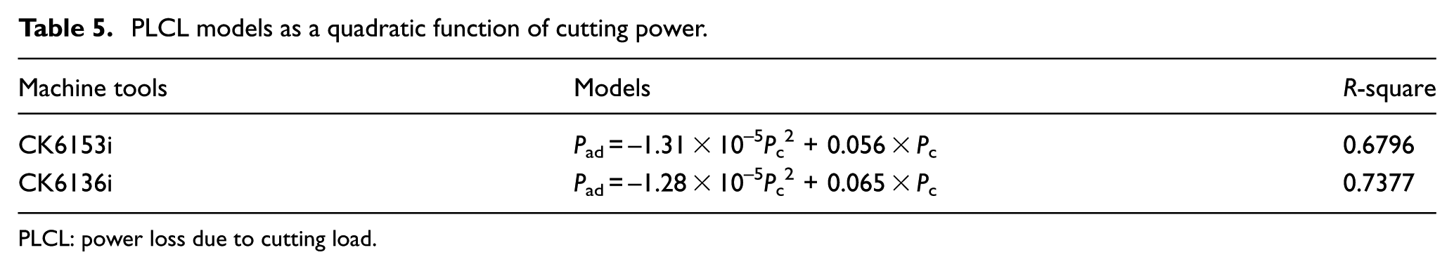
PLCL: power loss due to cutting load.
Regression analysis is used to fit the PLCL as a quadratic function of cutting forces (see Figure 5). In Figure 5(a), several data points lie far from the regression line, which could be explained by the small values of PLCL being largely influenced by power fluctuations of CK6153i and measurement errors. Overall, the data points are less scattered than those in Figure 4, which indicates that PLCL is more influenced by the cutting force than the cutting power. The fitted models are summarized in Table 6. The R-square values have increased a lot, from 0.6796 to 0.7756 for CK6153i lathe and from 0.7377 to 0.9129 for CK6136i lathe. These results indicate that the cutting force based model is more suitable to describe PLCL than the power-based model when the spindle is running below the base speed, which agrees with the theoretical model developed in equation (25).
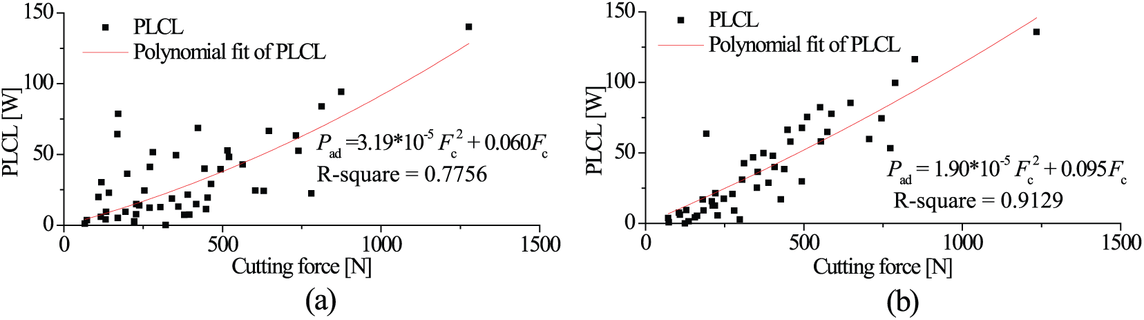
Relationship between the PLCL and the cutting forces: (a) CK6153i and (b) CK6136i.
PLCL models as a quadratic function of cutting force.
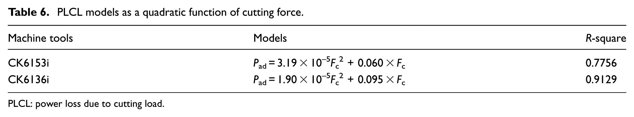
PLCL: power loss due to cutting load.
When spindle motor is running above the base speed, substituting equations (23) into equation (26) gives
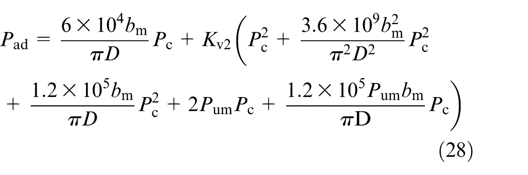
Equation (28) shows that when spindle motor is running above the base speed, PLCL is a quadratic function of cutting power, which agrees with the model proposed by Hu et al. 9 It can be inferred that the cutting power-based model is appropriate to describe the additional load loss when the spindle is running above the base speed.
PLCL is caused by cutting power which is used for workpiece surface generation. It is wasted and dissipated to environment in the form of heat. Here, the ratio of PLCL to cutting power, which is defined as the load loss coefficient Cad, is introduced to measure the energy efficiency. Smaller coefficient means less energy is wasted by the spindle system during machining. The average values of additional load loss coefficients are 4.72% and 5.45% for CK6153i and CK6136i, respectively. These values are much smaller than that reported by Liu et al. 21 This could be explained by the spindle mechanical transmission chain being shorter and less energy being consumed due to mechanical loss for CNC machine tool compared to manual machines.
The non-productive load loss is ultimately converted into heat, which is largely absorbed by the mechanical transmission system and the spindle motor. Too much heat could cause extra thermal deformation of the components in the spindle system, such as spindle and chuck. This would increase thermal errors and affect the machining accuracy. From this perspective, the machine tool should not work continuously for a long time (over 60 min for instance) with heavy load or high cutting power to avoid heat accumulation and the associated thermal error.
Method for reducing energy loss due to cutting load
The above results indicate that PLCL varies with cutting force; thus, PLCL can be reduced while retaining the production efficiency by proper selection of machine tools and cutting parameters in the process design phase. The method for reducing ELCL consists of three steps including determination of cutting force model, determination of PLCL model and decision making for energy reduction, as shown in Figure 6.
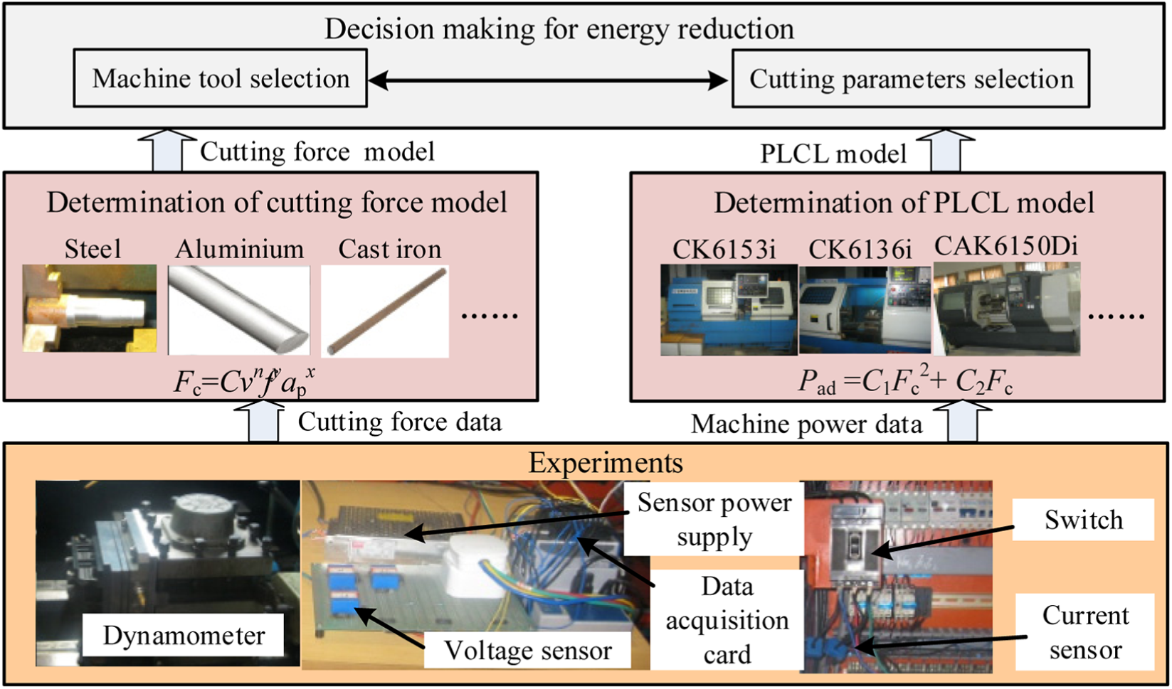
Method for reducing energy loss due to cutting load.
Determination of cutting force model
The cutting force is very difficult to model accurately due to the complexity of the metal cutting mechanics. For convenience, a generic exponential model is usually used to describe the relationship between cutting force and cutting parameters 22

where
Based on the above linear equation, the unknown coefficients
Determination of PLCL model
The theoretical model of PLCL is complex and there are many coefficients in the model which are hard to obtain. As shown in equations (25) and (26), PLCL can be considered as a quadratic function of cutting force or cutting power. Therefore, the PLCL model can be obtained experimentally. In the cutting tests, cutting parameters are selected as independent variables while cutting force and power consumption of the machine tool are dependent variables. The value of cutting power and PLCL can be calculated using equations (23) and (27). Then coefficients in the PLCL model are obtained by quadratic regression analysis of experimental data.
For each model of machine tool, the PLCL model should be obtained separately. When the cutting force and PLCL models are obtained, they can be stored in database and support decision making to reduce ELCL.
Decision making for energy reduction
The reduction of ELCL can be supported by decision-making method during process design stage. Such method includes two steps: (1) ELCL prediction and (2) cutting parameters and machine tool selection. ELCL is determined by multiplying PLCL and machining time. Usually several process plans can be designed before machining. Based on the process information (such as workpiece material, machine tool and cutting parameters), developed models and database, PLCL and related machining time can be calculated. With the predicted values of ELCL, process designers can compare and analyze the ELCL of different potential process plans. Then cutting parameters and machine tool which could lead to minimum ELCL can be selected to support energy-efficient machining.
Case study
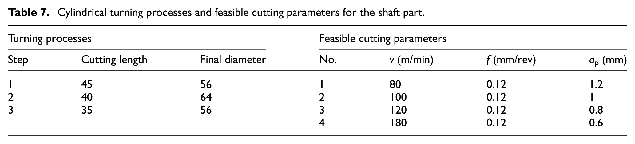
This section describes the application of the proposed method for machining a shaft part. In this case study, a cylindrical steel workpiece with a diameter of 100 mm is machined into a shaft part which is used in steam turbine, as shown in Figure 7. Two NC lathes, namely CK6153i and CK6136i as shown in section “Experimental setup,” were used for machining. The cylindrical turning processes and feasible combinations of cutting parameters suggested by machine tool operators are shown in Table 7.
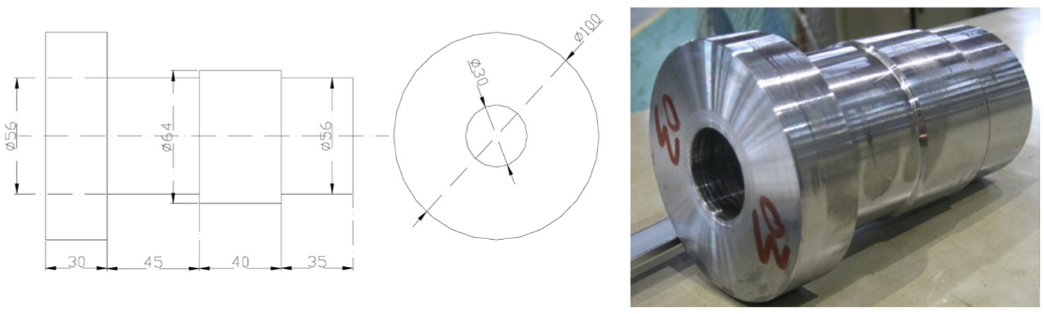
The shaft part used for the case study.
Cylindrical turning processes and feasible cutting parameters for the shaft part.
Based on equation (30) and data in Table 2, cutting force model is acquired by multiple linear regression analysis of measured cutting force, as shown in equation (31)

Formulas of PLCL are from Table 6. The number of cuts N and machining time for each cut tm (s) can be calculated using equations (32) and (33)


where Di and Df are initial and final diameter of machined part, Lm is cutting length (mm) and n is spindle rotational speed (r/min). The total ELCL Ead (W) is calculated as
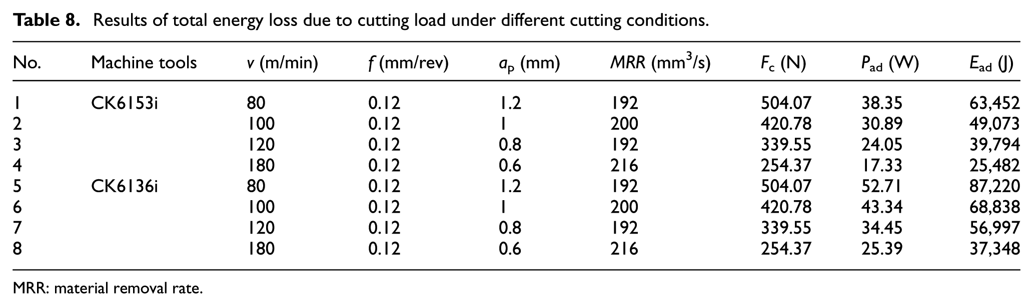
where m is the number of steps in the machining process. Results indicate that less ELCL is consumed when the machine tool is running at higher speed than at lower speed with similar material removal rates (see Table 8). In this case, process operators can easily select cuttings parameters of group no. 4. When more than one machine tool is available, the machine with lower PLCL (CK6153i in this case) can be selected. A big potential lie in the energy saving of ELCL, which indicates that up to 70.8% of the ELCL can be saved by proper selection of cutting parameters and machines.
Results of total energy loss due to cutting load under different cutting conditions.
MRR: material removal rate.
The energy loss model and reduction method reported in this article play a significant role in machine tool energy prediction and energy efficiency improvement. Traditionally, the process parameters and machines are usually selected based on experience of the process designer, ignoring the energy issues. With the developed method, process designers can predict and compare ELCL of different feasible process design options before starting the actual machining. Then process parameters and machine tool can be selected to reduce the ELCL during machining.
Additionally, if the power consumption of the machine tool and cutting force is monitored during machining, the value of PLCL can be obtained and used to diagnose the health condition of the spindle system. If the measured PLCL is significantly larger than the predicted value, or increases a lot suddenly during operation, it means that some components may not match well with each other or have worn out due to increased friction; thus, the spindle system needs maintenance.
Conclusion
PLCL is an important element of power consumption of machining operations. The energy modeling of this element could provide the basis for the analysis and reduction of energy consumption. In this article, a novel model of PLCL for the spindle system of NC lathes has been developed based on the analysis of the energy loss in the mechanical transmission system and the spindle motor. Experiments were conducted to validate the effectiveness of the proposed model on two NC lathes. Method for reducing this element of energy loss was developed. Based on the theoretical and experimental investigation, some conclusions can be drawn:
PLCL is approximately expressed as a quadratic function of cutting force when spindle motor is running below the base speed. In this case, there is a positive relationship between PLCL and cutting force. PLCL is approximately a quadratic function of cutting power when spindle motor is running above base speed.
Machine tools consume much less ELCL when running at higher speed than at lower speed with similar material removal rate.
The developed method could significantly reduce ELCL (up to 70.8%) by the proper selection of process parameters and machine tools in the process design stage.
The proposed model can provide a more accurate estimation of PLCL, which will be useful for the reduction of this part of energy in process design phase. This research also implies that the value of PLCL can be adopted as an indicator for fault diagnosis of the spindle system of machine tools. Further research will be conducted to test and apply the developed model and method for other types of machine tools, such as milling, drilling and grinding machines.
Footnotes
Appendix 1
Acknowledgements
The authors would like to convey their sincere thanks to Mr Yang Kaidong from Tsinghua University, Mr Shao Saijun from the University of Hong Kong, Prof. Zhou Jilie and Mr Wang Qiang from the metalworking center of Zhejiang University for their valuable contributions during the experiments.
Declaration of conflicting interests
The author(s) declared no potential conflicts of interest with respect to the research, authorship and/or publication of this article.
Funding
The author(s) disclosed receipt of the following financial support for the research, authorship, and/or publication of this article: This work was supported by the National Natural Science Foundation of China (Grant Nos. 51705428, U1501248) and the International Clean Energy Talent Program of China Scholarship Council (Liujinfa[2017]5047).