
Abstract
A computational procedure for the calculation of the material parameters involved in the structural design of multi-material components is presented. The developed scheme can be used in the design process for the full or partial replacement of a metallic part with a metal/fiber–reinforced composite bi-material, aiming at weight savings. Finite element simulations are incorporated into an algorithm that rapidly reduces the design space until a good set of design variables has been reached. The process is controlled by two objective functions (mass and strain energy minimization) and is subjected to several constraints according to the component’s design requirements. Three examples have been adopted to demonstrate the effectiveness of the approach. The results show that the upper limit for weight reduction is constrained by the yield strength of the metal component and therefore its corresponding thickness. Based on the design configuration, weight savings up to 25% could be reached.
Keywords
Introduction
The design optimization for weight savings and performance of structural components produced by metallic materials has attained a high maturity level over the last decade. 1 Further weight reductions can be performed by combining fiber-reinforced polymer (FRP) materials with metals in order to produce hybrid multi-material components. FRPs may be bonded on selected locations of the metallic component’s area and reinforce certain material directions while weighting much less (density of steel is 7850 kg/m3 and density of carbon FRP is 1800 kg/m3) and at the same time satisfy the imposed design requirements. 2 Particular focus has been given in the automotive industry by redesigning the traditional metallic B-pillar component with a hybrid metal/composite multi-material, as shown in Figure 1.

Composite-metal hybrid B-pillar parts of body in white in automotive applications.
Until recently, the manufacturing of such hybrid parts was hampered by the dissimilar material joining challenges and the inability of the composite part to be manufactured in a massive and automated way. Recent advances in manufacturing chains (see for example Figure 2) have enabled the fully automated production of hybrid parts with high flexibility and optimized mechanical properties.5–10 In most hybrid part production methods, the FRP material is either directly bonded to the metal substrate through its resin matrix material, creating hence a so-called resin-rich layer (RRL), or through a separate adhesive layer. The hybrid material may be produced in flat panels before its forming to its net shape or by directly depositing FRP layers on the formed net shape of the metallic component. 10 Concerning the problem of the dissimilar joining, the use of thermoplastic composites and adhesives constitutes a practical solution, due to their low price and their disassembly capabilities. Furthermore, this type of joining leads to rigid, sealed and isolated unions 11 and fewer components are required in comparison to other joining methods.
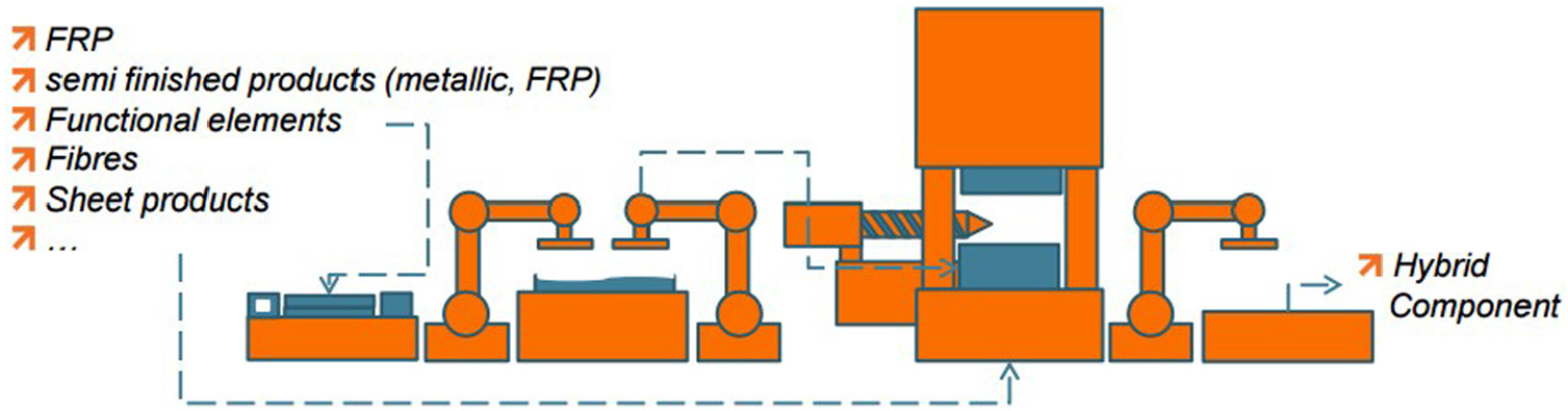
Process chain concept from FormHand that is designed to produce hybrid components.
A multi-stage manufacturing process is under development within the context of ComMUnion project. 10 The concept involves laser texturing of the metallic surface of the component’s net shape, so as to promote adhesion, followed by the lay-up of carbon fiber–reinforced thermoplastic (CFRT) in selected areas by employing the automated tape laying (ATL) technique. 7 The composite material will be joined to the metal component through bonding mechanisms. A first attempt to develop a platform that intends to assist with the design of a hybrid component, alongside with the process planning of its related manufacturing processes, is given in Foteinopoulos et al. 12 The use of computer-aided process planning (CAPP) helps with the establishment of connections between design and manufacturing 13 and will increase the effectiveness of the decision making, both in design and in manufacturing.
Alongside with research on manufacturing methods and consequent process chains for the production of hybrid components, there is a need to develop methods and techniques able to support the design phase of hybrid multi-material components. Conventional design techniques involve trial-and-error design loops in order to satisfy the design and manufacturing requirements. Such approaches are time inefficient and do not certify that the optimal multi-material and geometry configuration will be obtained, with respect to material utilization and weight savings.
The “mechanical design” module, as shown in Figure 3 and in particular, the optimization framework is the focus of this article. The main task of the module is to provide a framework for the calculation of the design variables for the minimization of the component’s weight while assuring the satisfaction of the design requirements. Considering a reference metallic geometry that will be redesigned to be produced with a hybrid multi-material, the associated design variables are the new reduced metal thickness, the number of composite layers and the corresponding layer orientation.
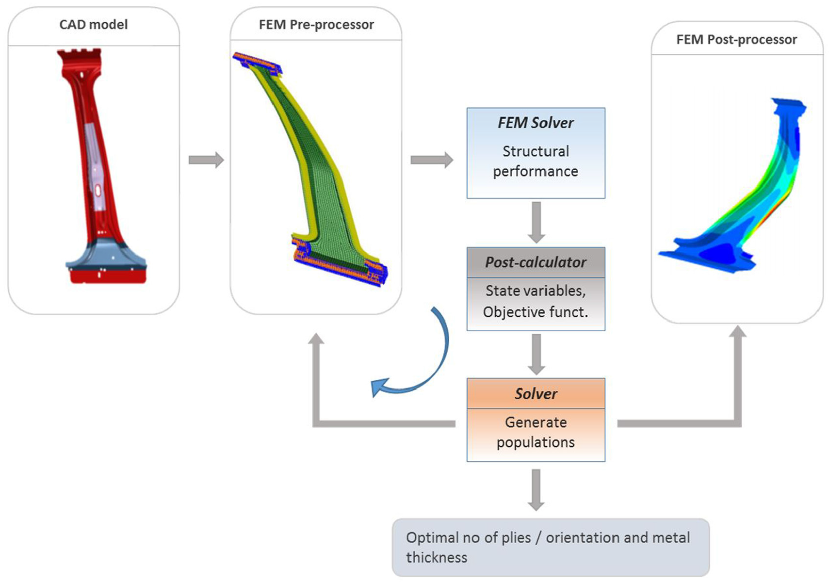
Mechanical design approach for hybrid components.
Optimization techniques are valuable numerical tools that when incorporated in the design phase of structural components, the optimal design variables may be efficiently calculated.14–17 Topology optimization for components produced from laminated composites, metals or other materials involves the calculation of the optimal geometry that weights the minimum possible and utilizes the material in the most efficient way.18,19 In the case of hybrid components, where the constituent materials are characterized by a different structural response (the metal is isotropic and elastoplastic whereas common FRPs are anisotropic and elastic until fracture), relevant work on optimization methods is not found in the scientific literature. Nevertheless, there do exist several research studies on material optimization of “hybrid” (the term “hybrid” in composites is used here to denote a laminate that includes plies with different fiber materials, that is, carbon, glass and Kevlar) laminated composites that develop or/and apply optimization methods for calculating the optimal number of layers and layer fiber orientation associated with the design of a FRP component20–26 but do not account in their formulation the existence of metallic plies.
Four categories are commonly used in the optimization of laminated composites, namely, (1) analytical methods, (2) numerical methods, (3) stochastic and heuristic search methods and (4) mathematical programming techniques, as well as combinations of the above. An important study is that of Schmit and Farshi, 22 where mathematical programming is employed for mass minimization under strength and stiffness constraints using layer thicknesses for pre-defined orientations as design variables. In addition, worth mentioning is the lamination parameters optimization method, used by Tsai and Pagano. 25 Moreover, the free material optimization of Ringertz 23 and the discrete material optimization by Sigmund and Torquato 24 are studies that have paved the way for the optimization of composite laminates. In the study presented in Lu and Chen, 26 a multi-directional constrained method for topology optimization has been employed. This method is capable of generating topologies of optimized structures that are similar to the original mechanical design. Recent advances in the design optimization field of “hybrid” composite laminates are presented in Hvejsel and colleagues.27,28 Among the methods described above, genetic algorithms (GAs) offer the flexibility of formulating multiple objective functions, discrete variables and multiple constrains, which is the case of optimizing hybrid multi-materials. Additionally, GAs are pre-programmed in several commercial finite element (FE) software and hence can be adopted by industrial engineers for performing the design of the hybrid components. This work aims to provide a method based on a coupled framework of FE simulations and GA that accounts for metallic layers (material layers that are deform plastically) stacked together with a composite material laminate and can be used for the design optimization of hybrid structural components. First, some key considerations are provided in scope of the structural response of hybrid composite–metal parts. In the following, the structural design of multi-material components is analyzed and the problem is defined. The numerical implementation of the developed mechanical design approach involves three examples, that is, (1) a uniformly stressed plate in both in-plane directions (x and y), (2) a non-uniform stressed plate with its free tip deflected under the existence of a concentrated load and (3) a structural beam with a U-shape cross section, subjected to pure moment at its ends.
Key structural considerations of hybrid components
Bonding of FRP laminates on metallic structural components for the local reinforcement of an area of interest requires careful structural design of the new part. Besides the mismatch in the elastic properties of the involved materials, unsymmetrical geometrical configurations are prone to the development of secondary loads such as forces and moments that should be taken into consideration, during design and analysis. For example, consider the simple 2D geometry shown in Figure 4, where a FRP composite laminate is bonded a metal plate. In the patched area, the composite and the metal can be regarded as elastic springs with a parallel set-up sharing the applied load, aiming at increasing the element’s overall ability to take higher loads at that region. However, the unpatched metal parts are loaded under uniform tension, while the patched area (composite/metal) develops additional bending stresses, as a result of the induced secondary bending moment Ms (units are normalized over the width of the plate, hence are equal to N). The latter results from the lever arm created due to the difference between the location of the neutral axis in the metal part outside the patched area (distance tm/2 from bottom of metal) and the neutral axis of the hybrid system (distance δ from bottom of metal). Hence, the secondary bending moment Ms equals to P (δ – tm/2). Considering beam theory (1D problem), magnitude δ depends on the thickness and Young’s modulus of the involved materials and hence, the number of plies and their orientation have an immediate effect on δ and subsequently to the magnitude of Ms. Practically, by reducing the metal thickness and compensating with FRP layers, mass savings are achieved, although the stresses in the metallic constituent are magnified.
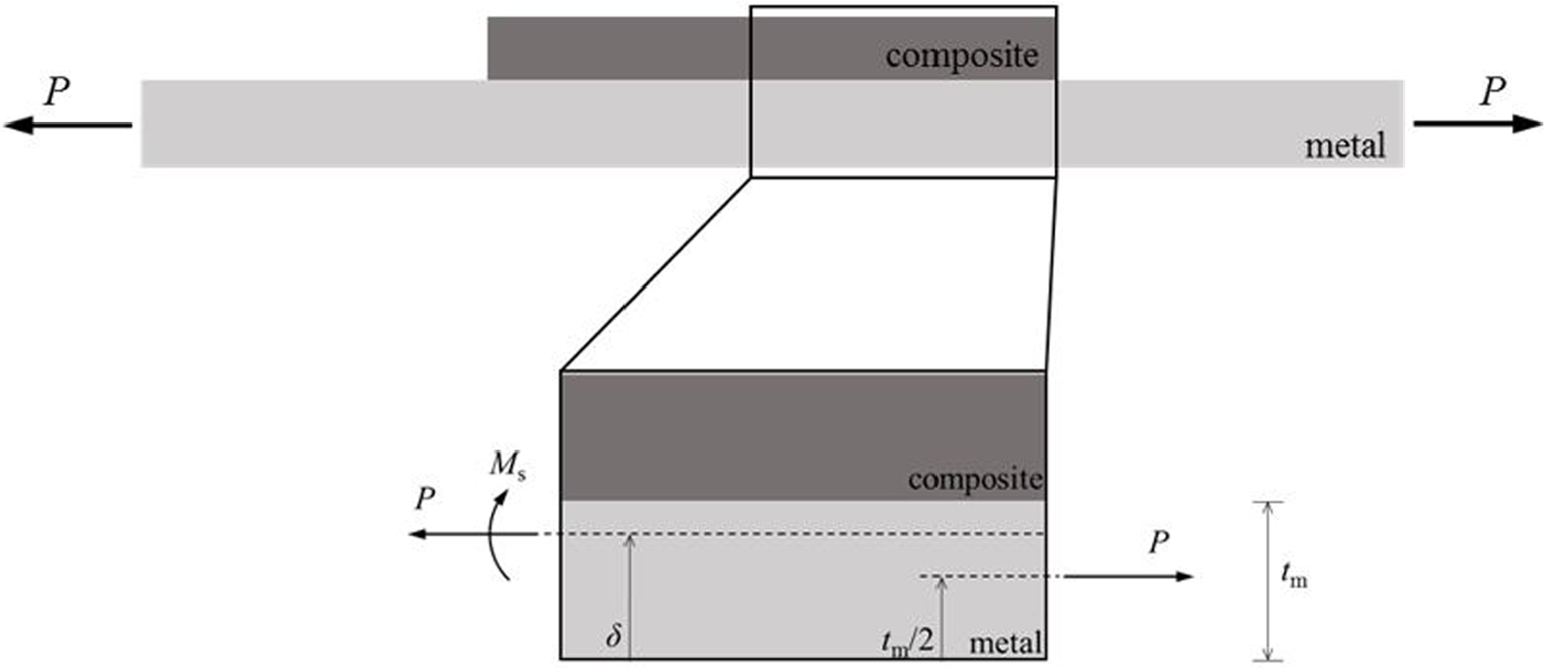
Secondary moment induced in an axially loaded unsymmetrical hybrid component.
This effect is well described by the constitutive equation (equation (1)), given in the mechanics of laminated composites. 29 Equation (1) is not being used directly in proposed work and is presented here only to demonstrate the mechanics of multi-materials and to stress out key design considerations
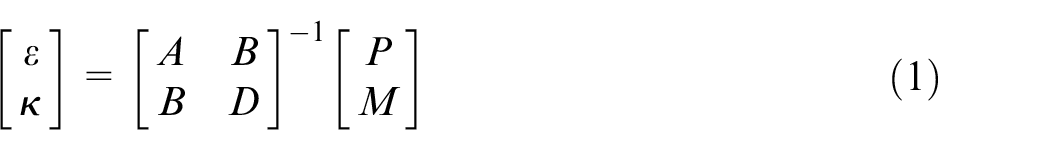
where ε is the axial strain of the reference plane, k is the curvature of the reference plane, A is the axial stiffness of the hybrid part and is a function of thicknesses and elastic constants, B is the coupling stiffness of the hybrid part and is a function of thicknesses and elastic constants and D is the bending stiffness of the hybrid part and is a function of thicknesses and elastic constants.
In the case of an unsymmetrical laminate (symmetry in material fiber orientation and thickness), which is the case shown in Figure 4, the coupling stiffness B is non-zero and leads to the development of secondary moment Ms in the multi-material. In the case of applying an axial force P to the hybrid part (M equals to zero and P is non-zero in equation (1)), the multi-material develops axial strain and due to the existence of the coupling stiffness B the material develops an in-plane bending curvature that result to bending stresses which in turn yield the secondary bending moment Ms.
This coupling effect opposes to the reinforcement’s concept of local stiffening with metal reduction and hence needs to be considered during the part design and dimensioning. One way to avoid the secondary loads induced due to coupling is to add a composite reinforcement of the same dimensions on the opposite side, thus leading to a symmetrically geometrical configuration. However, this might not be possible for some components because of the involved physical constraints such as manufacturability and accessibility. Alternatively, the designer could take advantage of the composite’s anisotropy and calculate the stacking sequence in an unsymmetrical hybrid system, which can yield a coupling matrix B of the composite itself that compensates for the geometric coupling effect.
Problem presentation
Problem formulation
A design approach is proposed intending to assist the engineer with the structural design process of a composite/metal bi-material part in an automated and efficient way. The problem of interest is schematically shown in Figure 5, where the metal of the reference (tm, r ) part has to be replaced by a composite/metal bi-material system. The selection of the associated geometric parameters should lead to a bi-material component that has the minimum possible weight, compared with the weight of the metallic reference part, while satisfying the imposed strength requirements for a given set of load cases. To achieve this goal efficiently, a scheme is used together with structural FE analyses. The associated design variables of the problem (composite/metal multi-material) are defined as follows:
tm: new reduced thickness of bi-material’s metal component;
n: number of layers of composite component;
[θ1, θ2,…, θn]: angle orientation of each layer in the composite component.
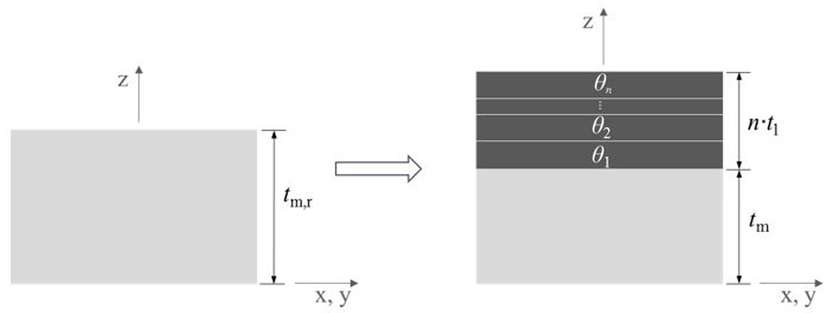
The problem of replacing a metallic material with a multi-material. The reference metal thickness tm, r is being reduced for weight savings and compensated with fiber-reinforced composite layers.
It is considered that all layers are manufactured from the same material and have equal thickness tl. The composite thickness is the product of the number of layers n and the composite layer thickness tl. Since tl is constant, then the total composite thickness is controlled by the number of layers n, which latter have been considered as a design variable. Additionally, each ply has a uniform fiber orientation over the selected area of the multi-layer application. It is apparent that the number of composite layers n controls the size of the vector containing the orientation of each ply.
In the design of composite materials, the design engineer has to calculate the orientation of each layer. From the engineering point of view, the fibers have to be parallel to the direction of the principal stresses, as these are calculated from an equivalent isotropic material. Mathematically, the layer orientations should minimize the strain energy developed in the composite material under the application of loads.19–22 This property can be used in the set-up of the problem by defining an objective function that minimizes the total elastic strain energy U as
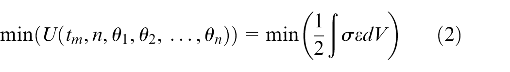
where σ and ε are the stress and strain tensors, respectively, and V is the total material volume. The magnitude of the stress and strain tensors depends on the applied loads, boundary conditions, the geometric parameters and the material properties. Here, focus is given on calculating the optimal design variables (tm, n, θ1, θ2,…, θn) and hence, the left-hand side of equation (2) shows U as a function of these magnitudes. In order for the effect of this objective function to be practically realized, the strain energy developed in an isotropic rod subjected to axial tension σ should be considered as
The thickness of the composite and the metal together with the density of the involved materials can be used to calculate the total mass. Since in this work no topology optimization is considered, then the mass is directly controlled by the number of layers n and the metal’s thickness tm of the multi-material. For this purpose, an additional objective function that minimizes the total mass M of the bi-material component is introduced as

The mass magnitude explicitly controls the weight of the hybrid part and hence, its minimization will lead to weight savings. However, the minimization of the total strain energy-objective function (equation (2)) ensures that the material will be optimally utilized, which is a prerequisite for achieving the minimum weight. Hence, the introduction of the min(SE) objective function is implicitly related to weight savings. In medium sized design spaces, an optimizer may yield the near “optimum” solution only using the mass minimization objective function. In large sized design spaces, the optimization may be trapped within local minima and not arrive to a global minimum. In the case of composites, where a number of plies are able to take many potential alternative combinations, the introduction of equation (2) narrows down the design space and assists with the arrival to a global minimum.
The problem might be subjected to several constraints, associated with design requirements, such as strength requirement, displacement requirement, stability requirement. Without any loss of generality, in this study, only a strength requirement has been considered, demanding that the stresses remain within the linear elastic region of the involved materials, has been taken. The von Mises yield criterion is used for the metallic layer as given by the following equation

where σeq is the equivalent stress calculated at a material point of the metal and defines a state variable. Sy is the material’s yield strength and is experimentally measured.
There are not yet any universally agreed failure criteria for composite materials due to their anisotropy and inhomogeneity.30,31 For this purpose, a failure index (FI) that applies to any of the available failure criteria for first ply failure calculation has been used herein. The FI-based criterion is evaluated at each material point of every involved composite layer and is defined by the following equation

where failure does not occur as long as FI remains below unity.
The generated design points (set of design variables) within the algorithm are guided by the two objective functions (equations (2) and (3)) and the two imposed design constraints (equations (4) and (5)).
Solver framework
Figure 6 illustrates the employed framework and the type of information exchanged between the FE and the solution modules. It refers to the mechanical design module presented in Figure 3. Following the literature analysis presented in the “Introduction” section, due to the nature of the problem, that is, multiple objective functions and discrete design variables, GAs were selected. In order for the proposed framework to be functional, the FE representation of the component should be parametrized with respect to the defined design variables (number of plies, ply orientation and metal thickness). The GAs followed the concepts of the biological evolution and they were conceived on the basis of Darwin’s theory of natural selection. 32 Therefore, it is common that the mechanisms associated with GAs be described through the use of terms, sourced from the language of microbiology, as their implementation mimics genetic operations. A GA works through genetic operations (crossover and mutation) and selection operations that aim at improving an initially selected random population. The selection operation usually involves a fitness function, characterizing the quality of an individual in terms of the objective function and the other elements of the actual populations. The GA is initialized through the definition of a randomly selected population (different design combinations) and at that point, iterations are performed in order to generate a sequence of populations from the initial one. At each step, genetic operations are applied to generate new individuals. The fitness of each available individual is computed and the entire population is ranked according to its increasing fitness. A subpopulation is then selected for the formation of a new population, based on the following process. Each discrete parameter is represented by a binary chain, corresponding to the number of levels. For example, a parameter with two values (levels) is encoded to one bit, a parameter with seven values is encoded to three bits and a n-bits chain will represent a parameter with 2(n – 1) values. The concatenation of these chains forms the chromosome, which will cross-over with another chromosome. In this study, the use of the one-point operator that randomly selects a cross-over point within a chromosome interchanges the two parent chromosomes at this point to produce two new offspring. 33
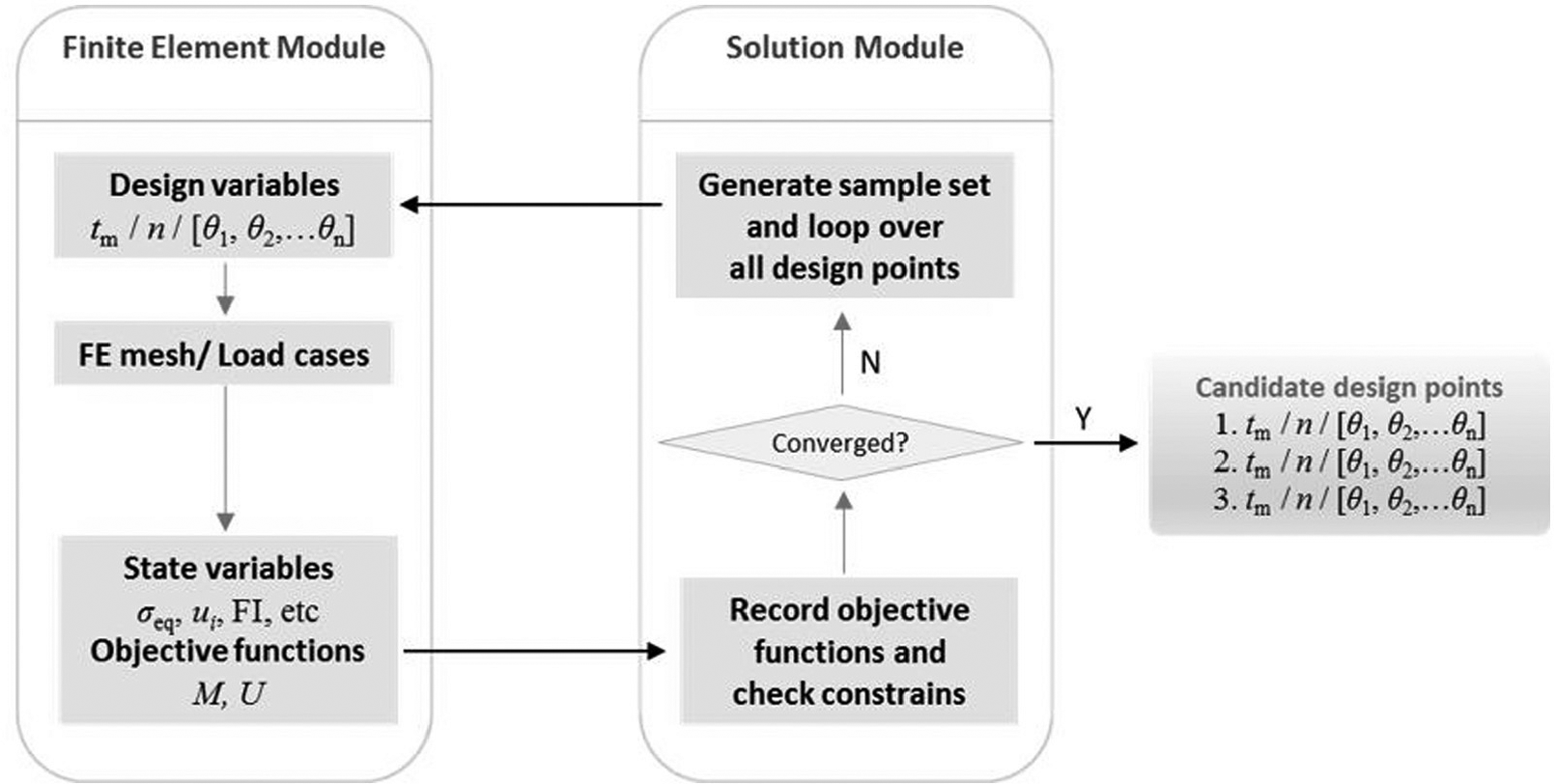
Proposed framework between the finite element and the solver module.
Each individual (design point) from the population (sample set), obtained through the solution module, based on GA operations, corresponds to a defined set of the design variables, used for the component’s updating of the FE mesh representation in the FE module. At this level, the load cases are assigned over the FE models together with the corresponding loading and boundary conditions and then the FE models are solved. Among the solution output parameters, the ones that define the state variables and the objective functions are further post-processed within the FE module and are next fed into the optimization module for evaluation. Once the convergence criteria such as maximum allowable Pareto percentage, convergence stability percentage, maximum number of iterations are met for the up-to-date sample sets, the algorithm yields candidate design points from the design space. Alternatively, the solver generates new sample sets of design points until the algorithm has converged.
Numerical implementation
The aforementioned framework was implemented in ANSYS Workbench v.17 commercial software, as shown in Figure 7. The FE models were constructed in Ansys Programming Design Language (APDL), which allows for full parametrization of the model input parameters, and customized post-processing capabilities. Within the Mechanical APDL module (template A in Figure 7), there is an assignment of the FE APDL code, where the input parameters are updated, based on the generated design points from the optimization module (template B in Figure 7). The APDL code includes (1) the geometry generation through points (known as keypoints in ANSYS), lines and surfaces, (2) the element type and material definitions, (3) meshing of the part, (4) application of load and boundary conditions, (5) solution submission and (6) post-processing.
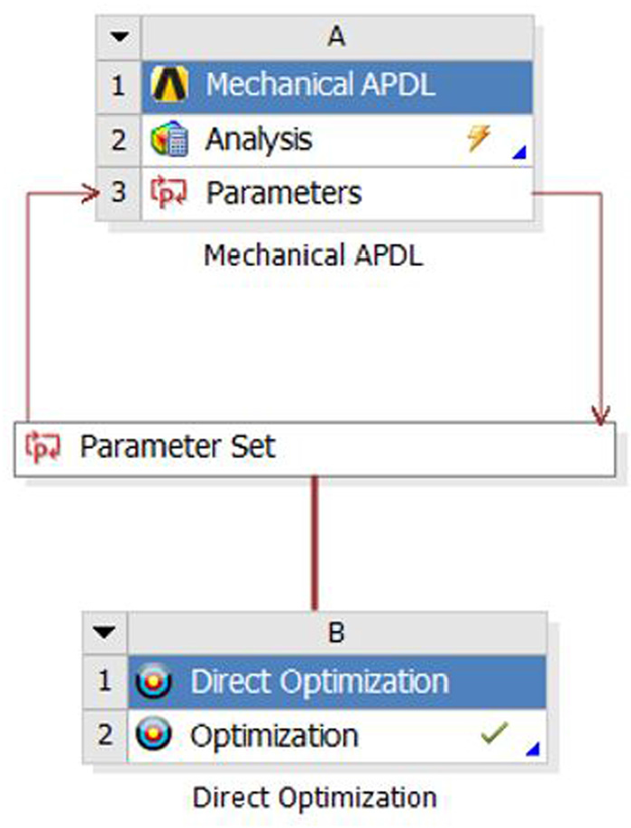
Implementation within ANSYS Workbench.
The FE mesh, loading and boundary conditions remain constant through the optimization. The variable magnitudes that evolve during the optimization are the design variables
The multi-objective genetic algorithm (MOGA) has been employed for the optimization, since it can manage multiple objective functions, together with discrete values of the design variables. 33 The MOGA is a hybrid variant of the popular non-dominated sorted genetic algorithm-II (NSGA-II) that can be used for both response surface optimization and direct optimization. It allows the generation of a new sample set or the use of an existing set for providing a more refined approach than the “Screening method,” defined in ANSYS. The screening method allows the generation of new sample set and sorts its samples based on objectives and constraints. It is a non-iterative approach and is available for all types of input parameters.
In this work, the MOGA algorithm which is robust in terms of optimization has been used instead of the “screening method.” In MOGA, an initial population that represents the first sample set of design points is generated. The objective functions/constraints are calculated for each design point. A new population is generated on the basis of crossover and mutation (GA principles) of the design points with the best fitness (in terms of objective functions and constrains) from the previously generated population. This process continues until the convergence criteria (maximum allowable Pareto percentage or the convergence stability percentage) or the stopping criteria (maximum number of iterations) have been met. The Pareto ranking scheme is done by a fast, non-dominated sorting method that is an order of magnitude faster than traditional Pareto ranking methods. 33 The “maximum allowable Pareto percentage” criterion looks for a percentage that represents a specified ratio of Pareto points per number of samples per iteration. Once this percentage has been reached, the optimization is converged. On the other hand, the “convergence stability percentage criterion” seeks population stability, based on the mean and standard deviation of the output parameters. When a population is stable with regard to the previous one, the optimization is converged. In detail, at the optimization initiation, the first population has not been taken into account because this population was not generated by the MOGA algorithm, since it was not used as a range reference for the output range (for scaling values). In this regard, the second population is used to setting the range reference. The minimum, maximum, range, mean and standard deviations are calculated for this population. Starting from the third population, the minimum and maximum output values are used in the next steps in order to scale the values (on a scale of 0–100). The mean variations and standard deviation variations are checked; if both of these are lower than the value of the convergence stability percentage property, the algorithm is converged. The constraint handling uses the same non-dominance principle as the objectives; thus, penalty functions and Lagrange multipliers are not needed. This also ensures that the feasible solutions are always ranked higher than the infeasible solutions. Table 1 lists the MOGA parameters that can be set by the user and their corresponding assigned values. These values result from the parametric analyses, the users’ experience and the recommendations provided in ANSYS. 33
Parameter assignment in the MOGA scheme.
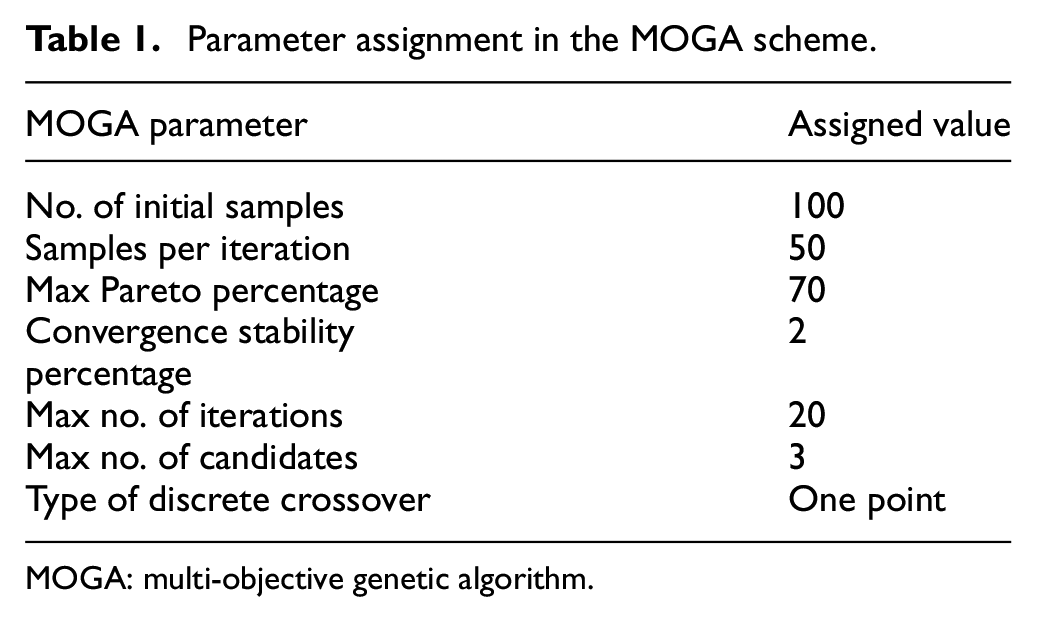
MOGA: multi-objective genetic algorithm.
A Python script has been created that allows for full parameterization of the optimization process, including the definition of the design variables discrete levels. Additionally, the optimization parameters of the MOGA algorithm were able to be controlled. These are the number of initial samples, the number of samples per iteration, the maximum allowable Pareto percentage, the convergence stability percentage, the maximum number of iterations, the maximum number of candidates and the type of discrete crossover.
Numerical examples
FE modeling and preliminary results
For the numerical verification of the developed scheme, three examples have been considered, as shown in Figures 8(a)–10(a). The overall aim, in all three examples, is the replacement of the metallic material with a composite/metal multi-material (see Figure 5) that weights the least possible and satisfies the strength requirement, by following the proposed multi-material design process for finding the set of parameters. It is important to note that the geometry of each example remains constant and only the cross-sectional parameters (design variables) are considered in the optimization scheme. In the first example, the plate is uniformly stressed in both in-plane directions (x and y) when subjected to uniform axial loads and bending moments, as shown in Figure 8(c). This example may represent a section of the skin of an aeronautical structure that is loaded under in-plane loads. The applied moments may result from boundary effects that come from the spar connections.
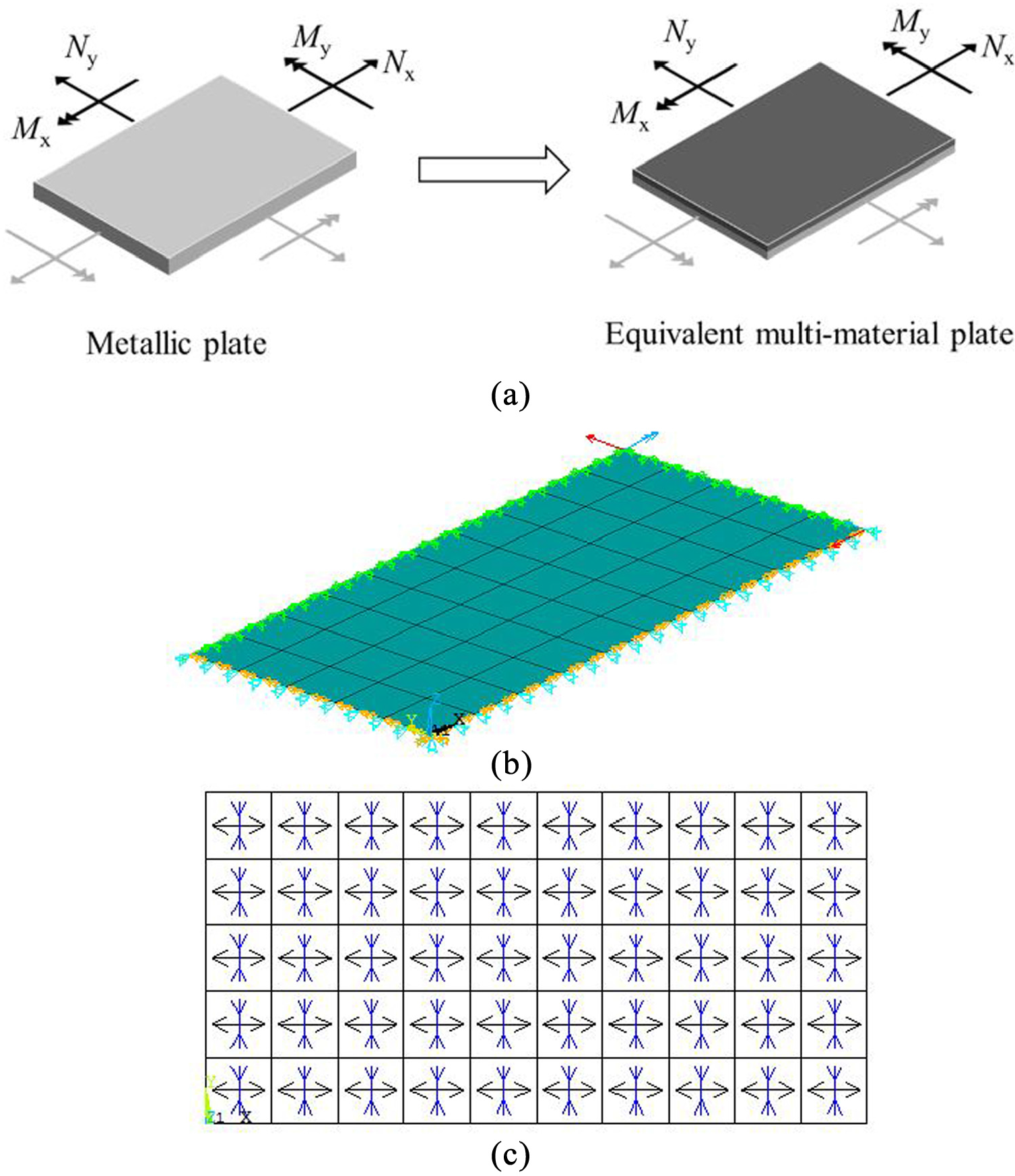
Example 1: Metallic plate subjected to uniform forces and moments and its multi-material equivalent (composite layers bonded to reduced thickness metallic plate) under examination (not to scale) (a), finite element model with loading and boundary conditions (b) and principal stress solution output of the metallic reference plate (c).
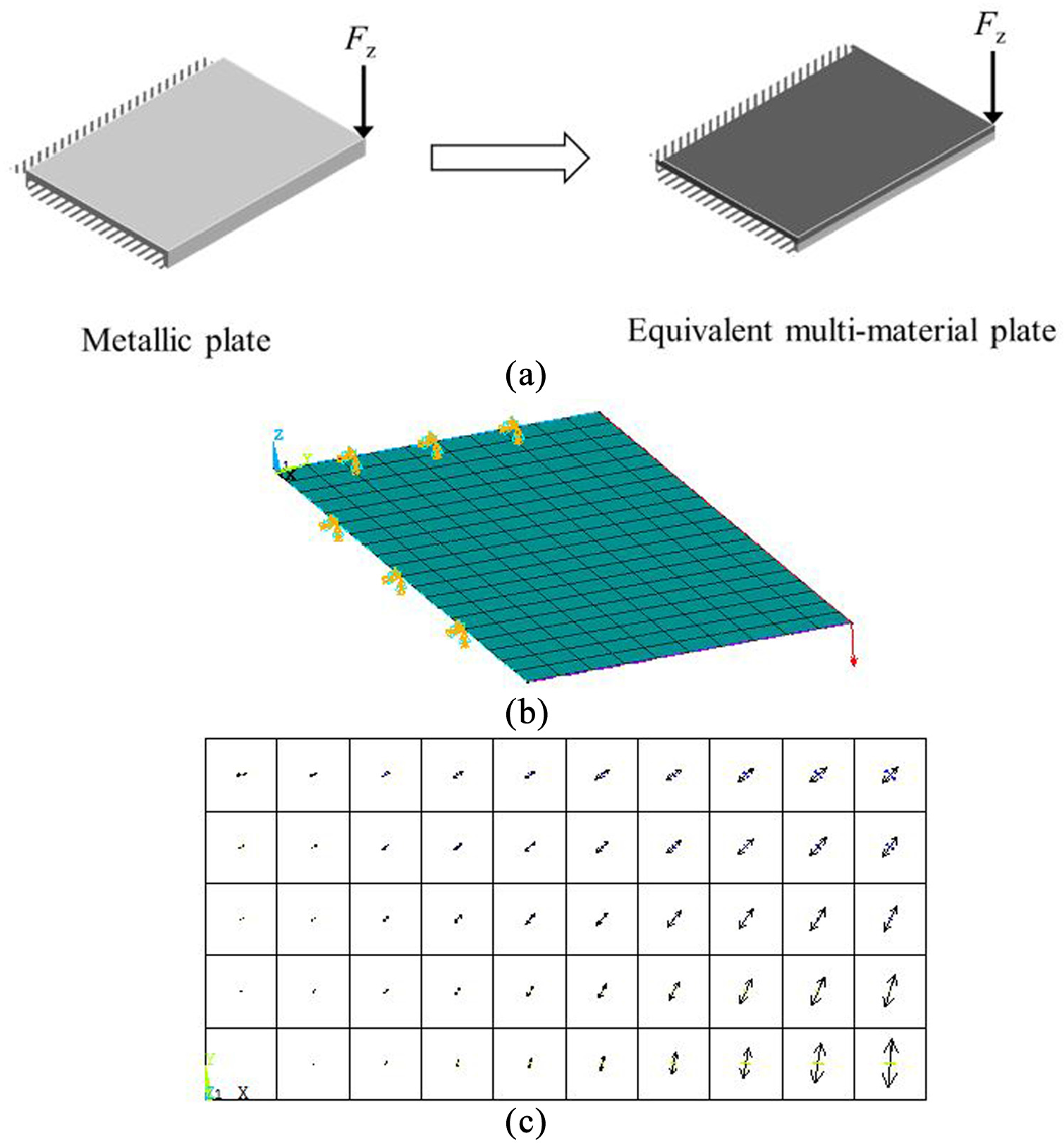
Example 2: Metallic plate subjected to a concentrated force at its free tip and its multi-material equivalent (composite layers bonded to reduced thickness metallic plate) under examination (not to scale) (a), finite element model with loading and boundary conditions (b) and principal stress solution output of the metallic reference plate (c).
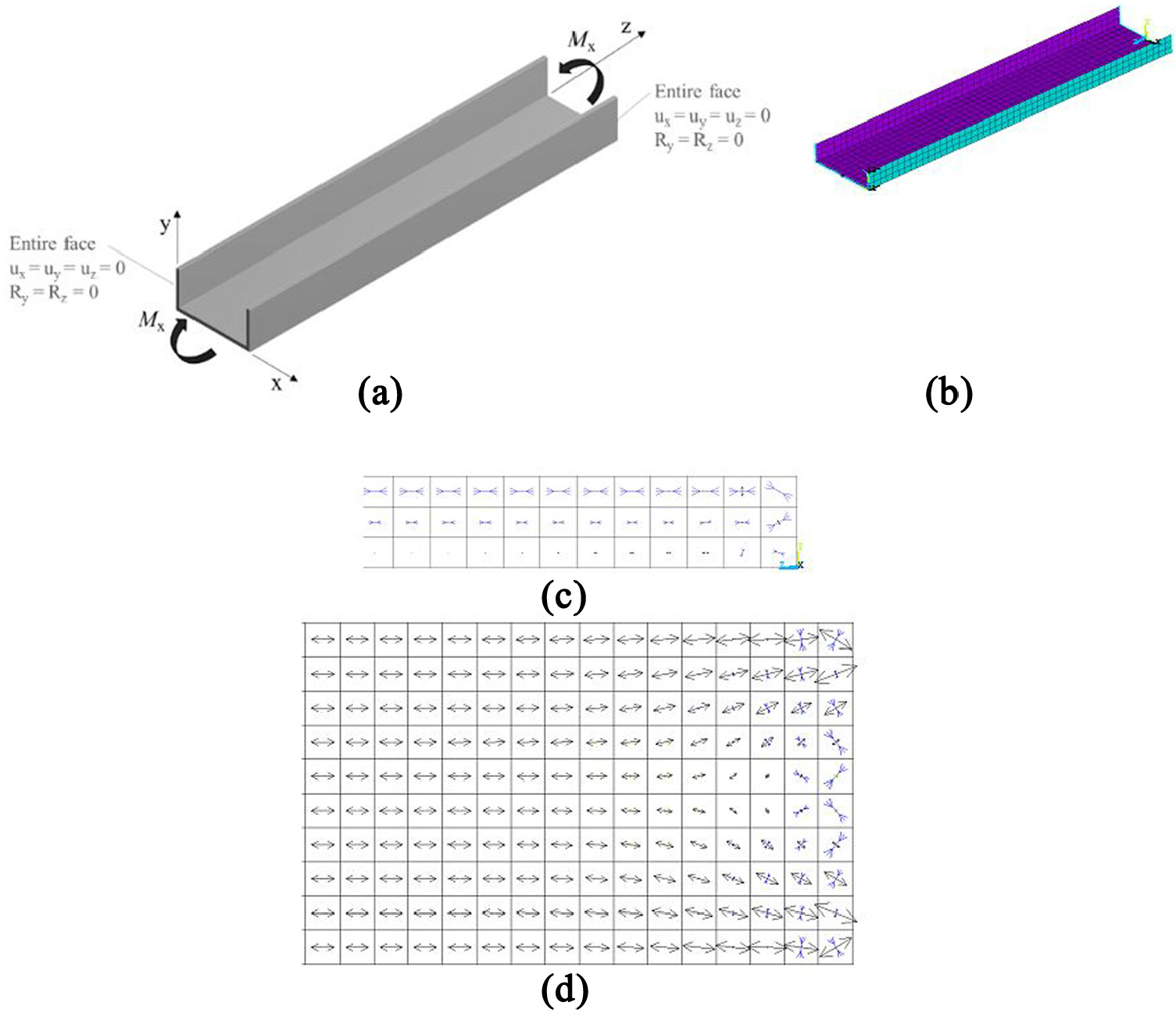
Example 3: U-channel structural beam subjected to uniform moment (a), finite element model with loading and boundary conditions (b) and principal stress solution output of the metallic reference U-channel at flange (c) and at the web (d), near the beam’s ends.
The second example involves a non-uniform stress distribution over the plate, when its free tip is deflected under the existence of a concentrated load, as shown in Figure 9(c). This case develops a complex stress state due to the variation of the bending moments along the length and along the width of the plate, which is the case of most structural elements.
The third example considers a structural beam with a U-shape cross section subjected to pure moment at its ends. This case represents the four-point bending test performed for simulating the crash worthiness of the B-pillar component (see Figure 1) in component test scale. The nature of this loading condition theoretically leads to the development of the uniform bending stress σy (with respect to the coordinate system shown in Figure 10(a)) along the length of the beam. However, the imposed boundary conditions (displacement and rotation constrains) disturb the stress field, near the ends and the bending stresses become uniform as one moves away from the ends, as shown in Figure 10(c) and (d). This effect introduces to the stress field a local complexity, which, in turn, is a challenge for the evaluation of the set of design variables in the proposed method. The three numerical examples considered in this work are selected for their simplicity in their geometry, loading and boundary conditions and the intuitive understanding of their response that is offered.
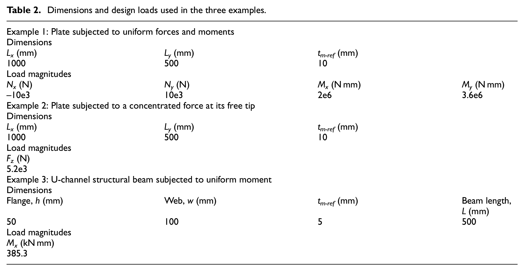
Initially, FE simulations of the three examples were performed by considering that the corresponding parts are fabricated only by metallic material, in order to evaluate an arbitrary set of loads/moments that when subjected to the plate, the metal reaches its yield strength (see metal properties in Table 3). The geometry considered and the resulting loading conditions for all cases are listed in Table 2. Given the relatively thin cross section of the adopted geometries, the FE discretization was based on eight-node shell elements (Shell 281 element available in the ANSYS element library). Figures 8(b)–10(b) present the FE mesh, together with the corresponding loading and boundary conditions. Modeling with shell elements is advantageous due to the design variables (
Dimensions and design loads used in the three examples.
Material properties for metal and composite. 34
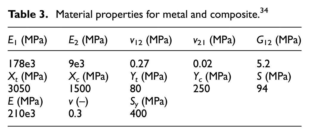
The properties listed in Table 3 is taken from the literature. 34 The failure criterion used for the metallic material is the one given by equation (4). In this study, a FI (magnitude below 1.0 denotes that the ply does not fail) which is the maximum value of the available failure criteria in ANSYS v.17 is used as calculated at all material points and all plies. 33
Numerical results and discussion
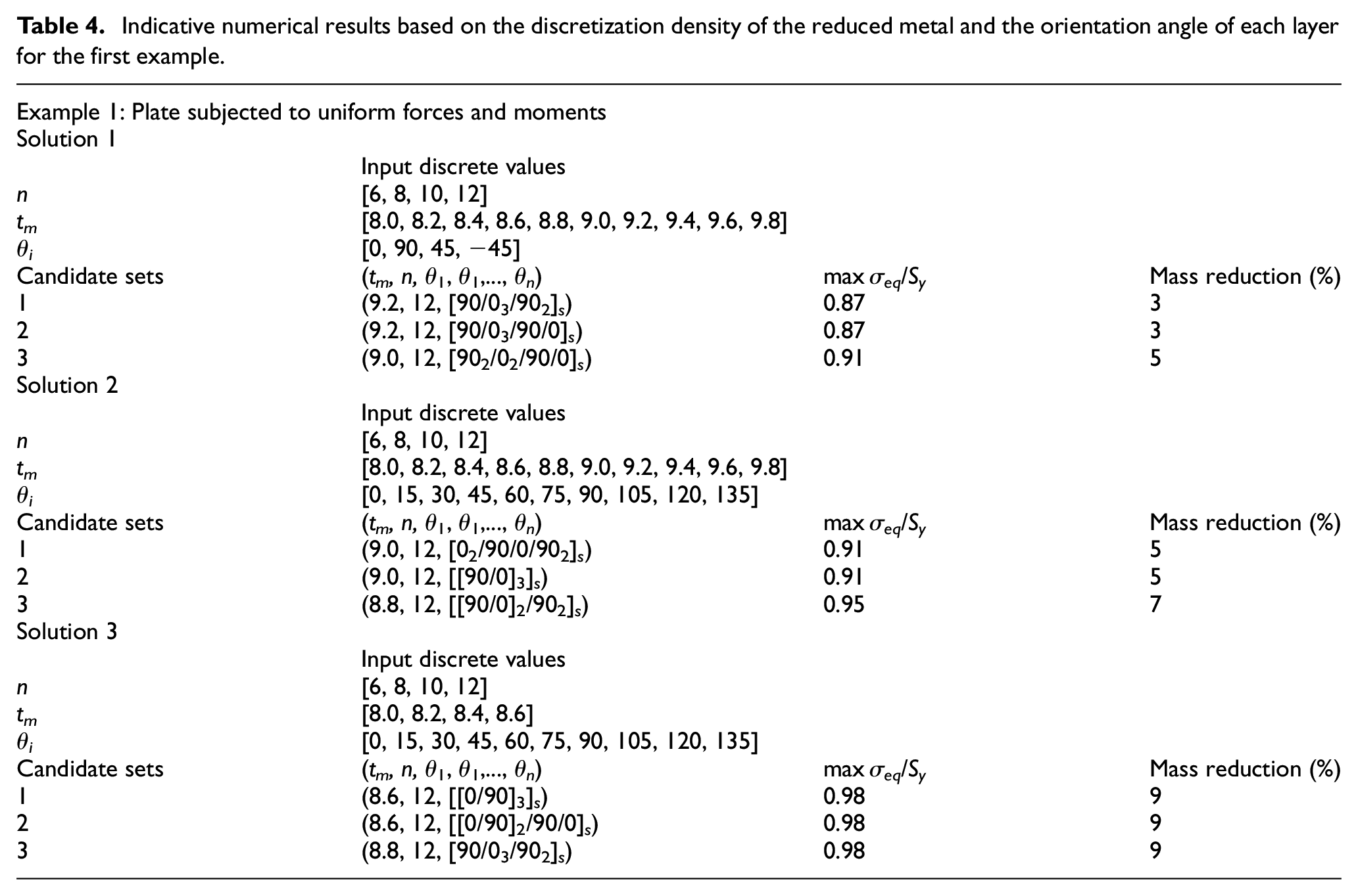
The number of design variables and the discrete levels per design variable (discretization density) control the size of the design space. The number of layers n controls the total number of the design variables, since n corresponds to the size of the angle orientation vector. In the case of a symmetrical stacking sequence, the size of the angle vector is reduced to the half in comparison to an unsymmetrical composite. The population numbers (number of initial and per iteration samples) set by the user in the MOGA scheme, together with the discretization density and number of design variables, are directly associated with the level of exploration of the design space. Parametric runs of the numerical scheme have shown that the discretization density has a significant influence on the resulted candidate sets (best set of design variables) and hence in the corresponding mass reduction. Indicative results are listed in Table 4 for the first example, that is, plate subjected to uniform forces and moments. To interpret the results, one has to correlate the maximum normalized equivalent stress (max σeq/Sy) with the metal thickness tm and the percentage mass reduction. It is evident that the level of metal utilization (max σeq/Sy = 1 corresponds to full utilization of the metal) controls the level of mass reduction, as seen in Figure 11(a) and (c). In other words, the best design that corresponds to the minimum weight of the bi-material component is constrained by the yield strength of the metal material. In all numerical solutions, the FI of the composite material remains at low levels (see Figure 11(c)) proving that the metal’s strength constraint guides the optimization algorithm to reach the minimum solution. Given the performed solutions, the best bi-material design could not exceed a mass reduction of 9%, as obtained from solution 3. The obtained stacking sequence from each solution is an outcome of the minimization of the strain energy that converged together with the mass minimization objective function, as shown in Figure 11(a) and (b). The candidate sets having resulted from all three solutions, include 12 composite layers, with stacking sequences comprising 0° and 90° orientations in different arrangements. This output qualitatively agrees with the principal stress directions, obtained from the solution of the reference metallic case (see Figure 8(c)). From the design point of view, the fiber orientation direction is the one being parallel to the direction of the principal stresses, calculated from a homogeneous and isotropic material.
Indicative numerical results based on the discretization density of the reduced metal and the orientation angle of each layer for the first example.
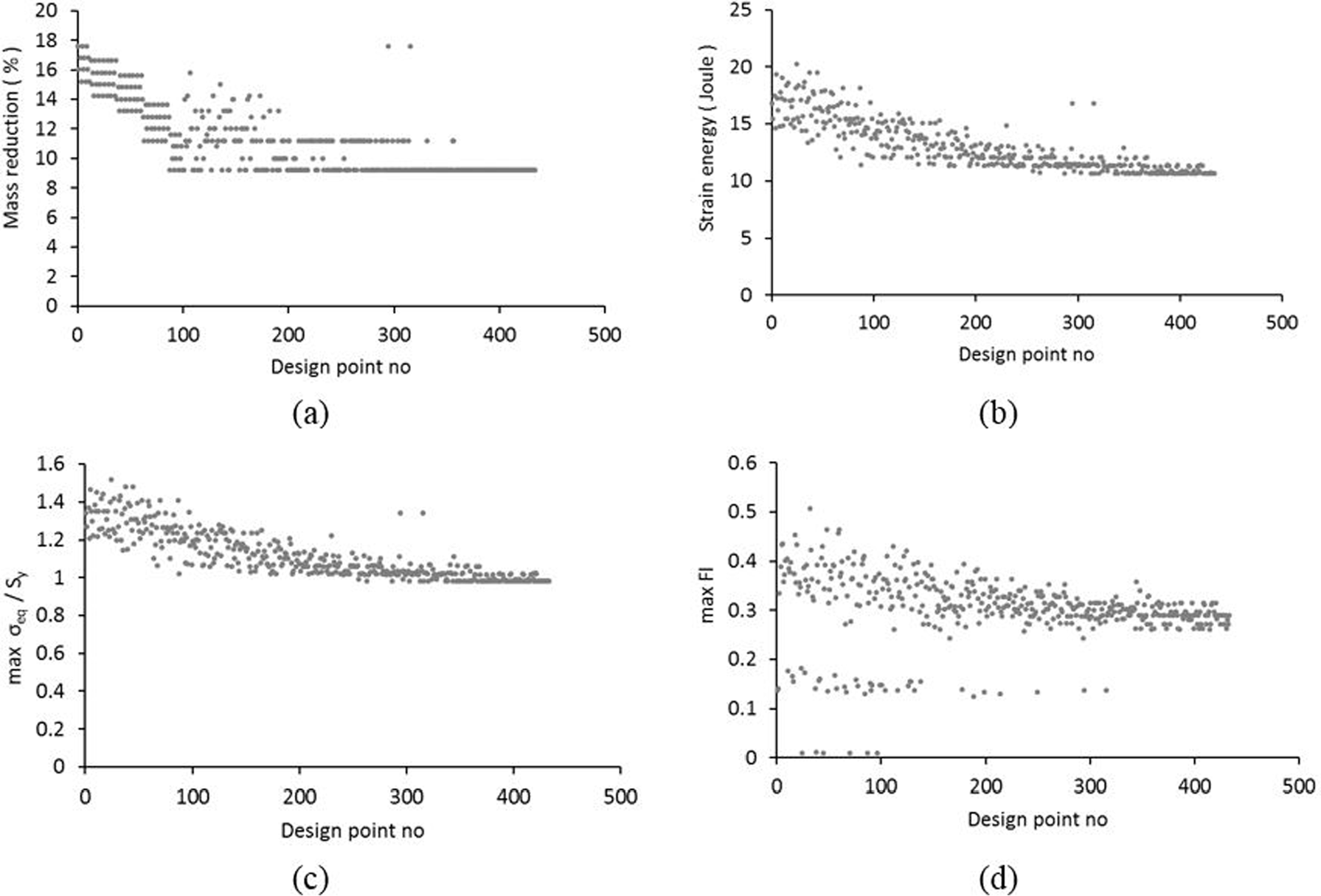
Evolution of the mass reduction (a), strain energy (b) objective functions, and max σeq/Sy (c), max FI (d) optimization constraints during the third solution for the first example.
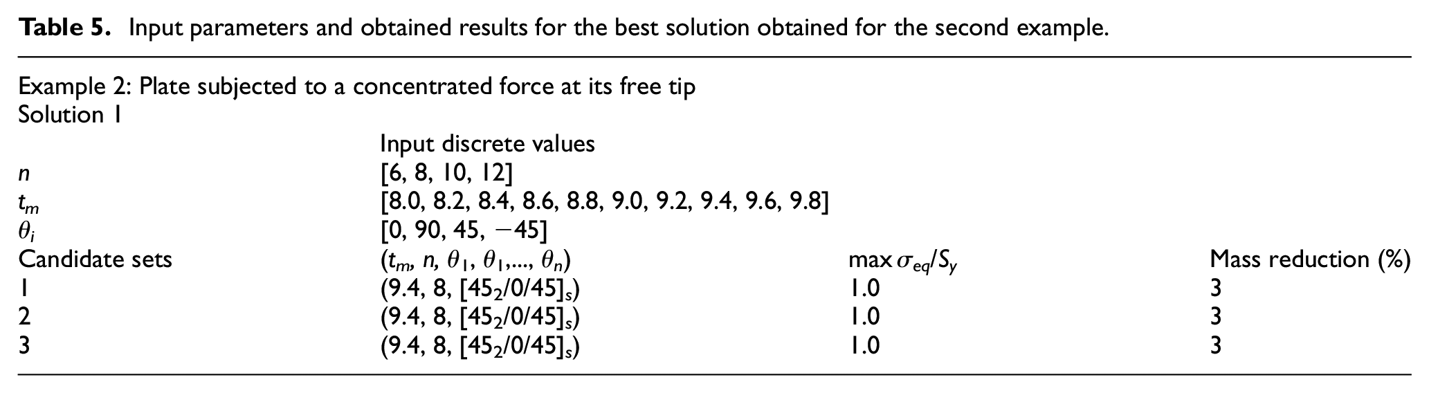
With regard to the second example, the best solution yields a bi-material part that has only 3% mass reduction, compared to the respective metallic reference part, as listed in Table 5. This outcome involves the full metal material utilization since max σeq/Sy equals to unity, no further mass reduction could be obtained. The coupling effect described in the “Key structural considerations of hybrid components” section significantly affects this outcome, since the best set of design variables involves eight layers of a composite part. Increasing the number of layers and decreasing the metal thickness does not lead to solutions that satisfy the imposed metal’s strength requirement. The stacking sequence of [452/0/45] s is aligned with the principal stress direction distribution, as shown in Figure 9(c).
Input parameters and obtained results for the best solution obtained for the second example.
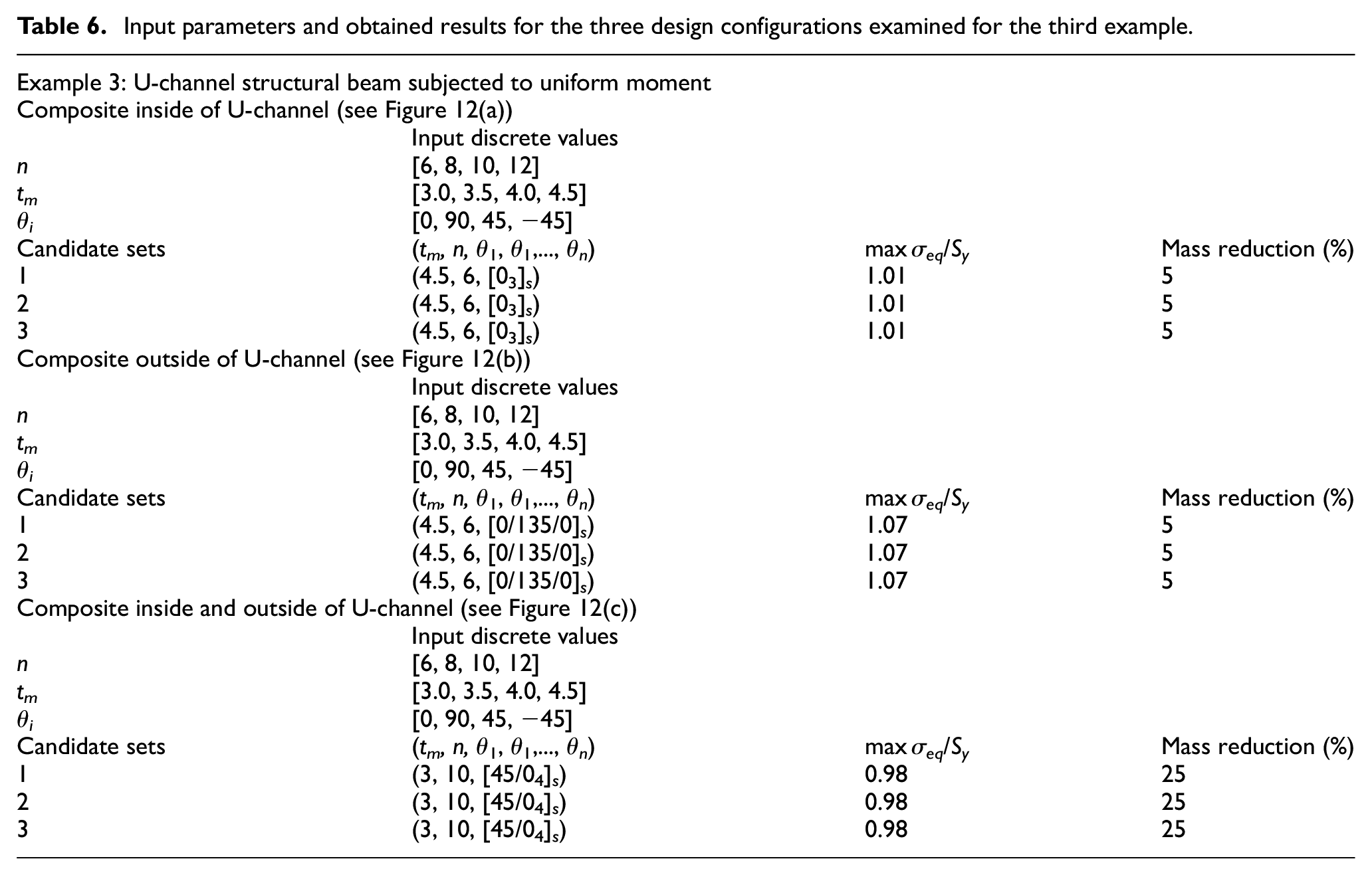
Three different design configurations have been examined in the third example (U-channel structural beam subjected to uniform moment), as shown in Figure 12. The U-channel cross section is symmetrical with respect to the vertical axis, passing from the middle of the web and it is unsymmetrical in the horizontal axis. Hence, the designer has the option of redesigning the part by placing the composite material inside, outside and inside–outside of the U-channel. From the structural design point of view, placing the composite material only at one side (inside or outside) introduces the coupling effect, discussed in the “Key structural considerations of hybrid components” section, whereas the coupling effect vanishes in the case that the composite is placed on both sides.Table 6 lists the corresponding best sets of design variables for the three design configurations. It must be noted that the max σeq has been calculated for the elements being away from the beam ends and represents the purely bending part of the beam (see Figure 13). This was done in order to exclude the spurious stresses developed at the beam ends and result from the multi-point constraints (see Figure 10). However, the entire FE mesh of the beam was used for the calculation of the model’s strain energy in order to examine the potentiality of the method to find the fiber orientations that govern the full beam.
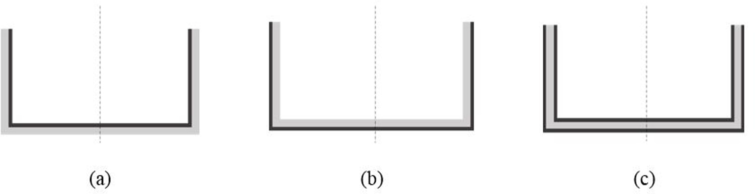
Different design configurations tested for the third example, composite inside of U-channel (a), composite outside of U-channel (b) and composite inside and outside of U-channel (c).
Input parameters and obtained results for the three design configurations examined for the third example.
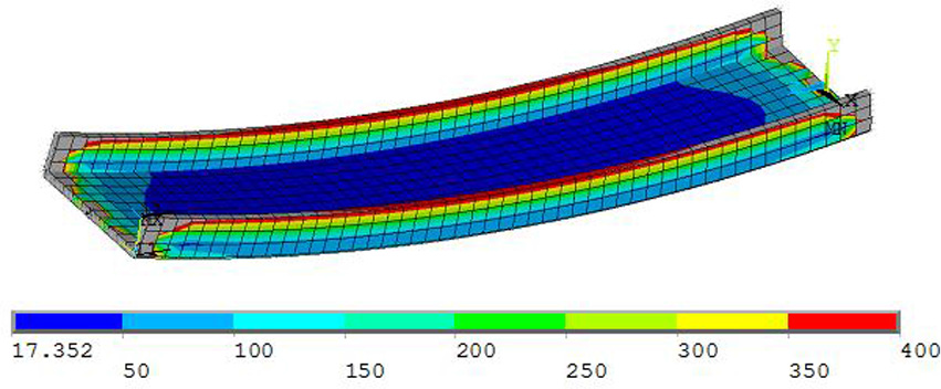
Equivalent stress σeq (MPa) distribution calculated for metallic reference case (the beam’s thickness shown is for visual purposes, since the model is constructed using shell elements).
For the single-sided design configurations (Figure 12(a) and (b)), the optimization scheme did not converge to a set and hence the candidate sets given in Table 6 should be regarded as “good” solutions. Single side placement of the composite material results in the development of high stresses in the metal component of the bi-material part. This effect subsequently sets a constraint on the level of mass reduction, which is equal to 5% with the use of 10% thinner metal, compared to the reference thickness. The resulted number of layers is equal to 6, denoting that a further increase in the composite thickness and a subsequent decrease in the metal thickness, for additional weight savings, cannot be achieved, as the coupling effect gets magnified. On the other hand, double-sided composite placement in the U-channel (Figure 12(c)) yields promising results with respect to mass savings, reaching the level of 25% (see Table 6). This is achieved with a 40% reduction in metal thickness and the use of 10 composite layers on each side of the U-channel cross section.
Conclusion
A structural design approach for multi-material components is presented in this study. The scheme is implemented in ANSYS for the design of three composite/metal bi-material examples. Based on the adopted procedure, the following major conclusions are derived:
The minimization of the component’s strain energy, acting as one of the objective functions for the solution algorithm, efficiently leads to the stacking sequence of the composite material.
The discretization density namely the number of discrete levels per design variable which affects the size of the design space should be carefully set.
The level of mass reduction is constrained by the metal’s strength requirement and consequently its corresponding thickness. This conclusion is valid for the cases where strength consideration is the key design issue.
The composite layers when aligned (i.e. minimum strain energy) are characterized by a 30% or less material utilization (FI < 0.3), denoting that the metal is limiting any further mass reduction.
Footnotes
Acknowledgements
This work is under the framework of EU Project Communion.
Declaration of conflicting interests
The author(s) declared no potential conflicts of interest with respect to the research, authorship and/or publication of this article.
Funding
The author(s) disclosed receipt of the following financial support for the research, authorship, and/or publication of this article: This project has received funding from the European Union’s Horizon 2020 research and innovation programme under Grant No. 680567.