
Abstract
Active flow control devices have been proven to reduce drag and delay stall on commercial aircraft. This leads to lower fuel usage and thus reduced flight costs. However, there is a large uncertainty as to how to integrate active flow control devices into aircraft, specifically those with composite structures. In addition, the cost of manufacturing active flow control devices for large-scale production has not been previously studied. In this article, design concepts for the attachment of a fluidic oscillator to a composite aircraft structure are investigated. A systematic approach from the conceptual design to the final design is performed using different design tools. A cost analysis is performed to select the most cost-effective design configuration based on large volume fluidic oscillator production. Through design validation and cost estimation, the final design is shown to be feasible for large volume manufacturing.
Keywords
Introduction
During aircraft flight, it is necessary to reduce drag and delay stall over the wing surface. Stall on wings occurs when the critical angle of attack has been reached; when this occurs, less lift is generated due to decreased attached flow. Flaps are used to increase the overall camber of the entire wing to prevent flow separation at higher angles of attack. While flaps lower the overall flow separation across the entire wing, there is still local flow separation that occurs at the flap wing surface. This can be reduced using active flow control (AFC) devices to create vortices that invigorate the boundary layer and prevent separation. There are numerous methods for creating an AFC device, including using an actuated air inlet flow to create an oscillating jet or using a piezoelectric actuator to drive the oscillating jet. This article focuses on an AFC device using fluidic oscillation, as shown in Figure 1. 1
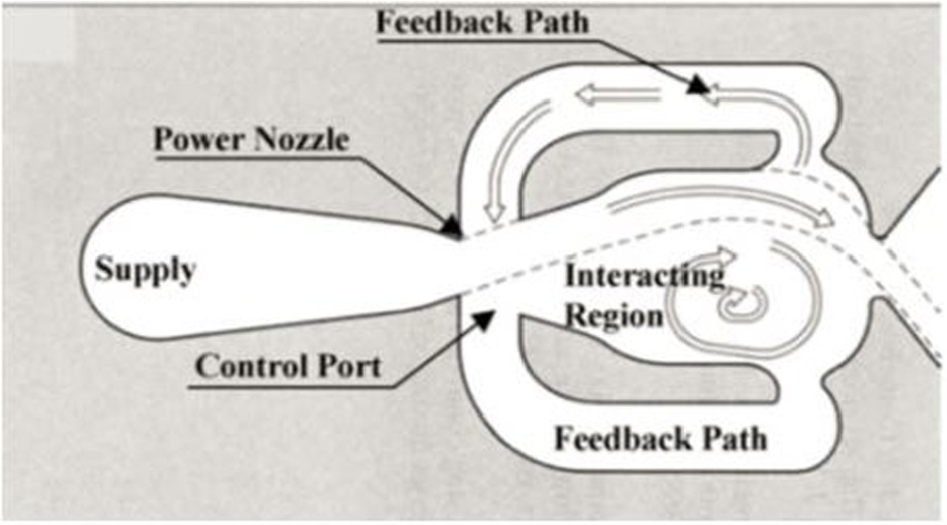
Fluidic oscillator.
AFC devices that use oscillating jets have been developed since the 1960s. Aerospace companies such as Airbus and Boeing have researched the incorporation of fluidic oscillators (FOs) into wings and wing flaps to prevent flow separation.1,2 In these studies, FOs were fastened to metal components with slots cut out of the thin aluminum skin to expose the jets to the free stream. While successful, all of these tests were conducted on airfoils constructed of metal components, rather than composite materials, which pose integration issues.
An issue with attachment to a composite skin is the structural damage caused during the creation of holes. Holes create local stress concentrations, in addition to delamination and fiber breakage. 3 In order to reduce the number of holes created, other attachment alternatives are considered. Adhesives are commonly used in composites due to their nondestructive nature, resistance to vibrational stress, and ability to distribute a load over a wide region. Snapfits are also widely used with polymer materials due to their speed of attachment and lower part count. In the design described in this article, an adhesive is used to attach the FO to the skin, while a snapfit is used to attach FO components together.
Through a joint project with Boeing, research at the Georgia Institute of Technology showed the implementation of rows of FO devices into a composite wing flap. 4 This research focused on the integration of the FOs by embedding the devices into the composite skin. Several alternative configurations were studied including the insertion of the devices from the top or the side and embedding them into the composite skin, or by installing them from on top into a wing groove and applying an adhesive for attachment. While these configurations provided feasible solutions for integrating the devices into the skin, they did not allow for serviceability as the attachment methods were permanent. A recent paper by Li and Colton 5 showed the attachment design of a FO into a composite wing-flap front bullnose. However, this design focused on attaching the FO to a non-structural, fiberglass part of a wing flap, where it will be more accessible for servicing rather than a structural region within a wing flap. Research at TU Dresden in Germany integrated an AFC system into a carbon fiber (CF)-reinforced wing flap. 6 An additional spar was placed inside the flap and screwed into place and the FO was attached to the underside of this spar. Although polymer material was considered, the spar was made out of aluminum as the polymer was deemed too flexible and would lead to issues with torsion and bending. 6 In addition, the FO parts were constructed from aluminum.
Prior FO research does not consider design manufacturability, specifically with respect to large production volume, which is important for commercial aviation applications. Due to the complex geometry inside a FO and its hollow chambers, FOs are generally manufactured in multiple parts. Three-dimensional (3D) printing has facilitated enhanced manufacturing by successfully creating complex geometries in a single part. Prior research has used 3D printing techniques to create the FO’s small and complex geometries and to reduce overall part count.4,5 Manufacturing methods for micro-FOs, which are similar to FOs, have also been studied. Research by Becker provided an overview of several methods including 3D printing, injection molding (IM), precision machining, and thermoforming, while research by Glenn provided estimates for FO manufacturing costs using different manufacturing methods at several batch quantities.7,8 Thermoforming was once again found to be effective for small quantities, while IM and compression molding were effective for high part volumes in excess of 10,000 parts. Li and Colton 5 also conducted a cost analysis for three FO designs for a non-structural wing region. 3D printing was found to be useful for small part counts, while IM was more cost effective for part counts larger than 1000 parts.
This article presents an FO fabricated from composite materials that is suitable for high volume production and can be integrated into a composite aerodynamic structure. A CF-reinforced thermoplastic polymer is used to manufacture the FOs; therefore, IM and selective laser sintering (SLS) processes are considered for production. Functional requirements (FRs) and design parameters (DPs) are first created with axiomatic design (AD) methodology. Design concepts are then generated and compared to create a final model. Finally, a cost model is used to study the FO costs based on different manufacturing configurations, and recommendations are presented. Further details are documented by Aly. 9
Design generation
The first step in generating designs for the FO attachment was to identify the customer attributes (CA) and FRs. AD was used in the first phase of the design process to eliminate unsatisfactorily coupled designs. 10 Morphological charts were used to generate feasible design solutions. Sketches were made of these designs, followed by 3D models. Costs were estimated for each of the designs, which were ranked based on their cost. Sensitivity analysis and design of experiments were conducted to evaluate the design rankings based on cost parameters.
AD
AD was used as a systematic approach to generate design concepts while reducing complexity and eliminating coupled designs. 10 Coupled designs have non-independent FRs, where altering one FR necessitates changing another FR.
The first step in the AD process was to generate the CA in the customer domain. The main customer needs were to create a working FO and to integrate that FO into a composite wing flap. These customer needs were synthesized into the three main CAs and FRs. DPs required a crossover to the physical domain to create a DP for each FR. First, high-level DPs were created for each corresponding FR. After that, a zig-zag approach was utilized to shift back to the functional domain and breakdown the top-level FR into sublevels. For each FR sublevel, a corresponding DP sublevel was generated. This process was carried out until all of the FRs were satisfied and would no longer need decomposition. The decomposed hierarchies for the FRs and DPs are shown in Table 1. From the decomposed hierarchy, the design process was divided into three main FRs:
Manufacturing the actuator to produce an oscillating flow control device;
Attaching the actuator to the flap structure;
Connecting the actuator to the flap skin.
Functional parameters and design parameters decomposition.
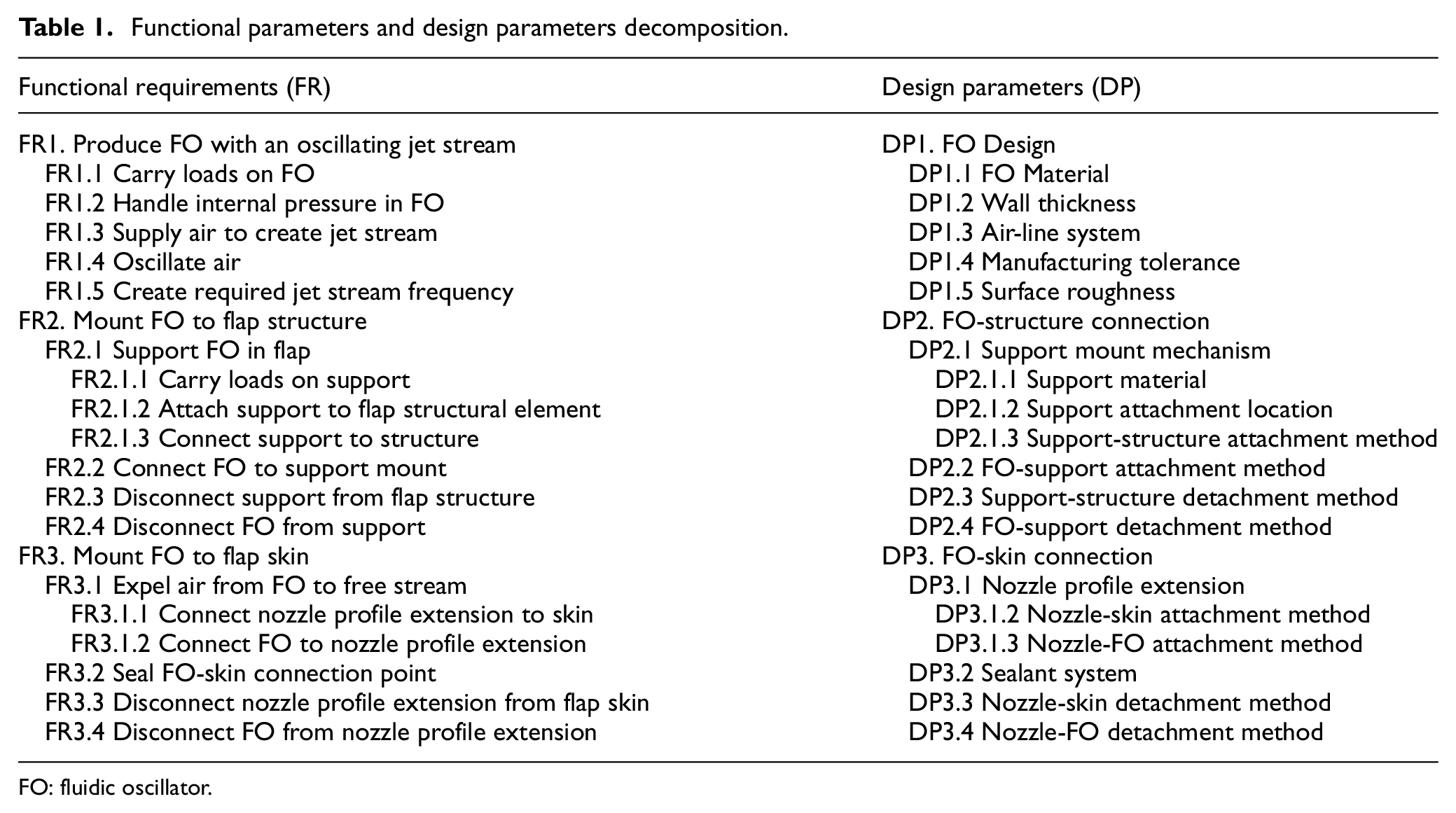
FO: fluidic oscillator.
Constraints were created to ensure that DPs do not violate any specified limitations. Constraints were placed on the actuator device and on the actuator integration, as summarized in Table 2. Constraints on the device included temperature and pressure loadings, actuator sizing, and air supply ducting. Constraints for the integration involved the angle of the device with respect to the flap skin surface, actuator spacing along the flap span, and flap loadings.
Design constraints.
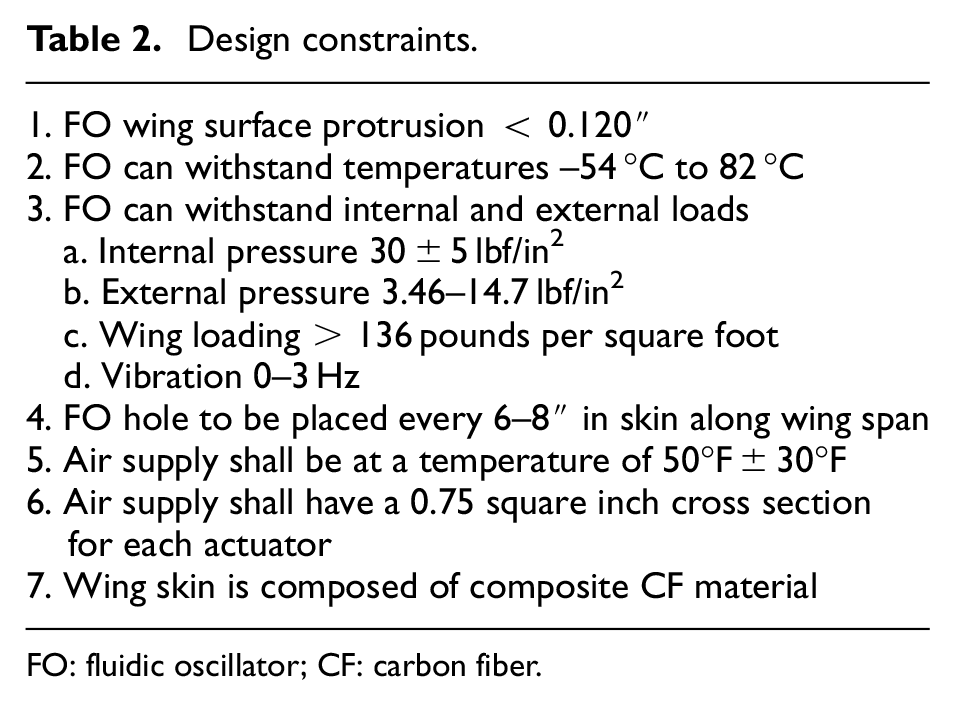
FO: fluidic oscillator; CF: carbon fiber.
Concept generation
AD laid the framework for determining solutions through the Independence Axiom. Doing so allowed for the creation of design solutions for each DP that were not coupled to each other. For each DP, viable solutions were listed to accomplish the desired function. Solutions were also required to fit the system constraints, such as allowing for servicing, manufacturing, and low cost.
Once the solutions for each DP were selected, morphological charts were used to create design solutions. One or more solutions was chosen for each parameter, and the combination of the different solutions for the parameters constituted a design solution. This can be seen in Table 3 with the highlighted cells representing the solutions that were chosen. This was systematically carried through to generate multiple uncoupled designs.
Morphological chart selection
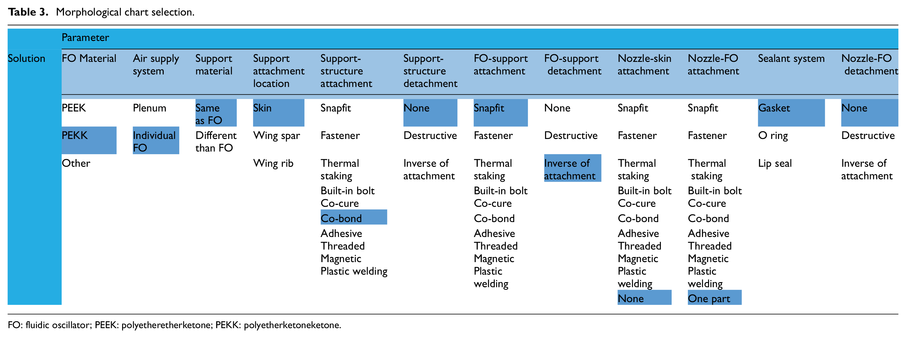
FO: fluidic oscillator; PEEK: polyetheretherketone; PEKK: polyetherketoneketone.
Design comparison
Numerous design configurations were created through the morphological charts and were then evaluated by comparing their estimated product costs. 9 The product cost consisted of the material and assembly costs. The material cost was the product of the material cost per weight and the weight of the design, while the assembly cost consisted of the product of the labor rate of $18 per hour and assembly time. 11 The product weight was also tabulated for each design to provide another measure of comparison between cost-efficient designs. An example listing of the internal designs with their calculated costs and weights is shown in Table 4, with rankings listed for each design based on the lowest estimated total cost. The total cost and final rankings are shown in bold. Internal designs included FOs that were inserted from inside of the flap, while external designs were inserted without internal flap access; internal-external designs utilized a combination of both.
Design costs for internal designs.
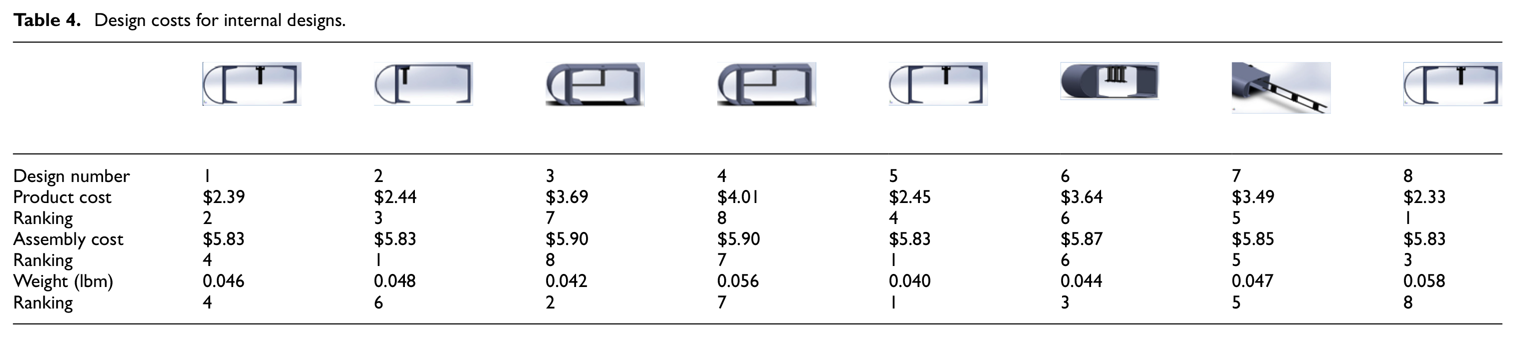


With regard to the design rankings, a vital question was whether the rankings would change if certain parameters affecting the product cost were changed. The most notable parameters that affected the product cost were material cost, assembly time, material density, and flap skin thickness. Skin thickness affected the cost as greater thicknesses required more material to fill the hole and support the FO. Although varying the material density does not make physical sense as it is a material property, it was varied to understand how the model would change with respect to this key parameter. A sensitivity analysis was conducted to determine how the relative rankings of the designs changed relative to a change in a key parameter in the cost equations. Each of these parameters was varied by a high factor (2) and low factor (1/2) to view the spread of the data. As each of these factors was varied by the high or low factor, the resulting cost of each design was updated to reflect this parameter change. These new costs were compared to understand how changes in key parameters affected the product cost.
The results from the sensitivity analysis are shown in Figure 2. Each bar represents a different design, with the center dots representing the original design’s predicted cost, before varying the parameter. Error bars are attached to each design to show the variation in cost when the parameter was varied by the high and low factors. The designs are shape coded with internal designs as circles, external in triangles, and internal-external in squares. When each factor was varied, assembly time showed the largest change in cost, followed by material cost and material density. In all of the parameter variations, however, the rankings did not significantly change between individual designs; the low-cost designs remained the low-cost designs while the higher cost designs were still more costly. This showed that design rankings were not affected by changes in the cost parameters.
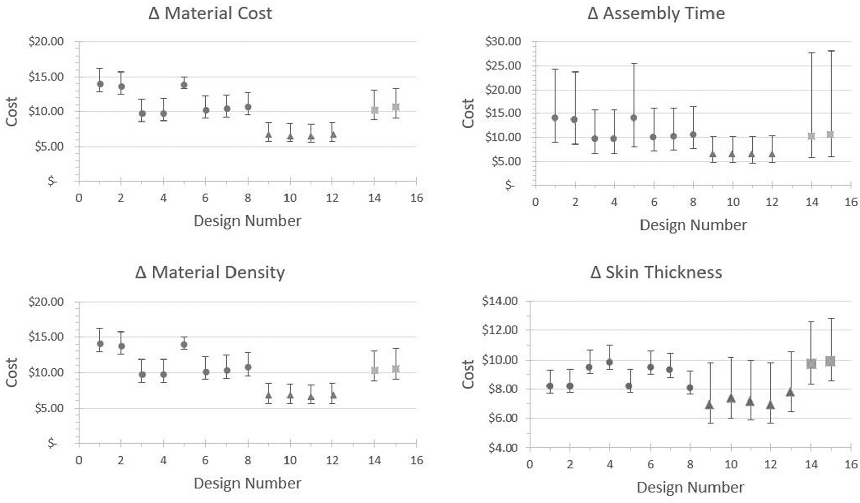
Sensitivity analysis.
FO design
The results from the sensitivity plots showed that, despite changes to the main cost parameters, the overall rankings between designs did not vary. Knowing this information, the top design, that with the lowest cost, was selected and refined to create the final design. The FO design can be seen attached to the flap in Figure 3. The design consists of three parts: the actuator, actuator cover, and the sleeve.
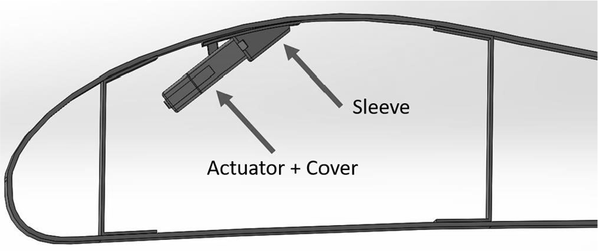
Final design attachment.
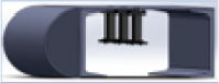
The actuator shown in Figure 4 mixes intake air inside of the internal chamber before expelling it into the free-stream. Rounded edges are used instead of sharp corners along the outside part surface to reduce stress concentration regions and aid in manufacturing. A uniform wall thickness is used in the actuator to allow for uniform cooling throughout the part, which is important for IM. The exit side of the actuator has a recessed groove that allows for an O-ring to be inserted to provide sealing.
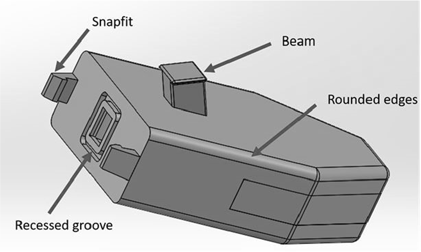
Fluidic oscillator actuator.
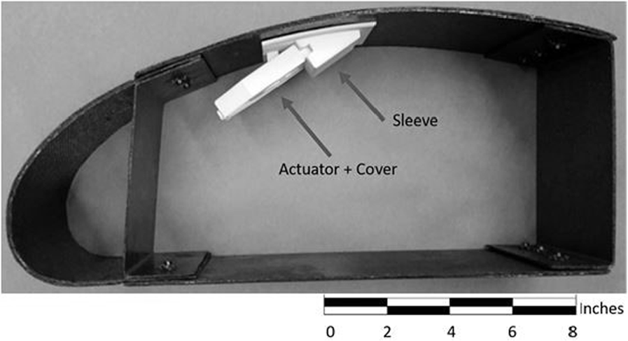
The actuator is closed off by adding a cover to the top of the FO design. Depending on the manufacturing process, the actuator cover can be produced as a separate part (IM) that is mechanically attached or is manufactured as one part (3D printing). The cover and the actuator, shown as two separately manufactured parts, can be seen in Figure 5. If the cover is manufactured as a separate part, a high temperature polymer adhesive can be used to attach and seal the two parts. Ultrasonic welding may also be used, but due to the high CF filler content within the polyetherketoneketone (PEKK) material, a heat-treated steel or carbide-faced titanium horn would have to be used. 12
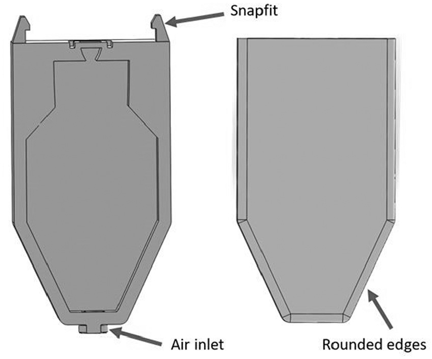
Fluidic oscillator actuator (left) and actuator cover (right).
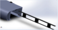
The last FO component is the sleeve attachment shown in Figure 6. This part is an intermediate connection point between the actuator and the wing skin surface. The sleeve is attached to the bottom surface of the skin with the protruding nozzle extending through a surface hole. The sleeve contains a large outer lip area that allows for more contact area between the sleeve and the bottom skin surface. This provides an adequate bonding area needed to keep the sleeve in place and to prevent peeling off from the wing. The actuator attaches to the bottom surface of the sleeve with snapfits that hold the device in place and ensure proper compression on the sealant surface to prevent air leakage.
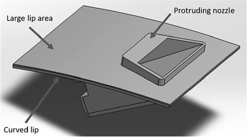
Fluidic oscillator sleeve.
Throughout the design generation, design for manufacturing and assembly (DFMA) was utilized to simplify the design of the parts, reduce the number of parts, and to reduce the overall time and cost associated with the manufacturing and assembly of the device. 13 Examples of this include the integration of the nozzle which expels the air into the sleeve design to limit the part count and lower the assembly cost. Snapfits were used to connect the actuator to the sleeve due to their limited use of tools required and quick assembly and disassembly times. The usage of the beam at the top surface of the actuator helps with the normal loading on the device but also helps with part orientation during assembly that reduces the handling time.
The FO material selected was CF-reinforced PEKK due to its high strength, high glass transition temperature (Tg), toughness, and ability to be injection molded. 14 PEKK material has a high toughness which is important for damage tolerance which has become more significant in aircraft vehicle design. 14 In addition, PEKK has good ultraviolet (UV) resistance, which is essential to parts exposed to sunlight on airplane structures, as well as to aerospace chemicals, fuel, and solvents. CF was used as the reinforcement due to its high strength to weight ratio and high tensile modulus to weight ratio. CF also has excellent fatigue resistance, which is essential to sustain the parts under repeated flight loads for the duration of several hundred flights before replacement. 3 In addition, CF was used due to its compatibility with the existing thermoset CF material of the flap skin and structure. This is important so that thermal expansion properties are closely related between the interfacing materials.
After generating the computer-aided design (CAD) model, a physical model was fabricated to create a visual mockup of the design. This model was made to the full-scale dimensions of a generic flap wing with a 15 cm span, identical to the CAD model. The final design, represented as a physical mockup, is shown in Figure 7 with a CF flap skin and fused deposition modeling (FDM)-printed actuator parts.
Fluidic oscillator physical model.
Cost analysis
A cost analysis was performed with respect to mass production. The cost was divided into manufacturing cost, material cost, and assembly cost. Calculations for the material and assembly costs were similar between different processes, but the manufacturing cost calculation differed for IM and SLS 3D printing. IM is suitable for high production volumes, as it has a very short cycle time as compared to machining. 14 3D printing can create complex geometric without the assembly of multiple parts and can create different part geometry modifications without requiring a new mold. Stereolithography printing (SLA) is limited to thermoset materials, and FDM has a higher surface roughness when compared to SLS; therefore, these two processes were not selected to manufacture the FOs. 5 Finally, costs were compared for parts using different combinations of processes to produce a low cost final product.
IM
IM cost estimation used empirical data to calculate the mold cost using factors such as the number of side pulls, number of internal lifters, and geometrical complexity. The empirical equations used were derived from several experimental studies on different part geometries and corresponding IM costs. These equations were used to create a feasible estimate for the large volume manufacturing of the FO parts. 13 Following the principles of DFMA, the IM cost was calculated as the cost of the mold to create the parts. 13 In order to calculate the cost of the mold, the part geometry affected several factors such as the number of side pulls, number of internal lifters, and geometrical complexity. As a result of this, a mold cost point where points equated to hours of mold manufacturing were used.
The geometric complexity factor was based on the complexity ratings of inner and outer surfaces of the part. The inner surface contacts the main core of the core plate during molding. Equation (1) shows this relationship of the inner and outer part complexity (Xi and Xo, respectively) to the manufacturing hours required. A complexity score is estimated based on the part geometry; this empirical relationship was derived from the analysis of a wide range of IM parts. 13 The part complexity (X), shown in equation (2), is a factor of the number of surface patches (Nsp) of the inner or outer surface. A surface patch is a surface with a constant or smoothly changing curvature; two surface patches are separated by a sudden change in slope or curvature. This complexity measurement is based on the number of surface patches that define the part geometry as it enables estimates to be made at an early sketch stage before dimensions are fully defined 13


Side pulls are required when creating a mold for a design that has external depressions or holes parallel to the parting plane; these are known as undercuts. Due to these undercuts, the mold requires additional pulls mounted on slides to pull apart the mold in more than one direction. The actuator required one side pull due to the inclusion of the top beam at a slight angle. The actuator cover did not require side pulls as it was just a flat plate. The sleeve required two side pulls, one for the beam slot and another for the nozzle opening.
Internal lifters are needed whenever there are mold depressions or undercuts on the inside of a part. 13 A core pin is needed to retract the pin to retract the device within the main core. This is a costly process when added; however, none of the designs required internal lifters. In addition, since no screws were used in the designs, the mold manufacturing hours for unscrewing devices was zero for all parts.
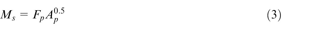
The surface finish component was calculated as the surface finish percentage factor multiplied by the sum of the points of the projected area and geometrical complexity. 13 The tolerance level was found by multiplying the tolerance percentage factor by the geometrical complexity points. Since no texture pattern such as checkers or leather grain were used on any of the parts, the mold manufacturing hours were zero for the texture component. Finally, the parting plane hours were calculated using equation (3), which used the projected part area (Ap) and the parting plane factor (Fp) 13
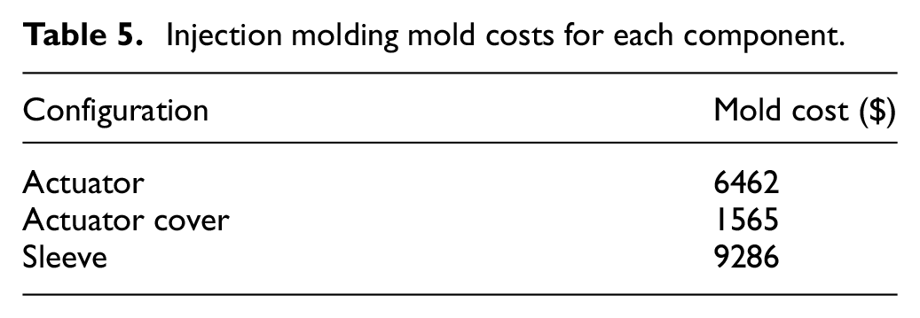
The mold cost point system was used for each part to calculate the total mold hours required. The cost was obtained by multiplying the total time required by the mold labor rate $40 per hour. 11 These results are summarized in Table 5. It was assumed that only one mold is required to produce the number of parts required for this application.
Injection molding mold costs for each component.
3D printing (SLS)
For the 3D printing process, a cost model developed by Ruffo estimated manufacturing time based on model geometry. 15 The model was broken down into three constituent parts: recoating time (tz), scanning time (txy), and pre/post processing time (tHC).
The recoating time (tz) is composed of the time that the machine needs to add layers of powder between successive layers. The gradient for the recoating time is based on the time to reposition the laser to a bed corner after scanning the build section. This gradient is a factor of the external packing ratio (Pr) shown in equation (4)
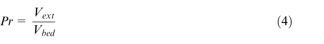
This factor is a ratio of the volume of the geometrical box containing the entire part divided by the volume of the entire machine bed. The geometric boundary box can be viewed as the minimum dimensions for a rectangular solid to envelope the part. Based on empirical data for the 3D Systems Vanguard SLS machine, the recoating time can be calculated by equation (5), where z is the height of the part. This equation was approximated using several part geometries and comparing their estimated recoating time versus the actual recoating time. 15 Part geometries tested included spheres, cubes, chain links, and swept solids.

The scanning time is highly variable as it is based on the part shape, but an approximate function was developed by Ruffo that estimated the time with a slight overestimation (equation (6)). 15 In order to obtain this equation, three approximations took place. The first approximated the worst-case scenario of a part that had the same base as the entire machine bed surface, and so estimated the time to scan the entire bed. The second approximation estimated the time to create a boxed volume that approximated the size of the part, without the detailed undercuts or internal voids. This over approximation was then refined through experimental analysis to result in the final equation shown below 15

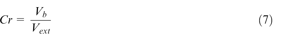
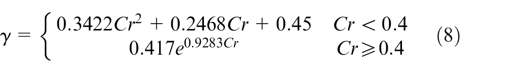
The scanning time is based on the bounding box of the part’s external geometry along with the compact ratio (Cr) given by equation (7) as the ratio of the part volume (Vb) by the part geometric bounding box volume (Vext). Based on the value computed for the compact ratio, two different relationships may be obtained to connect the part volume and bounding box volume highlighted by the variable gamma (γ) in equation (8)
Finally, the third element of the total build time equation is the pre/post processing time, which is based on the heating and cooling times required for the part. The two processes are constant and are normally evaluated by a time of 60 min or 3600 s.
The total build time was approximated for each part and the cost was obtained by multiplying the total time by the assembly cost of an hourly wage technician obtained at $18 per hour. 11 These results are shown in Table 6. The last row in the table shows the cost for creating the entire FO as one component instead of creating each part separately.
Selective laser sintering costs for different configurations.
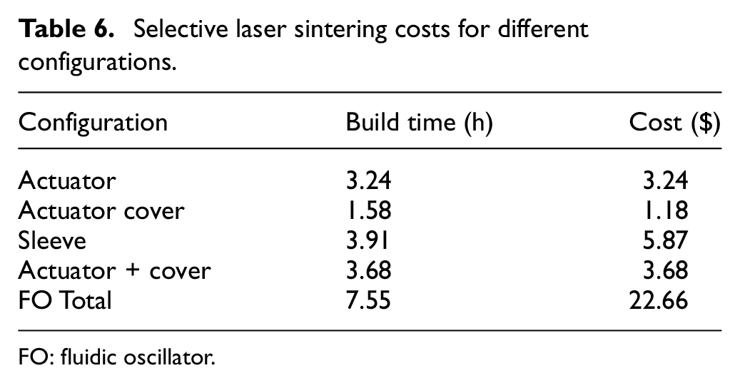
FO: fluidic oscillator.
Material and assembly
Material cost was calculated as the product of the cost of the material and the weight of the part. For 30% CF PEKK material, the cost was taken as the average material rate of $28.3 per kg taken from CES Edupack. 16
The assembly cost was segmented into the handling time and insertion time. The handling time consists of the time to grasp and manipulate a part without the aid of a grasping tool. This is highly dependent on part symmetry, which is broken up into alpha and beta symmetry. 13 The insertion time depended on factors such as the axis of insertion, visual obstructions to the insertion, part thickness, and ease of alignment. Both the handling and insertion times used predetermined time standard systems for assembly times in industry to come up with estimates.
Design configurations
After compiling the data for the cost of each part, the total oscillator costs were calculated for each possible manufacturing combination depending on if it was manufactured by IM or SLS. The design configurations are listed in Table 7.
Design configurations.
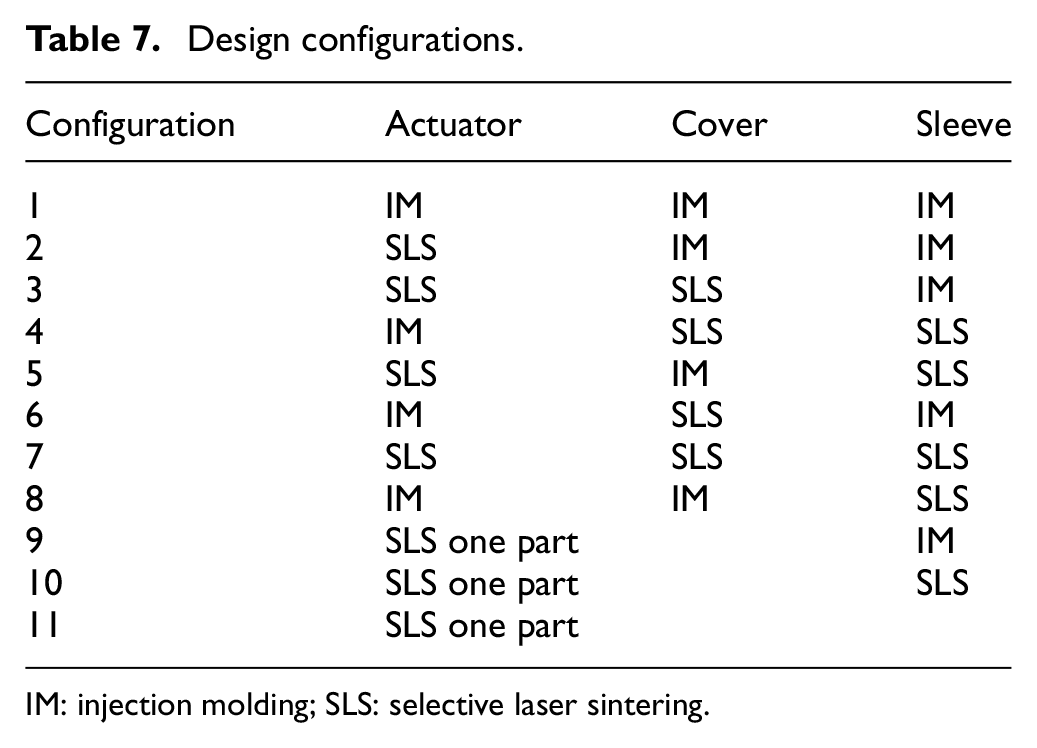
IM: injection molding; SLS: selective laser sintering.
The total cost is a function of the number of parts produced, as well as other factors. For 3D-printed components, there was also the variable manufacturing cost associated with printing each individual part. For the IM configurations, there was the fixed mold cost along with the variable assembly cost per part. Thus, for IM parts, the cost continued to decrease as the number of parts produced increased. A comparison of these design configurations is shown in Figure 8. Here, the unit cost is compared based on the number of FO produced from 0 to 10,000 parts. As can be seen, the IM parts begin with a large initial cost before decreasing to under $40 per part after about 1000 parts. This is highest for Configuration 1, which consists of all IM parts and thus requires three separate molds to be manufactured. Configuration 7, which has all 3D-printed parts, is depicted by the horizontal line. There is a horizontal trend as the number of units produced doesn’t change the FO unit cost. Configuration 1, which starts off with the highest initial cost, results in the most cost-efficient configuration with production needs of higher than 4550 parts. Configurations more reliant on 3D printing level off at higher unit costs, as with Configurations 5, 7, 10, and 11.
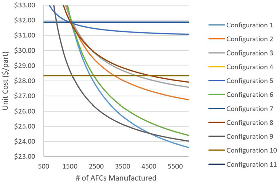
Fluidic oscillator cost versus part count.
It should be noted that although Configuration 1 yielded the lowest cost, Configuration 6 was a close second, which had used IM for both the actuator and the sleeve, but SLS for the cover. This is understandable, as the actuator and sleeve are both more complex and larger parts that take more time to print and thus result in a large manufacturing cost. On the other hand, the cover is a small, thin part without complex geometry and so its low printing cost is similar to its IM manufacturing cost due to the large initial mold cost. It should be noted that as more than 10,000 parts are produced, the difference in cost between the IM and SLS-printed cover parts becomes more apparent.
By comparing the unit costs of the different FO manufacturing configurations based on the number of parts produced, a decision can be made on which configuration to use. For any number of parts less than 1600, Configuration 10 should be used, in which the actuator and cover are one SLS part and the sleeve is produced separately. This configuration prints at a fixed cost of $28.35 per part. For a part number greater than 1600 but less than 4550, Configuration 9 should be used, which creates the actuator and cover as one SLS part and then uses IM for the sleeve. At the lower end of 1600, parts cost $28.35 and reduce to $24.53 for production closer to 4550 parts. For parts produced in excess of 4550, Configuration 1, which uses all IM parts, should be utilized to produce parts starting at $24.53, but reduces down to $22.43 at 10,000 parts.
On a commercial aircraft, several FOs would be needed to regulate air flow. Using this cost model, commercial aviation companies can make the decision on which configuration to use to manufacture the parts, based on the number of FOs needed.
Conclusion
This article presented the design of an AFC device that is integrated into a composite aircraft structure to improve air flow. A cost analysis was conducted to compare different design configurations. If FO part production is less than 4550, then a combination of SLS printing and IM should be used. However, if a greater number of parts are needed, then IM should be used to create all the parts.
Footnotes
Declaration of conflicting interests
The author(s) declared no potential conflicts of interest with respect to the research, authorship, and/or publication of this article.
Funding
The author(s) disclosed receipt of the following financial support for the research, authorship, and/or publication of this article: The authors are grateful for the funding and support received for this project from The Boeing Company as part of Georgia Tech-Boeing Strategic University Partnership.