
Abstract
Due to small production volume in aircraft industry, the available information of variation sources is often not enough to make assumptions on their probabilistic characteristics, especially in the stage of prototype manufacturing. To deal with the problem, an assembly variation modeling and analysis method based on the elasticity mechanics and interval approach is proposed for aircraft assembly. First, variation sources are modeled as bounded convex sets, which are defined as interval structural parameters in interval arithmetic. Then, variation modeling and analysis are successively implemented using the method of influence coefficient and interval arithmetic. After that, a uniform-splitting method is applied to achieve the refinement of the interval extension in variation analysis. To reduce the complexity of the finite element analysis and assembly variation computation, part deformation forms including warpage and torsion are concisely characterized with angle instead of the deviations of isolated key points on the part. The comparison of the assembly variations estimated with the proposed variation analysis method and actual experiment results verifies the effectiveness of the constructed assembly variation model and the proposed method. The interval approach–based assembly variation analysis method is a good complement to traditional probabilistic approach–based methods for compliant assembly systems, which is suited for linear and linearized nonlinear assembly systems. The proposed method provides an improved understanding of the application of compliant assembly variation analysis methods in aircraft manufacturing.
Keywords
Introduction
Assemblies of compliant structures such as sheet metals and thin-walled structures are widely used in automobile and aircraft industries. However, a real compliant assembly system is generally not accurately coincident with its nominal computer-aided design (CAD) model regarding dimensions, positioning of the parts and fixtures, which leads to the assembly variation of the product. The out of tolerances of the key features regarding functionality have influences on the quality of the downstream and final products. Also, the coordination among parts in the assembly may be deteriorated, which induces assembly stress. Therefore, modeling and analysis of assembly variation are extremely needed for the assemblies of compliant structures, especially for aeronautical structure assembly with high-quality requirements, to avoid the influences.
Research on assembly variation modeling and analysis with regard to compliant structures first appeared in automobile industry. Takezawa 1 pointed out the difference between flexible assembly and rigid-part assembly. And the difference is that in flexible assembly the assembly variation can be smaller than part variations. Afterward, Liu and Hu 2 proposed an offset beam element model to predict the assembly variation of a one-dimensional (1D) flexible assembly, which eliminates the overestimation in the assembly variation predicted with the rigid body assumption. To deal with two-dimensional (2D) and three-dimensional (3D) flexible assemblies, Liu and Hu 3 then developed a mechanistic assembly variation model integrating the finite element analysis (FEA), method of influence coefficient (MIC) and Monte Carlo simulation (MCS), which establishes a linear relationship between assembly variation sources and the assembly variation. As alternatives to the mechanistic assembly variation model, some other methods for assembly variation modeling and analysis are proposed. Shiu et al. 4 proposed a variation modeling method based on flexible beams for dimensional control, in which automotive parts are decoupled into beam components. Camelio et al. 5 used components geometric covariance along with the principle component analysis to estimate compliant assembly variation. Liao and Wang6,7 developed two assembly variation analysis methods with fractals and wavelets for compliant assemblies. Xing and Wang 8 introduced an assembly variation analysis method for sheet metal parts based on the method of power balance. Furthermore, the modeling and analyzing of the variation propagation in automotive assembly are studied in the literature.9,10 In addition, the effects on compliant assembly variation of many factors are studied, such as joint,11–15 assembly sequence,16–19 material characteristics20–22 and gaps.23–25 Recently, the research on variation modeling and analysis concerning compliant assembly has been extended to aircraft industry. Zhao et al. 26 presented the metamodel and simplified design simulation methods to move variation analysis into the early design state of aircraft. Lee et al. 27 provided a procedure for variation analysis of complex assemblies in aircraft industry, in which the datum flow chain, commercial 3D variation analysis and FEA are used. Saadat et al. 28 performed the modeling and analysis of an airbus wing box assembly. Liu et al. 29 developed an assembly variation analysis and prediction method for the riveting assembly of aircraft fuselage panels, in which the FEA, MIC and MCS are used. Wang 30 conducted riveting sequence study to control the deformation of a horizontal stabilizer. Also, variation source identification, deformation analysis and highly efficient selective assembly methods using FEA in horizontal stabilizer assembly are proposed.31–33 Cheng et al. 34 developed an elastic structure model based on beam elements for the variation modeling of fuselage structures in large aircraft digital assembly. Yang et al. 35 developed an optimization technique, which minimizes eccentricity stage by stage, to control variation propagation in the assembly of an aero-engine. In addition, Cheng et al., 36 Zhang and Shi 37 and Zhang et al. 38 modeled and analyzed the variation propagation in the assembly of aeronautical thin-walled structures.
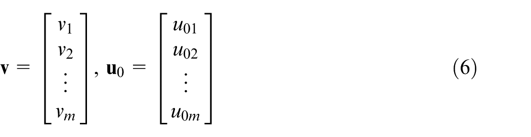
In the literature, assembly variation models constructed with various theoretics, and the impacts of many variation sources on the assembly variation, are studied for compliant assembly systems. In contrast, the available information regarding variation sources is rarely paid attention to because the probabilistic characteristics of the variation sources are always assumed to be known. As a probabilistic approach, the MCS is often integrated with the mathematical relation between the assembly variation and variation sources to analyze the assembly variation. However, due to the small production volume of aircraft industry,39,40 the available information regarding the variations of parts and fixtures in aircraft assembly is often not enough to make assumptions on their probabilistic characteristics, especially in the prototype manufacturing stage. In addition, a frequently occurred case in industrial production is that the only known information of a variation source is its tolerance interval rather than the probabilistic distribution. Although process designers could assume that each variation source variable is normally distributed with 6σ limits equal to the tolerance interval, the transition from the tolerance interval to the parameters of the normal distribution is insipid. And in the case of a nonnormal distributed variation source, the assumption may deteriorate the reliability of assembly variation analysis. Moreover, the rejection rate in aircraft industry is controlled very strictly because of high invested capital. Thus, the 6σ criterion used in automobile industry with the rejection rate of 0.27% is high in aircraft manufacturing to some extent.
Considering the discussion above, an intuitive and realistic assembly variation analysis method based on interval approach is developed to predict the assembly variation of compliant aeronautical structures. Interval approach originally developed by mathematicians is a numerical method, which puts bounds on rounding and measurement errors and yields reliable results in mathematical computation. Interval approach presented a natural way to directly incorporate uncertainties into a calculation by operations of interval arithmetic. Interval approach has been used successfully in the field of mechanical engineering. Lee et al. 41 performed the geometric design of serial-link robot manipulators including three revolute joints using interval approach. Hao and Merlet 42 proposed a methodology based on interval approach for parallel manipulators’ optimal design with multi-criteria requirements. Wu and Rao 43 presented the application of interval approach for tolerance and clearance modeling in mechanism analysis. Merlet 44 solved the forward kinematics problem using interval approach for a Gough-type parallel robot. Oetomo et al. 45 proposed a complete workspace analysis technique based on interval approach for a planar flexure-jointed mechanism. Merlet 46 developed a trajectory verifier based on interval approach for the motion planning of a classical Gough–Stewart platform. In the developed variation analysis method based on interval approach, variation sources are first assumed to be in bounded convex sets and formatted as interval structural parameters. To characterize the overall deformation of the parts being assembled, warpage and torsion angles are used instead of the displacements of key points such as fastening points. Then, interval arithmetic permits us to intuitively compute the interval of the assembly variation using the operation of the interval arithmetic and the assembly variation model obtained with the MIC. Change in assembly sequence has influence on the assembly variation to some extent.16,17 In this article, an empirical assembly sequence, obtained from actual wing assembly in an aircraft factory, is used. The proposed assembly variation analysis method is a good complement to the traditional counterparts based on probabilistic approach, which is well suitable for linear assembly systems. It will not work for a high-order nonlinear assembly system unless the nonlinear assembly variation model is linearized using Taylor expansion or other linearization techniques. Also, the proposed method can be used for rigid-part assembly by combining with linear or linearized assembly variation model.
The rest of this article is structured as follows: In section “Assembly variation model represented with interval approach,” a general assembly variation model represented with the interval approach is provided. In section “Assembly variation modeling and analysis with interval approach,” the assembly variation model of compliant aeronautical structures using the MIC is discussed. Also, the assembly variation analysis method based on the interval approach, and the refinement of the interval extension, is presented in this section. To verify the correctness of the constructed assembly variation model and the effectiveness of the proposed assembly variation analysis method, the numerical simulations and actual experiments of the assembly process of a simulant wing skeleton have been performed in section “Wing skeleton constructed with compliant structures.” Finally, conclusions are drawn in section “Conclusion.”
Assembly variation model represented with interval approach
In production, tolerances rather than probabilistic characteristics in terms of variation sources are often known, which are natural intervals with lower and upper bounds. Therefore, it is assumed that the variation sources fall into the bounded convex sets which are interval numbers.47–50 The assembly variation is calculated making use of the interval arithmetic. And the assembly variation model is represented with interval approach. 51
In this article, we use closed interval

An interval number

where
It is assumed that interval numbers
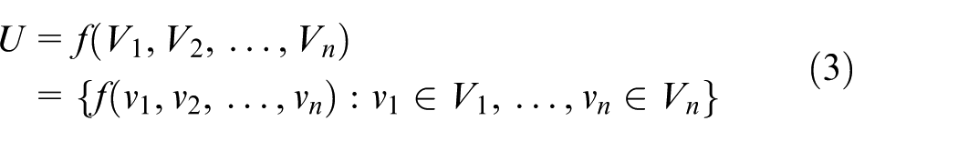
The formula above is an instance of the function of interval variables. The assembly variation model
In the interval arithmetic, the solving of the assembly variation response


A review of the basic operations of the interval arithmetic is provided in Appendix 1. Furthermore, an interval vector or matrix is defined as the vector or matrix with interval components. Arithmetic operations on interval vectors and matrices with respect to interval numbers are similar to real vectors and matrices operations regarding real numbers. The detailed arithmetic operations of interval vectors and matrices are provided in the literature.47–50 Thus, tolerances valued by intervals in industrial applications can be intuitively operated with the interval arithmetic.
Assembly variation modeling and analysis with interval approach
Assembly variation modeling of compliant aeronautical structures
An assembly process of compliant aeronautical structures generally includes four steps including Positioning (
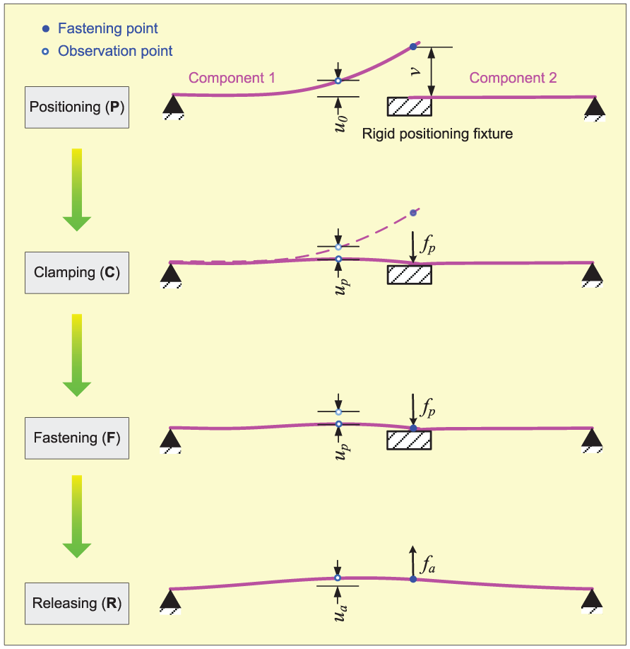
Assembly process of compliant aeronautical structures.
For assembly variation analysis of complex 2D or 3D compliant aeronautical structure assemblies, such as a simulant wing skeleton shown in Figure 2, the mechanistic assembly variation model based on the MIC is often used. Due to manufacturing and positioning errors of the components to be assembled, fastening points often deviate from their nominal positions. Thus, variations
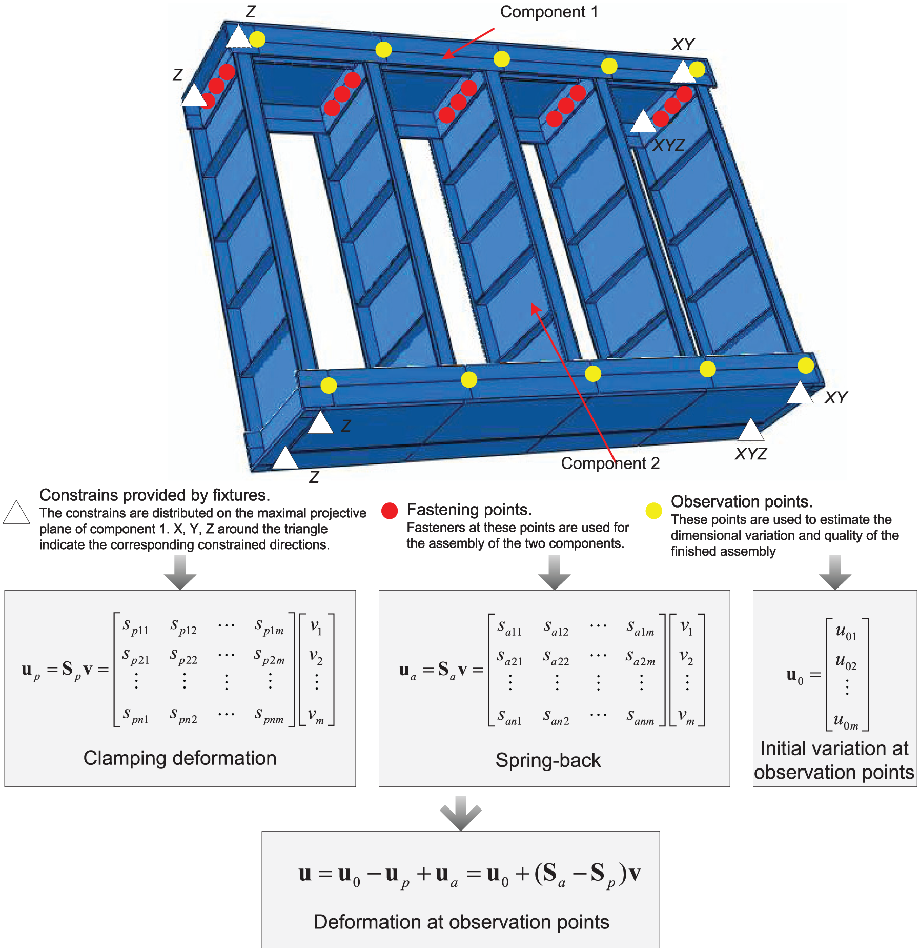
Assembly variation analysis of two aeronautical compliant structures.
In the compliant assembly process, the clamping deformations at the fastening points often result in the displacements of the observation points. However, the clamping at a fastening point does not always bring an observation point to its theoretical position. The sensitivity matrix
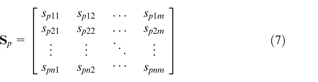
After assembly, the FEA is also applied to produce the sensitivity matrix

The final variations

where
For the assemblies of large compliant aeronautical structures, besides the variations of components matching features, temperature fluctuation and gravity also induce the assembly variations at the observation points. For simplicity, the effects of the variation sources can be linearly superimposed. Thus, equation (9) can be rewritten as

where
Assembly variation analysis with interval approach
In assembly variation analysis of compliant structures, part deformation is generally represented by the variations of key points distributed on the part. But this representation cannot intuitively describe the overall deformation, such as warpage and torsion, of the part. Liu et al. 29 attempt to apply angle measurement to represent the flange deviation and torsion regarding clips and frames used in aircraft manufacturing. In this section, warpage and torsion angles are used as the measurement of the warpage and torsion of parts, respectively. Thus, the values of variation sources extend from the displacements of points to the warpage and torsion angles. An instance of part deformation represented with warpage and torsion angles regarding a compliant aeronautical structure, wing rib, is illustrated in Figure 3.
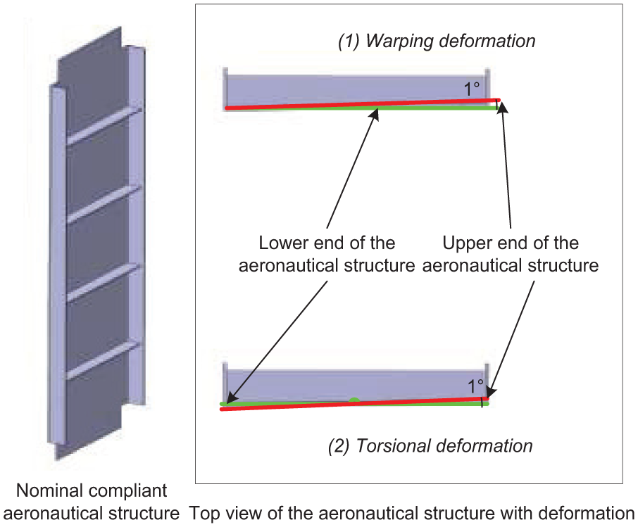
Instance of part deformation represented with angles.
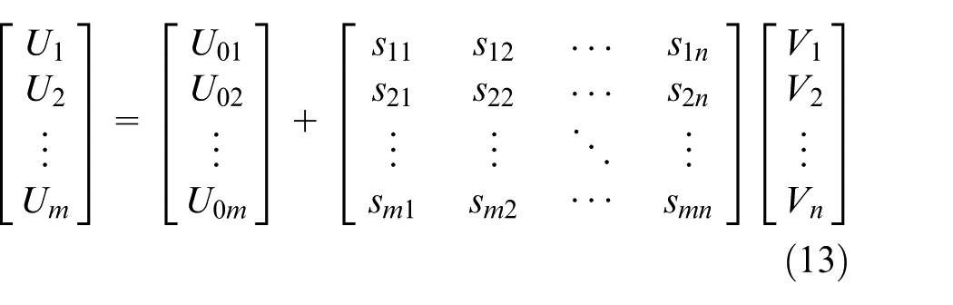
When the probabilistic distributions of variation sources such as the warpage and torsion angles of compliant aeronautical structures are unknown, an alternative assembly variation analysis method based on the interval approach is proposed using equation (3) in section “Assembly variation model represented with interval approach.” And equation (10) is extended to interval structural parameters

where
If the effects of temperature fluctuation and gravity on the assembly variation are not considered, the terms of

The full expression of equation (12) is given as below
where the deviations
Refinement of interval extension
In case the only known information about the contributors to assembly variation is tolerance ranges instead of probabilistic distributions, the assembly variation model

where
This phenomenon results in an overestimation of assembly variation in real applications. Therefore, a uniform-splitting method is applied to obtain the sharp bounds of the assembly variation. The intervals
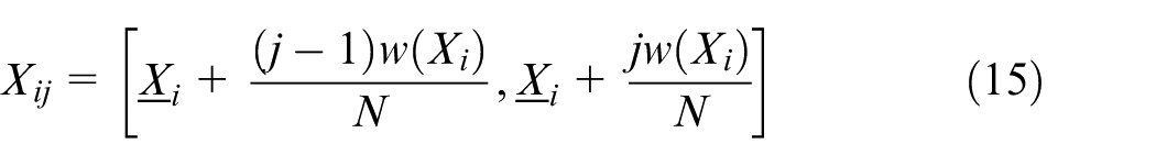
where
The union of the interval estimations of the assembly variation model over the split subintervals

Wing skeleton constructed with compliant structures
Assembly process of wing skeleton
In this section, a simulant wing skeleton is used to demonstrate and verify the proposed assembly variation analysis method based on the interval approach. During the assembly process of a wing box in aircraft manufacturing, rear spar, front spar and wing ribs are first constructed as a ladder structure called wing skeleton using a gantry-based main assembly jig, which is shown in Figure 4. First, the rear and front spars are positioned on the jig and coordinated with each other. Second, the wing ribs are fastened to the rib posts distributed on the rear and front spars. The locating schemes of the components of the wing skeleton are coincident with what generally used in compliant assembly.
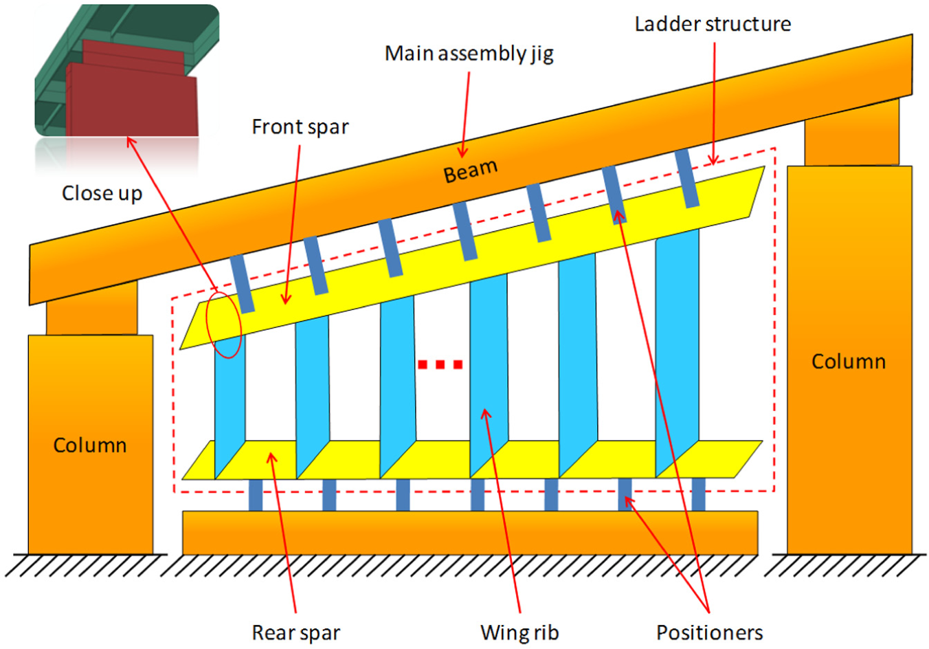
Assembly scheme of a wing skeleton in aircraft wing manufacturing.
As a compliant slice structure, a wing rib often has warping and torsional deformation. The installation of a wing rib follows the
Introduction of object of study
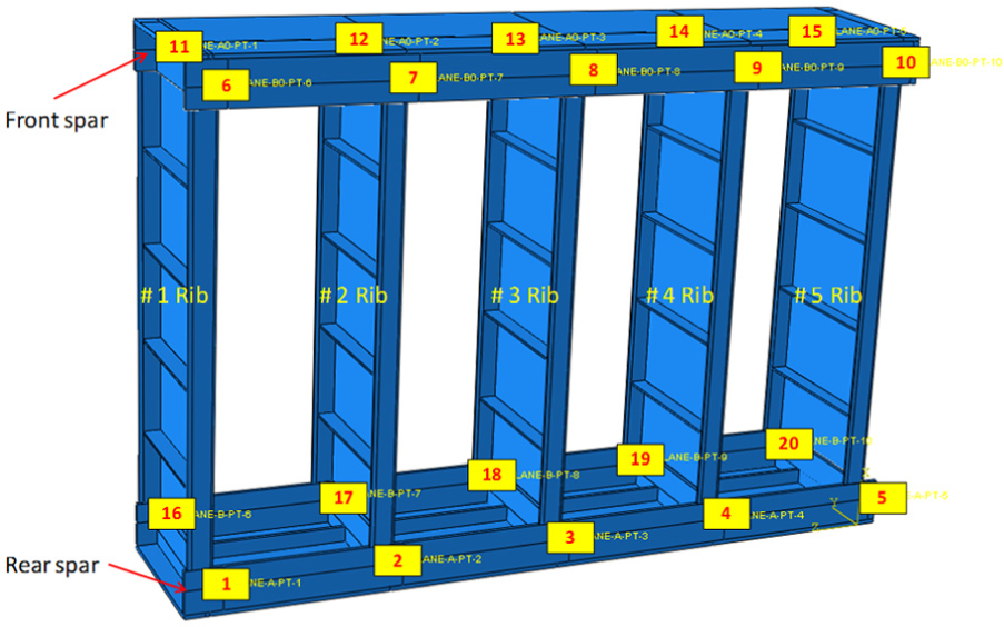
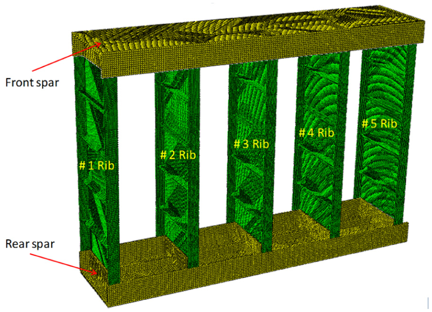
In this case study, a simulant wing skeleton shown in Figure 5 is used as the object of study. The maximal cross section and the thickness of the skeleton are 850 mm × 600 mm and 200 mm, respectively, and the rib spacing is 200 mm. The spars and ribs are 5 mm and 2.5 mm in thickness, respectively, along the normals of their maximal projective planes. All components are manufactured with Al 2A12. The FEA of the assembly process of the simulant wing skeleton is conducted in software Abaqus® 6.10. The FEA model of the simulant wing skeleton is shown in Figure 6, in which the element type C3D8R is used to mesh the components. In assembly variation analysis, the stress–strain relationship is assumed to be in the linear range.
Simulant wing skeleton used in the case study.
FEA model of the simulant wing skeleton.
In the assembly of the simulant wing skeleton, many variation sources could induce the assembly variation, among which the warpage and torsion of the ribs illustrated in Figure 3 are two important types. Thus, it is assumed that there are 10 variation sources related to the five ribs. The warping and torsional deformations are characterized by the warpage and torsion angles, the ranges of which are all [−0.6°, 0.6°] in interval format. The intervals with respect to the manufacturing errors of the spars at observation points are all [−0.5 mm, 0.5 mm]. Since wing skeleton assembly is the preparation for the subsequent processes of wing box assembly, the assembly variation of the wing skeleton should be controlled in the required tolerance interval to ensure the quality of the finished wing box. In this case study, the observation points’ variations along the normal of the spars’ flanges are focused on because the variations have significant impact on the subsequent wing panel installation. In total, 20 observation points are distributed on the simulant wing skeleton to evaluate its assembly quality, refer to Figure 5.
Assembly variation analysis for simulant wing skeleton
During the assembly of the simulant wing skeleton, the positioning, clamping, fastening and releasing processes of a wing rib with deformation are shown in Figure 7. Due to the warpage and torsion of the ribs to be assembled, not all fitting features of the ribs can exactly match with the corresponding rib posts. Thus, in positioning and clamping processes, a deformed rib is first prepositioned to make one group of the features of the rib and rib posts be fitted. Then, a fixture is applied to fix the nominal joining position. After that, a clamp is used to conquer the deformation of the deformed rib and close the misalignments between the other group of the features of the rib and rib posts. In detail, the end without deformation of a deformed rib is preplaced against and joined with the corresponding rib post and then the other deformed end of the rib is clamped and fastened with the counterpart rib post. Due to the assembly force induced by the exerted clamping force in the assembly process, the deformed rib is inclined to be back to its initial deformed shape after the fastening operation and the removal of the clamp and fixture, and thus, the final assembly will spring back.
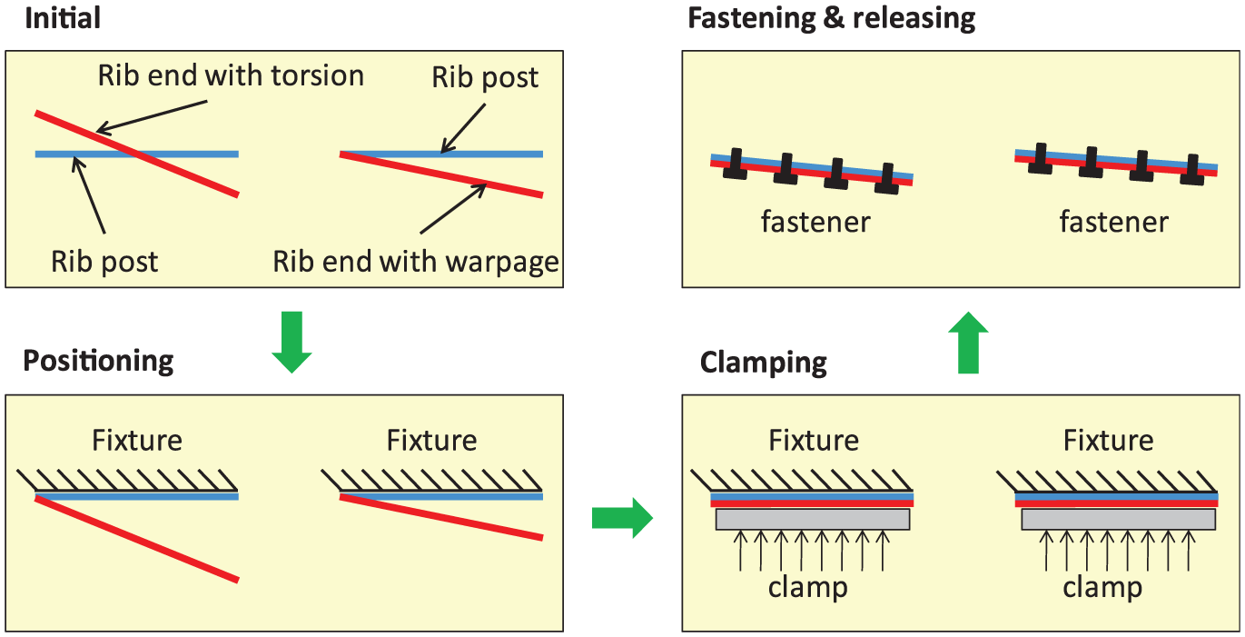
Positioning, clamping, fastening and releasing processes of a deformed wing rib.
Due to the small product size of the simulant wing skeleton, the effects of temperature fluctuation and gravity on the assembly variation are omitted. The assembly variation analysis process for the simulant wing skeleton using the proposed assembly variation analysis method in section “Assembly variation modeling and analysis with interval approach” is described as follows:
Step 1. Design the nominal spars and wing ribs, as well as the wing ribs with one angle warping or torsional deformation, using the software Catia® V5R19.
Step 2. Simulate the positioning and clamping processes of the wing ribs with warping or torsional deformation during the assembly process by the FEA executed in Abaqus 6.10. And Figure 8 is an instance for a rib with warping deformation.
Step 3. Model the processes of the joining of the wing ribs and the corresponding rib posts, as well as the assembly spring back by the FEA executed in Abaqus 6.10. And Figure 9 is an instance for a rib with torsional deformation.
Step 4. Obtain the sensitivity matrix
Step 5. Compute the assembly variation intervals of the observation points with the obtained sensitivity matrix
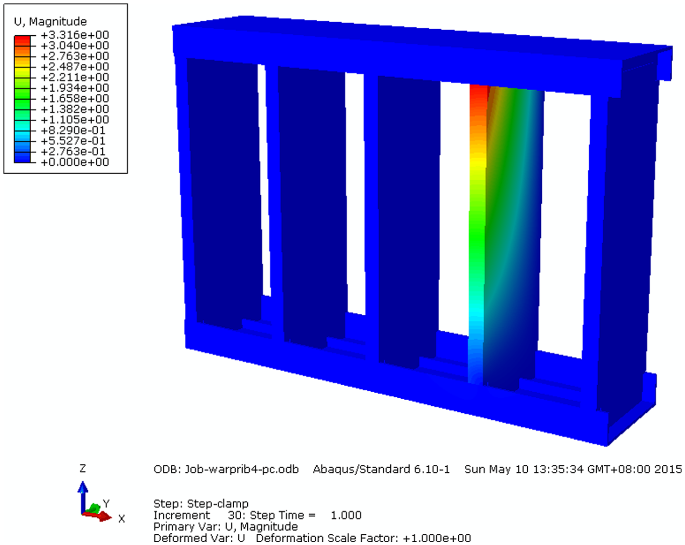
Simulations of the positioning and clamping processes by the FEA.
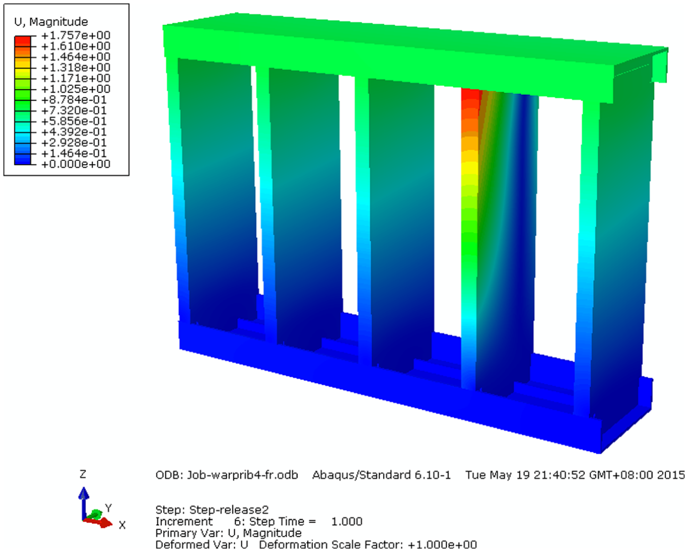
Simulation of the joining and spring back processes by the FEA.
In the assembly variation analysis process, the uniform-splitting method is used to obtain the sharp bounds of the assembly variation. With the increasing number of the subintervals
In experiments, mean verification 52 is used to verify the proposed method because only one assembly of wing skeleton is obtained. The measuring platform is shown in Figure 10, which consists of a Coord3 coordinate measuring machine (CMM), a simulant wing skeleton constructed with ribs and spars, a computer for the CMM and so on. The assembly variations are measured by the Coord3 CMM. In actual experiments, the material of the simulant wing skeleton is in accordance with the counterpart in numerical simulation above.
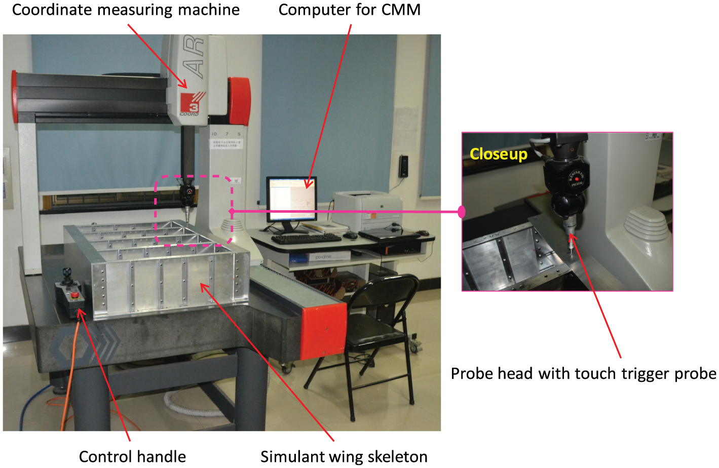
Measuring platform of the assembly of the simulant wing skeleton.
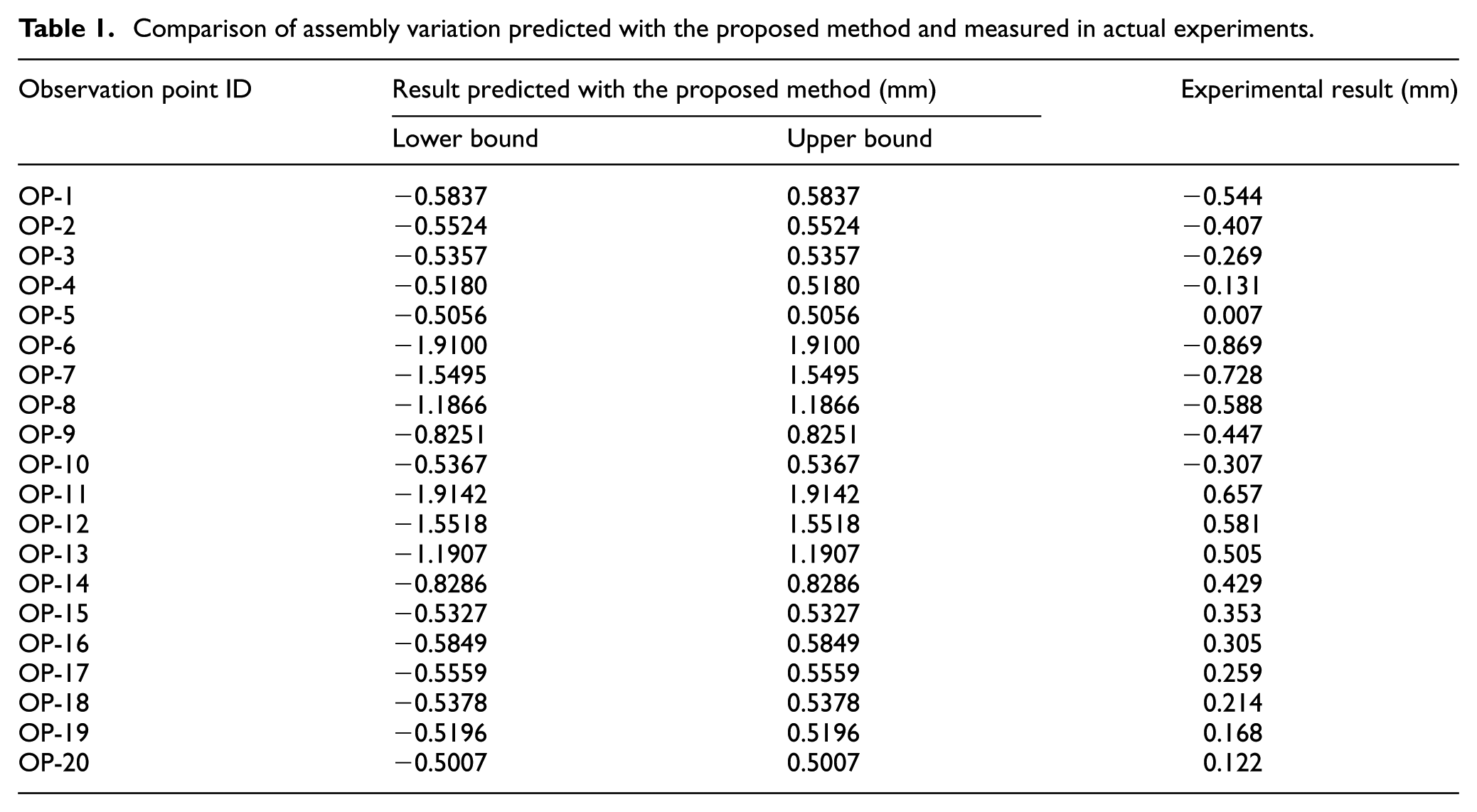
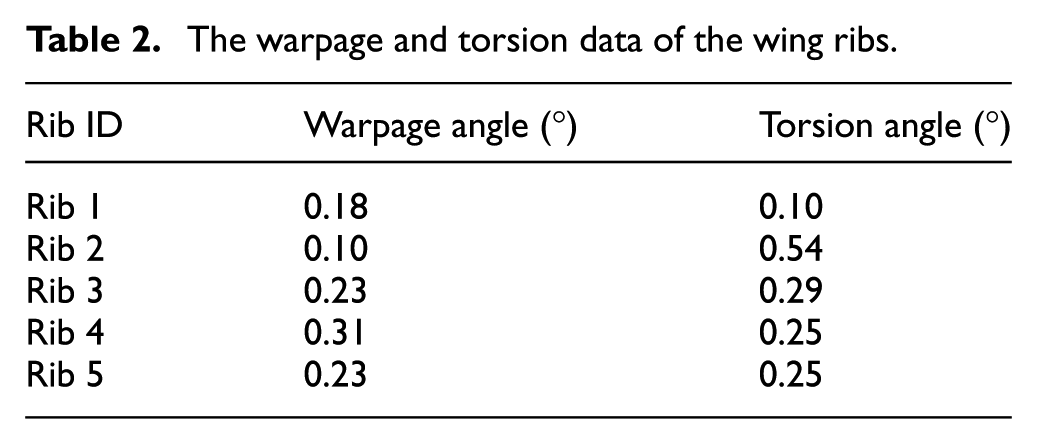
The comparison of the actual experimental results and the numerical results obtained with the assembly variation analysis method based on the interval approach is shown in Table 1. The warpage and torsion date of the wing ribs is provided in Table 2. It can be concluded that the actual and numerical results fit with each other, which reveals that the constructed assembly variation model and proposed assembly variation analysis method are efficient.
Comparison of assembly variation predicted with the proposed method and measured in actual experiments.
The warpage and torsion data of the wing ribs.
Conclusion
In this article, a novel assembly variation analysis method based on the interval approach and the MIC is proposed for the assembly of compliant structures in aircraft manufacturing. Variation sources are modeled with interval structural parameters. The assembly variation is computed based on the interval structural parameters, the assembly variation model constructed with the MIC and the interval arithmetic operations. To achieve the refinement of the interval extension in variation analysis, a uniform-splitting method is applied. The proposed method can handle the problem that the probabilistic characteristics of variation sources are unknown, which frequently occur in aircraft production, especially in the stage of prototype manufacturing. To reduce the complexity of the FEA and assembly variation computation, part deformation such as warpage and torsion is concisely characterized with angle instead of the deviations of isolated key points on the part. The comparison of the assembly variations estimated with the proposed assembly variation analysis method and actual experiment results verifies the effectiveness of the constructed assembly variation model and the proposed method. The interval approach–based assembly variation analysis method is a good complement to traditional probabilistic approach–based methods for compliant assembly systems, which provides an improved understanding of the application of compliant assembly variation analysis methods in aircraft manufacturing.
Footnotes
Appendix 1
The basic arithmetic operations of interval numbers are defined as below. The key to these definitions is that computing with interval numbers is computing with sets.
The resulting interval number of the adding of two interval numbers
The difference of the two interval numbers is given by
The product of the two interval numbers
The quotient of the two interval numbers
provided
Declaration of conflicting interests
The author(s) declared no potential conflicts of interest with respect to the research, authorship and/or publication of this article.
Funding
The author(s) received the following financial support for the research, authorship, and/or publication of this article: This research was supported by the Science Fund for Creative Research Groups of National Natural Science Foundation of China (Project No. 51221004) and National Natural Science Foundation of China (Project No. 51675479).