
Abstract
There are various processes practiced in a market for manufacturing axisymmetrical cup with significant forming depth among which deep drawing process is most prompt. The deep drawing process is a forming process with ongoing interest which will have a major impact on industries in coming years. This article focuses on the current status and potential of future development of technology in the deep drawing process. First, it describes various types of approaches and techniques used in the deep drawing of different materials. This is followed by brief reviews of advantages and limitations of these technologies with its application in industries. The details of these technologies are just referred rather than explaining in detail. The further part of this article focuses on advanced methods for predicting defects like thinning, wrinkling and spring-back in deep drawing process which are mostly responsible for rejection of the components. The opportunity in the development of flexibility in deep drawing process is covered with an observed barrier in the prediction of defects such as thinning, wrinkling and spring-back. The obtained evidence indicates that deep drawing process may not be applicable for all materials, but represents an excellent opportunity in the drawing of multilayer metal and composite material sheets to complex shapes.
Introduction
The deep drawing is a metal forming process used for manufacturing the axisymmetric component having measurable drawing depth. When the depth of component is significantly greater than its diameter, such components can be easily formed to the desired shape using deep drawing process. This sheet metal forming process is preferred in aerospace industries, automobile industries and kitchen utensil manufacturing industries.
When the component with a complex profile is drawn to a certain depth, it will lead to uneven distribution of thickness along the drawing direction. The thinning of the sheet is observed at the bottom of a component, whereas thickening is observed at the upper flange of the component. 1 The thinning is observed predominantly where the cup profile changes the direction, as it creates the obstacle in the flow of material while drawing. The different techniques which were used to eliminate the problem of thickness variation and material flow in the die cavity are briefed in this article. It is observed that the flow of material in die cavity depends on the surface finish of tools. The increase in surface finish increases the tendency of material flow which can be enhanced by selecting a proper type of lubrication. The effect of wet and dry lubrication can make a distinct difference in coefficient of friction. 2 The component achieved by maintaining above conditions will have a uniform thickness and better mechanical strength which has vast application in mechanical and electrical devices.
Another most common defect observed in forming process is wrinkling. The wrinkling defect occurs due to the application of uneven blank holding force. The blank holder is specifically used for maintaining a pressure on blank while performing a deep drawing operation. The excess application of blank holding force leads to tearing of blank at the die shoulder radius or punch nose radius, whereas low blank holding force leads to the occurrence of wrinkles at the flange region. 3
Apart from thinning and wrinkling effect, the spring-back effect is also observed frequently while performing deep drawing operation. It is difficult to obtain the exact required shape by forming process due to the behaviour of the material. In few cases, it is observed that when the punch retracts after drawing a required component, it slightly regains its original shape due to elastic property. This unwanted regaining of shape after removal of applied force can be called as a spring-back effect. The factors such as material anisotropy, punch angle, die lip radius and punch radius found to have more influence on spring-back effect. 4 To achieve a prescribed dimension of drawn component, spring-back effect should be accurately predicted and measurable actions should be taken.
The evidence obtained from recent reviews 5 which were carried out on deep drawing process indicated that the parameters such as temperature, friction coefficient, blank holder force (BHF), blank shape and punch speed had more influence on the quality of the product. However, these deterministic efforts neglect the effect of geometrical parameters such as punch and die radius, clearance and surface finish of tools and the brief discussion on defect caused due to these parameters while performing the process. Also, the comprehensive literature review conducted on optimization aspects in deep drawing process was limited to few techniques and approaches. The advanced techniques and approaches missed in recent review article are mostly included in this review.
From literature, it has been found that the recent research has been carried out on the deep drawing of multilayer and composite materials which have vast application in the field of automobile industries due to its lightweight and high strength. To maintain safety, the thickness variation in such advanced materials should be within the safer limit. This review article discusses the evidence of parameters which promote the defects such as thinning, wrinkling and spring-back effect for deep drawing of metals, multilayer metals and composite materials.
Thinning effect
The sheet metal forming processes need to be designed properly in order to achieve a successful forming of a component with complex profiles. Nowadays, consumer demands a quality product which can be fulfilled by adopting effective methods and techniques. The quality directly influences the defect such as wall thinning. Such defect can be analysed and predicted using theoretical, numerical and experimental approach.
Approach to predict thinning effect
Traditionally, the deep drawing was carried out using an analytical method and further validated by performing experimental tests. This method had been consuming more time and cost which can be reduced by introducing numerical technique. The effect of yield criterion on numerical analysis of reverse deep drawing process for mild steel sheet was investigated by Neto et al. 6 using Hill’48, Von Mises and Barlat Yld’91 theory combined with Swift hardening law. The evaluation of punch force and distribution of thickness along the cup wall was carried out for two deep drawing stages (see Figures 1–3). The predicted cup wall thickness by a numerical method for the second stage was higher as compared to the first stage. It was found that thickness distribution predicted by Hill’48-R and Yld’91 models were closer to experimental results.
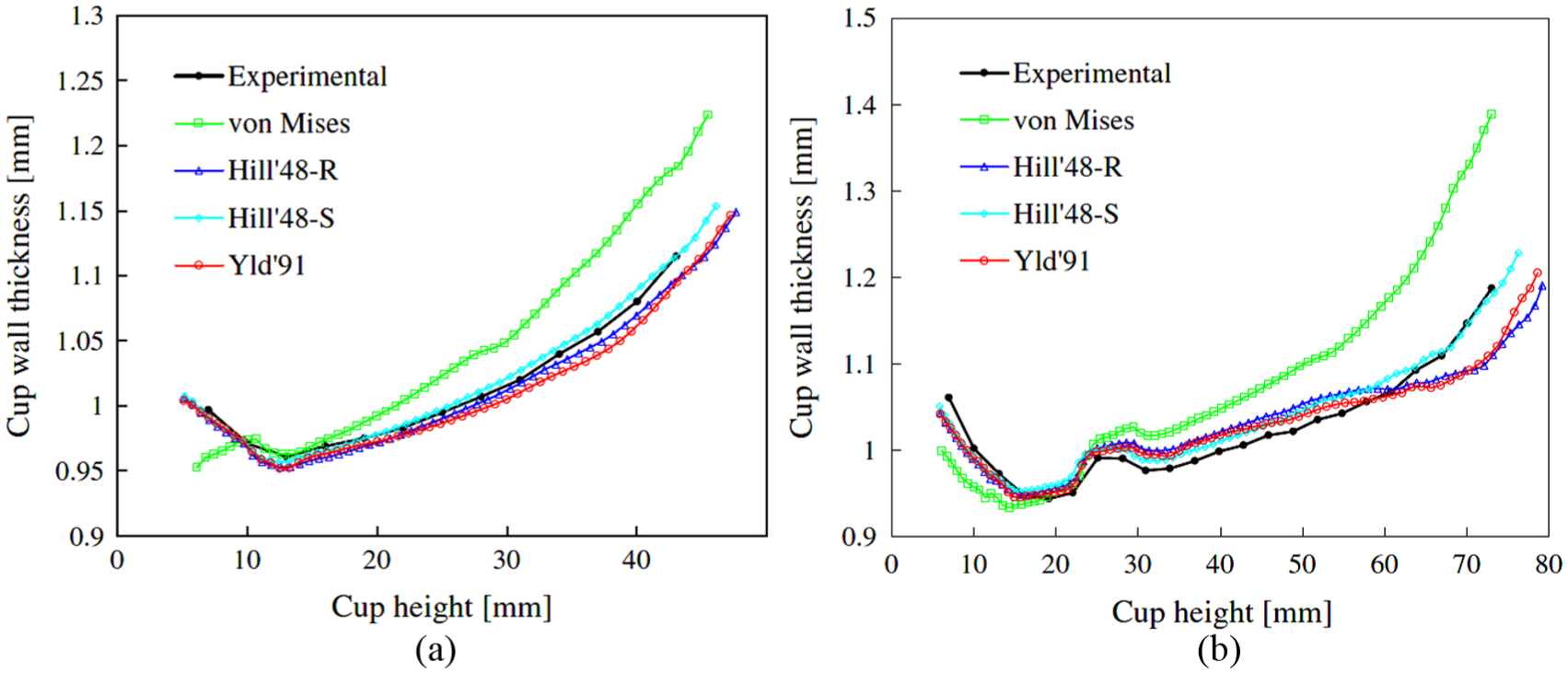
Thickness distribution in cup for rolling direction 0° after (a) first drawing stage and (b) second drawing stage. 6
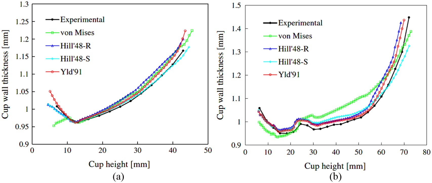
Thickness distribution in cup for rolling direction 45° after (a) first drawing stage and (b) second drawing stage. 6
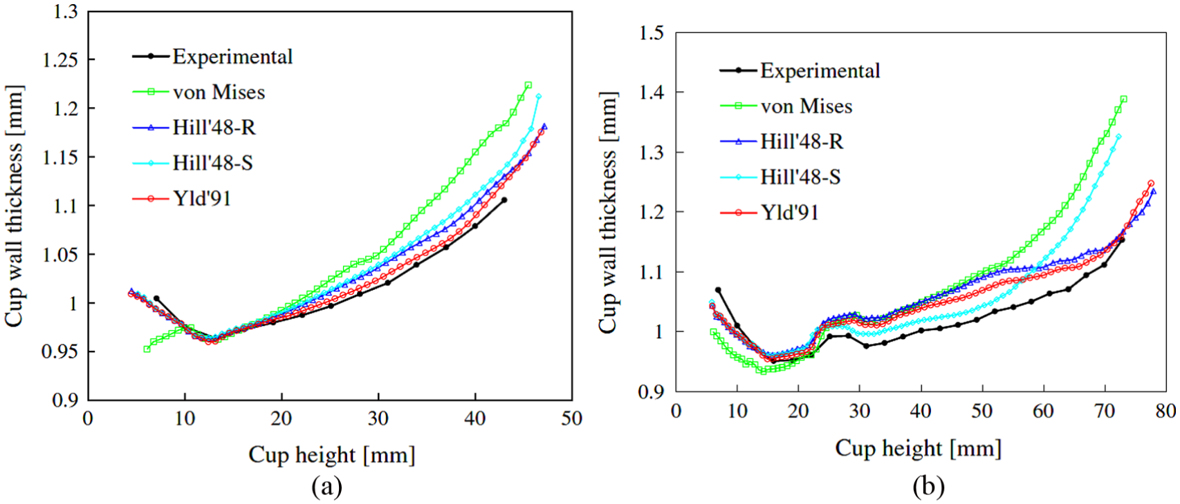
Thickness distribution in cup for rolling direction 90° after (a) first drawing stage and (b) second drawing stage. 6
Fereshteh-Saniee and Montazeran 7 calculated the force required for drawing complex profile component using analytical, experimental and numerical techniques and observed that the Siebel’s formula provides more accurate results of drawing force than numerical technique. In a case of numerical technique, it was found that Shell 51 element proved to be more effective for deep drawing process instead of Visco Solid 106 element (see Figure 4).
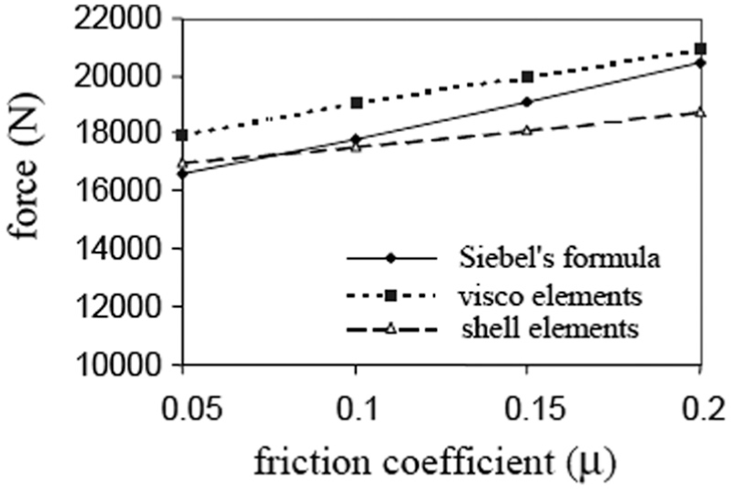
Drawing force variation with coefficient of friction for different methods. 7
The conical dies were developed by Dhaiban et al. 8 for deep drawing of a brass elliptic cup which involves punching of circular blank using a single stroke with a flat headed elliptical punch through a conical die having an elliptical aperture. The effect of punch and die geometry was investigated to optimize design process by performing numerical analysis on the three-dimensional model. From the experimental test, it was observed that half cone angle of 18° had best drawing ability, whereas the best limiting drawing ratio (LDR) was about 2.24–2.26. This technique has been proved to be convenient for drawing the sheet with the thickness between 1.9 and 3 mm by maintaining the thickness of cup along with major and minor axes for different clearance ratio (see Figure 5(a) and (b)). Also, Garcia et al. 9 carried out modelling and experimental tests for three different applications of deep drawing such as cylindrical cup test, Erichsen test and industrial sheet metal forming process for EK4 steel. The obtained numerical results for proposed model had less variation with experiential results which prove that the model can be effectively used to solve industrial problems.
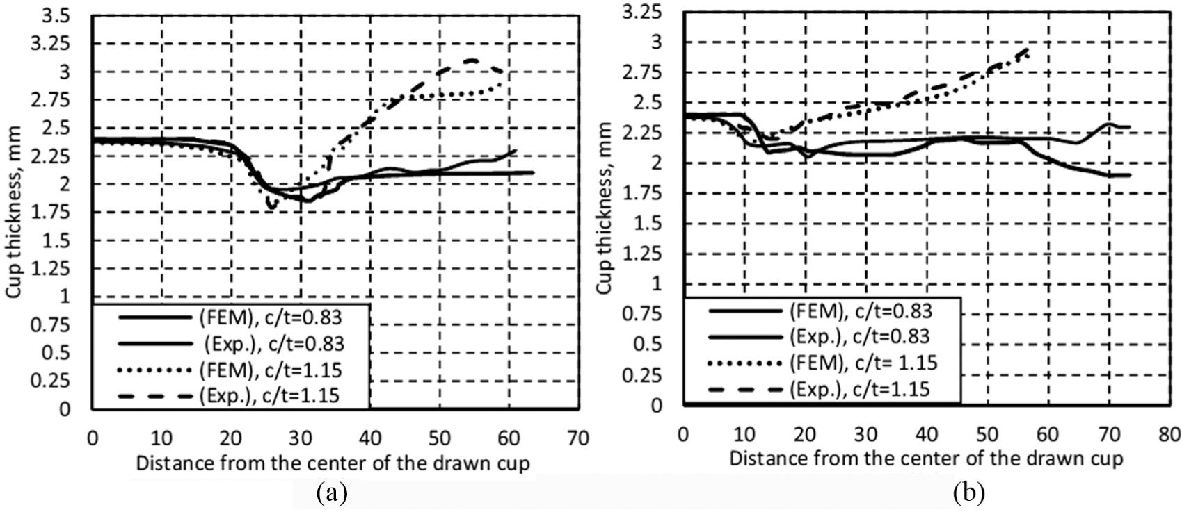
Effect of clearance ratio on cup thickness t = 2.4 mm at LDR (a) along major axis and (b) along minor axis. 8
The numerical approach is frequently used for the optimization and validation of deep drawing processes. The process optimization was carried out by Gantar et al. 10 for deep drawing of rectangular components using finite element method (FEM) to increase the stability of the process. The study focuses on input parameters such as die radius, punch radius, blank holding force, clearance, friction coefficient, restraining force of drawbead, drawing speed of punch and outcoming effects such as spring-back effect and thinning effect. Also, the FE simulation for deep drawing of axisymmetric cups with drawing depth 30, 18 and 6 mm was carried out by Natarajan et al. 11 to analyse the thickness distribution and plane principle deformation. The large-strain hyperelastic shell formulations which include Hill’48-associated model were used for numerical simulation of a cup. Along with the mentioned approaches, the artificial neural network (ANN) can also be used for the optimization of process parameters. The blank optimization using ANN was carried out by Haddadzadeh et al. 12 for deep drawing of a circular cup. The numerical and experimental approach was used to simulate the deep drawing process. The neural network method was observed to be quicker, be accurate and provide a solution in single step than sensitivity analysis method. The obtained optimum blank had a less thinning effect and uniform deformation in drawn part which reduces the failure possibility.
Effect of parameters on thinning
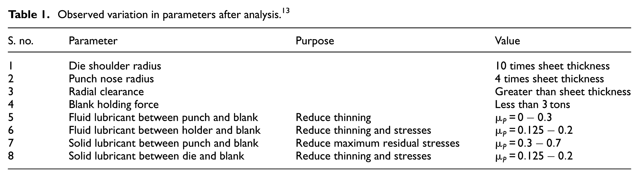
The parametric study is carried out for optimization of deep drawing process to minimize the thickness variation. El Sherbiny et al. 13 carried out parametric analysis to investigate the thinning and residual stresses in deep drawing process of sheet metal (see Table 1). The explicit analysis was performed on a three-dimensional model by considering anisotropic material properties to predict thickness distribution, residual stresses, geometrical and physical parameters.
Observed variation in parameters after analysis. 13
Padmanabhan et al. 14 implemented the Taguchi method for identification of relative influence of process parameters such as BHF, friction coefficient and die radius on a deep drawing of axisymmetric stainless steel cup. The predicted thickness distribution revealed that the die radius had a greater influence on deep drawing process than blank holder and friction coefficient. The effects of parameters such as thinning, punch load, the angle of U part and surface quality on micro U deep drawing were investigated by performing experimental tests 15 (see Table 2).
Effect of change in parameter for micro U deep drawing process. 15
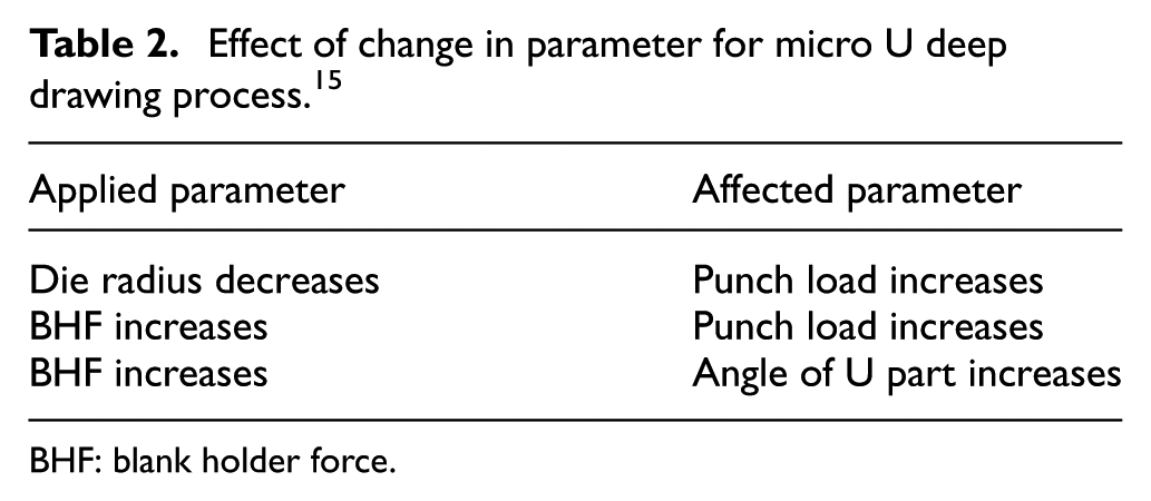
BHF: blank holder force.
Lubrication conditions
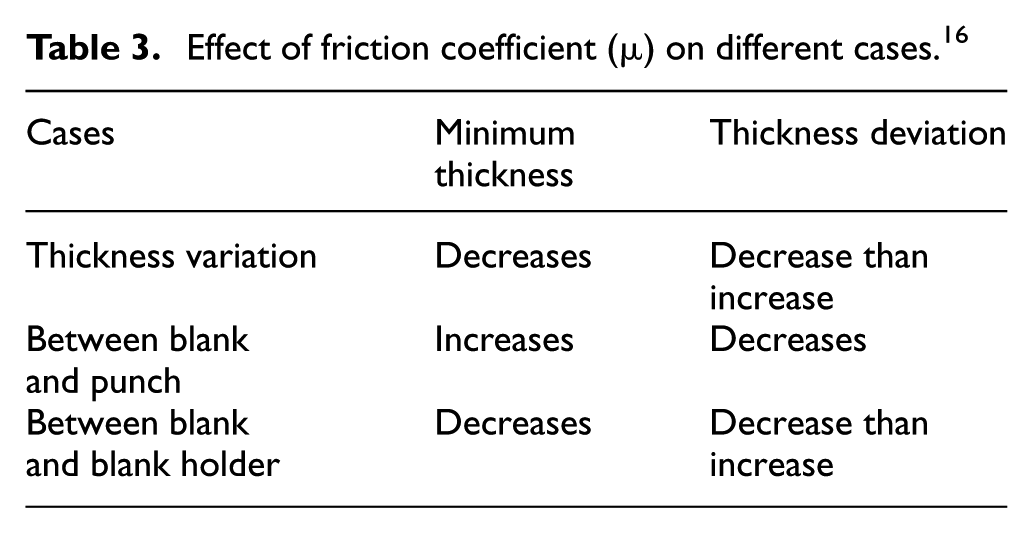
The different types of lubricant can be used for reducing friction between blank and tooling while performing deep drawing process. Due to inadequate and improper lubrication condition, defects such as thinning, tearing and scratching are generated. Ma et al. 16 investigated the effect of friction coefficient in deep drawing of aluminium alloy AA6111 sheet at elevated temperature. The numerical analysis and experimental tests were carried out on the basis of three different cases such as the effect of friction coefficient on thickness variation, friction coefficient between blank and punch and friction coefficient between the blank and blank holder (see Table 3). It was observed that thickness variation and failure modes of drawn cup were influenced by friction coefficient and lubrication position, whereas variation in friction coefficient depends on parameters such as pressure, temperature and lubrication condition. The thickness distributions were obtained for different coefficients of friction under different conditions (see Figures 6–8). The acceptable formability was obtained for 0.15 friction coefficient.
Effect of friction coefficient (µ) on different cases. 16
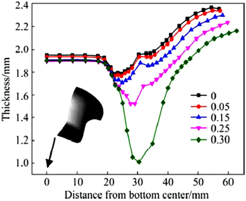
Thickness distribution for various friction coefficient (µ) under condition 1. 16
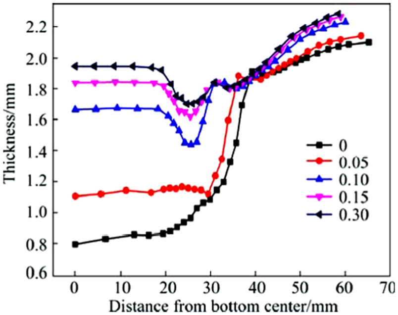
Thickness distribution for various friction coefficient (µ) under condition 2. 16
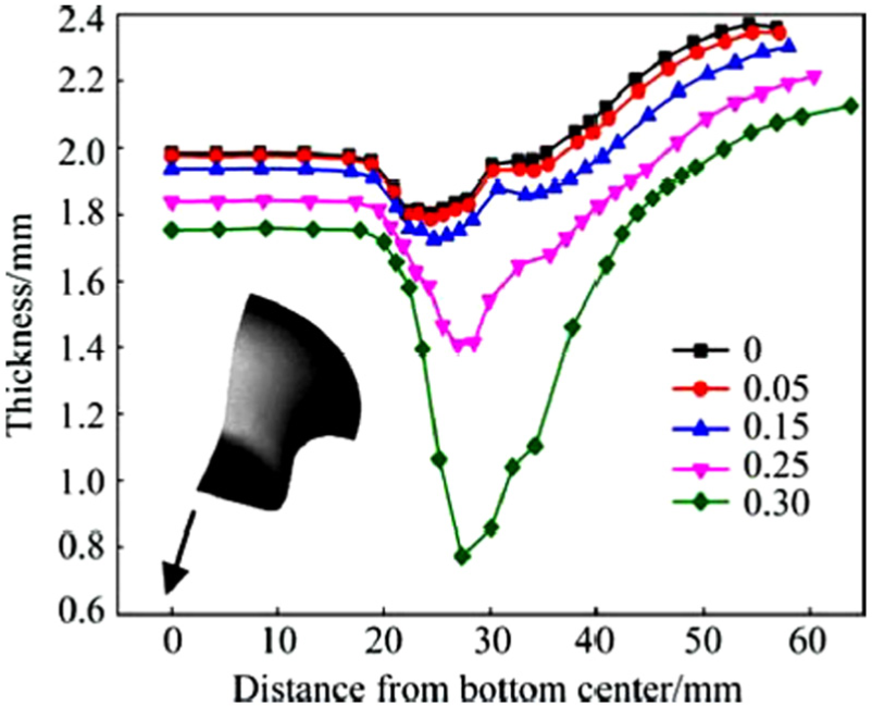
Thickness distribution for various friction coefficient (µ) under condition 3. 16
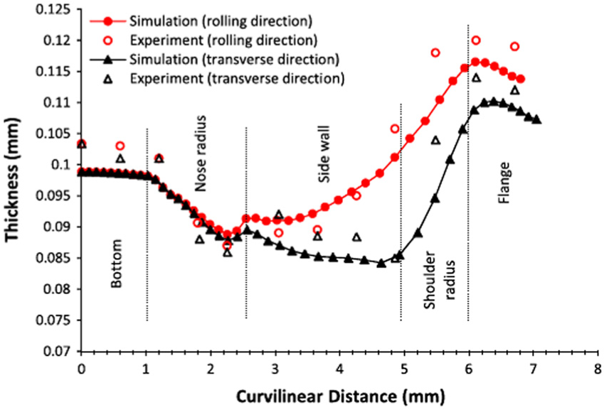
The effects of surface texturing, electro-discharge texturing and mill finish on friction behaviour were analysed by Ju et al. 17 while stamping of Al 5182-O aluminium sheet using cup drawing test. The numerical simulation was performed for different lubrication conditions to determine the coefficient of friction at the tool and work piece (blank). The thickness distribution was measured along with the rolling and transverse directions (see Figure 9(a) and (b)), and it was found that the dry film lubrication with a coefficient of friction 0.08 shows better lubricity than wet lubricants with a coefficient of friction 0.12.
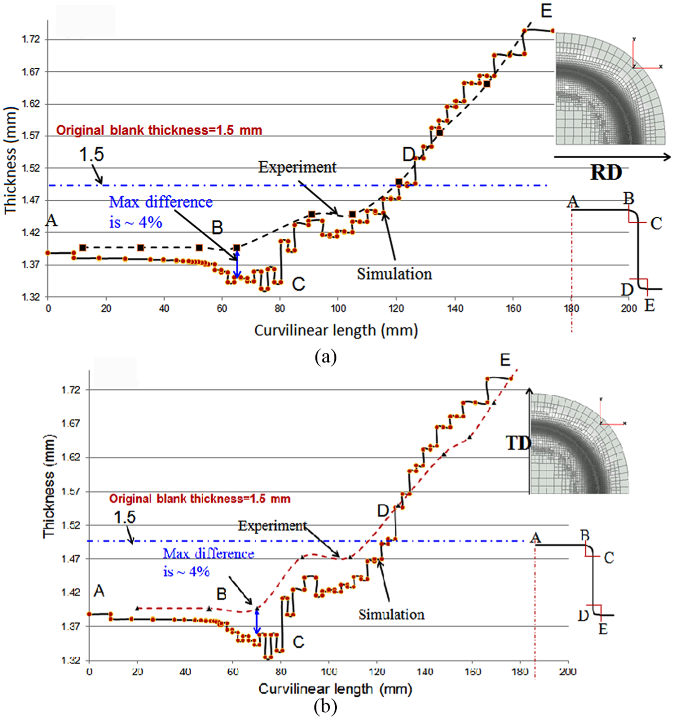
Comparison of thickness obtained from experimental and simulation results for lubrication F: (a) rolling direction and (b) transverse direction. 17
Yang 18 proposed a lubrication/friction model with a combination of elastic–plastic FEM code for axisymmetric deep drawing process for prediction of friction coefficient, contact area ratio and strain distribution. The effect of surface roughness on lubrication flow was included using Wilson and Marsault’s average Reynolds equation where the calculated friction was expressed in terms of lubricant viscosity, sliding speed, lubricant film thickness, strain rate and sheet roughness. Also, Zhang et al. 19 analysed the drawing behaviour and drawing ability of AZ31 alloy sheets with the different initial texture. It was observed that compared to as-received sheets, the repeated unidirectional bending processed sheets were drawn successfully with LDR of 1.7 but found weaker texture intensity at the shoulder which contributes to sheet thinning.
Thinning in different metals
The deep drawing process tooling is designed by considering the factor such as material behaviour. It has a significant effect on designing geometrical parameters and LDR. It was observed that proper selection of material plays a significant role in the successful deep drawing of a component. Gao et al. 20 investigated the influence of material parameters such as yield stress, hardening exponent and elastic modulus on deep drawing of a thin-walled hemispheric surface part by developing a three-dimensional FE model. It was observed that the effect of hardening exponent, yield stress, equivalent strain and punch force had more influence on thickness variation. The materials with high formability such as aluminium alloy and steel alloys can be preferred for deep drawing processes. Also, the zero-defect manufacturing process was introduced by Zoesch et al. 21 for the detection of cracks and thinning of material in the deep drawing process. The 3MA (micro-magnetic, multi-parametric, microstructure and stress analysis) is a non-destructive testing which was used to investigate the characteristics of ferromagnetic materials qualitatively and quantitatively. The obtained result from proposed method shows the direct correlation with sheet thickness variation.
Aluminium metal sheets
The effect of parameters such as forming rate, temperature and friction between a blank-tooling element and blank holder pressure (BHP) on formability of aluminium alloys in warm deep drawing was investigated by Kim et al. 22 The thickness variation was maintained by applying large temperature gradient between the die and punch. It was observed that LDR was decreased when blank and tooling were heated to the same temperature, whereas the warm deep drawing of magnesium AZ31 alloy sheet was carried out by El-Morsy and Manabe 23 using finite element analysis (FEA) tool. The heat transfer effect was considered for improvement of drawability and temperature distribution which helps in drawing a blank without thinning. It was observed that with an increase in punch speed, the cup height and heat transfer decrease, whereas temperature at the punch bottom increases. Also, Zheng et al. 24 proposed an approach combined with FEM to analyse the deep drawing of magnesium alloy AZ31 cylindrical cups under non-isothermal condition. It was observed that the applied approach works efficiently to predict a fracture at punch nose radius and die shoulder radius at different elevated temperature.
Ren et al.25,26 carried out warm deep drawing of magnesium alloy AZ31 square-shaped cup using numerical and experimental techniques. The thinning observed at the corner of square-shaped cup can be reduced by applying specific punch speed and temperature. The punching speed of 6 and 120 mm/min was maintained for forming a sound cups at 150 °C and 250 °C. Also, the correlation between material properties obtained from tensile test and process parameters such as forming temperature, punch speed and geometrical shape of blank was proposed. It was observed that with an increase in temperature, the elongation increases and work-hardening decreases, whereas the material thinning and punch force can be decreased using C-shaped blank.
The FLD generation, discrete element (DE) and FE coupling simulation were carried out by Dong et al. 27 by applying visual basic language to predict the fracture instability and strain distribution in AA7075-T6 (aluminium alloy cold-rolling sheet) conical cup. At forming temperature of 250 °C, the conical cup with half cone angle of 15° and the relative height of 0.57 was formed in a single stroke. In contrast, Raju et al. 28 used Taguchi’s signal-to-noise ratio for deep drawing of AA 6061 sheet. It was observed that the die shoulder radius has more influence on thickness variation than BHF and punch nose radius. The variation in thickness causes stress concentration which leads to failure of a component.
Steel metal sheets
Bandyopadhyay et al. 29 carried out laboratory-scale deep drawing test to study LDR of tailor-welded blanks (TWB) having a combination of dual-phase steel and interstitial-free (IF) steel. The simulation was carried out by developing an FE model and further incorporating a theoretical model of FLD to predict thinning effect and failure location of the component. However, the transverse tensile testing of TWB and laser-welded blank of low-carbon steel was carried out by Vasudevan et al. 30 to investigate the effect of anisotropy in terms of thickness variation for different forming depth and location. It was observed that the factors such as R value and Lankford anisotropy parameter influences thickness distribution and failure location in case of TWBs. The drawing depth for laser-welded blank was observed to be decreased by 5%–7% compared to parent metal due to the influence of narrow weld zone of 0.5–0.7 mm.
Serri and Cherkaoui 31 implemented Abaqus explicit FE code using VUMAT subroutine to investigate the effect of martensitic phase transformation on formability of transformation-induced plasticity (TRIP) steel sheets. The effect of stress state and kinetics of martensite phase transformation on a deep drawing of a cup was investigated at a different temperature.
Chen et al. 32 proposed two models, one with the effect of strain path and other with the effect of both size and strain path for the prediction of forming limit of stainless steel 304 foils at the micro-scale level. It was found that the ultimate tensile strength and yield strength increase with the increase in thickness to average grain size ratios (T/D), whereas the fracture strain also increases with increase in T/D except for 20 µm thickness. The effect of strain path was also studied by Thuillier et al. 33 on two-stage reverse deep drawing of mild steel cylindrical cups with the thickness of 0.98 mm where the hardening models were used for the calculation of cup thickness for different orientations in rolling direction.
The numerical simulation was carried out by Ethiraj and Senthil Kumar 34 for deep drawing of austenitic stainless steel 304 circular cup to improve LDR at higher temperatures. It was observed that LDR for 1-mm-thick sheet at room temperature was 2.1, whereas for 1500 °C, it was 2.5. The variation in results obtained from experimental and numerical simulation was about 5%.
Coated metal sheets
The metal sheets are coated with other metal to enhance the forming property. Zhou et al. 35 developed an elastic–plastic FEM for a multi-stage deep drawing of nickel-coated steel. The thickness variation was influenced by principal stresses, and deformation in the coating was observed at the flange and dies fillet profile. Also, Lim et al. 36 performed numerical analysis for the prediction of formability of vinyl-coated metal (VCM) using Gurson–Tvergaard–Needleman (GTN) damage model. The formability of VCM material was evaluated by generation of forming limit curve (FLC) through dome test simulation using Nakazima specimen. From the analysis, it was identified that the adhesive layer damage was influenced by die fillets and punch velocity. On the contrary, Mamalis et al. 37 used explicit nonlinear FE code DYNA3D for the simulation of deep drawing of square section–coated sheets. The simulation helps in the prediction of material flow and load curve for macroscopic point of view in order to avoid thinning of the cup. Also, the weldability, formability and surface micro crack were analysed for hot deep drawing by Lee et al. 38 using laser-welded blank of Al-Si- or Zn-coated boron steel of different thicknesses. The hardness observed in welded area of Zn-coated boron steel was 450 HV, but peeled off at 950 °C.
Other metal sheets
The blank holder made up of concentric rings was used by Brabie et al. 39 for minimizing the sheet thickness variation in deep drawing of copper alloy cylindrical parts. The thickness measured along the meridian contour had a maximum value at the top edge of the cup and minimum value at the bottom part. The thickness variation is observed for cup with a diameter of 2 and 20 mm (see Table 4 and Figure 10). The proposed solution minimizes the sheet thickness variation by proper utilization of BHF, contact force and friction force. In contrast, Zhang et al. 40 developed a texture and microstructure for cold deep drawn pure titanium. It was found that the recrystallization texture decreases due to increase in twinning and dislocation slip increases by over drawing which results in strengthening the texture.
Comparison of thickness variation in cup with initial thickness of blank. 39
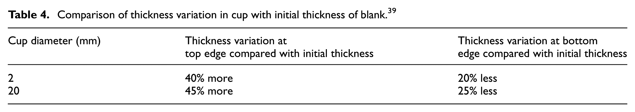
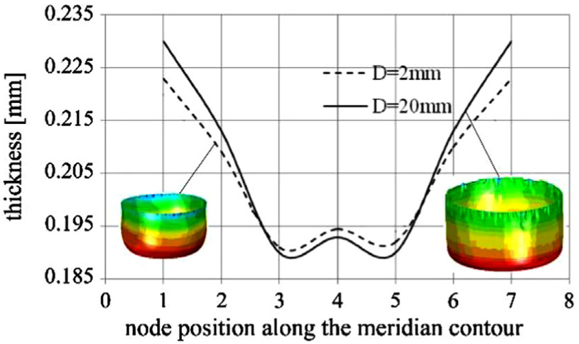
Thickness variation obtained for initial tool geometry along the meridian contour. 39
Multilayer metal sheets
The multilayer metal sheets are manufactured by arranging different layers of different materials in order to achieve desirable properties. The requirement of component design with manufacturing conditions can be satisfied by proper selection of a combination of materials and processes. 41 The aluminium alloys are the most common metal found in the literature of deep drawing process for multilayer sheet because of its high formability property and lightweight. Ghosh et al. 42 investigated the effect of drawing ratio, holding time, effect of ram speed and temperature on warm deep drawing of Al–Mg–Si alloys (EN AW-6016 and EN AW-6061) from room temperature to 250 °C. No change was observed in anisotropy by change in temperature, whereas change in thickness was observed from bottom to the top with minimum at mid-height of the wall. Also, Li et al. 43 investigated the interface microstructure, deformation behaviour and formability of composite (Al(5052)/Mg(AZ31)/Al(5052)) which was fabricated by the accumulative roll-bonding process at high temperature. The optimization of parameters such as punch speed, punch temperature and dies curvature radius was carried out to maximize the LDR (see Figure 11). The drawing ratio of 3.1 was obtained for 200 °C and keeps increasing with forming temperature (see Figure 12). The drawing of Al/Mg/Al multilayer composite sheet at a temperature of 200 °C had fewer tendencies of thinning than 150 °C.
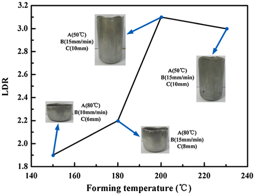
Effect of deep drawing parameters on LDR at different temperatures for composite material (Al(5052)/Mg(AZ31)/Al(5052)). 43 A, B and C are punch temperature, punch speed and die curvature radius.
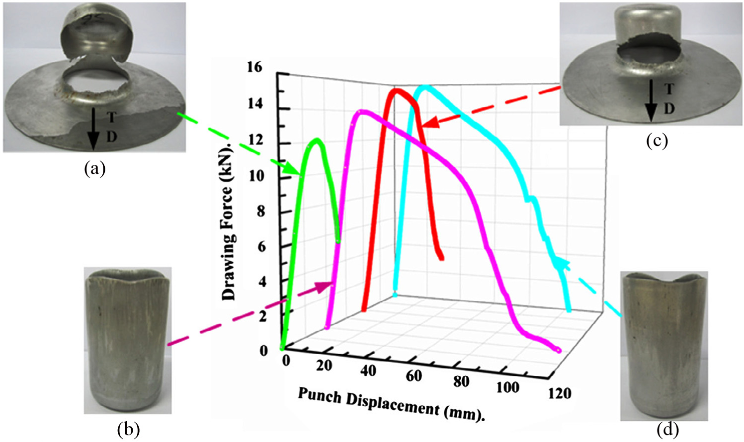
Effect of punch force on displacement of multilayer composite sheets (Al/Mg/Al) drawn at different condition with respect to punch speed (A), die curvature radius (B) and punch temperature (C). 43 (a) Fracture – die at 230 °C, DR= 3.0., A(80)/B(15)/C(10), (b) Success – die at 230 °C, DR = 3.0., A(50)/B(15)/C(10), (c) Fracture – die at 200 °C, DR= 3.2., A(50)/B(15)/C(10) and (d) Success – die at 200 °C, DR= 3.1., A(50)/B(15)/C(10).
The theoretical, experimental and numerical analysis was carried out by Bagherzadeh et al. 44 to investigate the behaviour of laminated aluminium/steel bimetallic sheets using Fortran based code. The code was used for the model of non-uniform oil pressure distribution in the hydromechanical deep drawing process. The wider working zone can be achieved by reducing drawing ratio and thickness of the sheet. 45 It was observed that material parameters such as process window, formability of aluminium sheet, layer thickness, and lay-up arrangement influence the forming condition. The effect of lay-up on process window prediction (see Figure 13) and higher LDR with lower thinning for the low formable aluminium sheet was achieved in the case of A/S lay-up than S/A lay-up (see Figure 14).
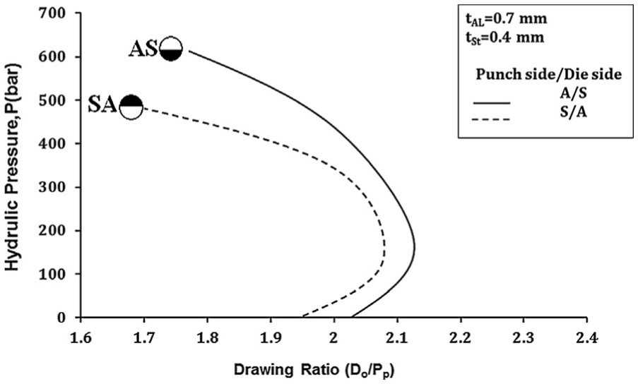
Effect of lay-up predicted by FE simulation on process window. 45
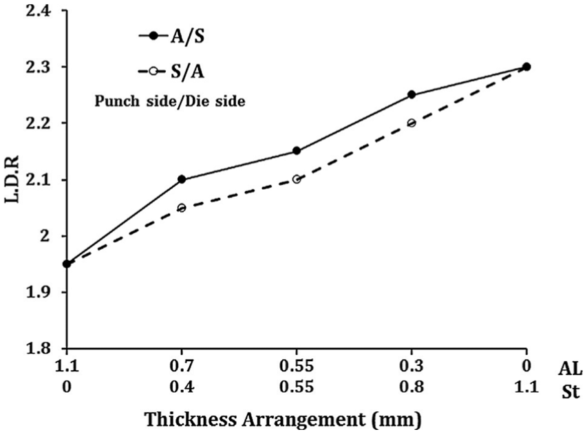
Predicted LDR for various lay-ups and thickness combinations. 45
Thinning in composite material
Nowadays, the composite materials are used on large scale especially in automotive industries due to their property of high strength and lightweight. They are manufactured using different techniques having different chemical and physical properties.
Woven composites sheets
Machado et al. 46 analysed forming of woven-reinforced thermoplastic matrix composites by introducing temperature- and rate-dependent material model to identify the thermomechanical shear behaviour. At low forming speed, the higher shear angle was induced due to lower stiffness of the material. The drop in temperature was observed which resulted in an increase in shear stiffness. Also, a new failure criterion was proposed by Wang et al. 47 based on strain and strain ratio for woven natural fibre composite. The study focuses on the effect of water treatment on pre-consolidated natural fibre composites and generation of FLC for different conditions. The generated FLC incorporates with FEA simulation. It was observed that proposed failure criteria predict failure depth and failure region in stretch forming.
Epoxy filament composite sheets
Lee et al. 48 investigated the effect of process parameters such as blank holding force and punch velocity on formability of CR340/CFRP composites on deep drawing process. The obtained depth for CR340/CFRPR*, a composite with required thickness, was higher than CR340/CFRP composites when blank holding force of 15 kN was applied (see Figure 15(a) and (b)). As the blank holding force increased from 30 to 90 kN, a constant forming depth was obtained for CR340/CFRP and CR340/CFRPR* composites. In contrast, Kim et al. 49 fabricated an interpretation model of E-glass/epoxy filament wound composite pressure vessel using deep drawing and ironing process. It was observed that the process planning drawings could be generated automatically using process design module and punch load which was minimized by regulating the distance between dies.
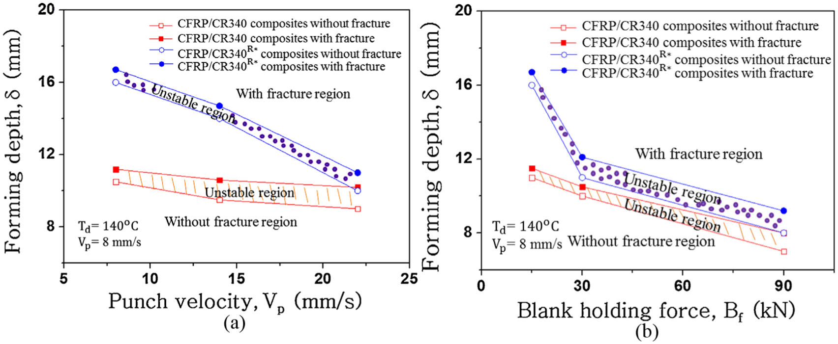
Variation in forming depth due to (a) blank holding force (Bf) with Td = 140 °C and Vp = 8 mm/s and (b) punch velocity (Vp) with Td = 140 °C and Bf = 15 kN. 48
Knitted fibre composite sheets
Lim et al. 50 carried out the optimization for formability of knitted fabric–reinforced polypropylene composite sheet by introducing parameter X which describes the amount of stretching relative to drawing. The effects of a parameter such as blank size, blank holding load and tool geometry on formability of composite material were analysed in terms of thickness variation. It was found that knitted fabric composite is a better material due to fabric reinforcement that facilitates distribution of strain and ease of loop straightening that caters for blank stretching. Furthermore, the investigation was carried out on knitted fabric–reinforced thermoplastic composite sheets to exhibit excellent stretching and drape ability. 51 Whereas the nonlinear computational algorithm was used by Takano et al. 52 for simulation of deep drawing of knitted fibre–reinforced thermoplastic composite material to determine the deformation and behaviour of the composite material by adopting homogenization theory.
Reinforced composite sheets
The FLC for flax fibre–reinforced polypropylene composite along with maximum strain failure criterion was proposed by Wang et al. 53 The FEA analysis was carried out to draw the samples and predict the failure in natural fibre composite by plotting FLD in different forming deformation modes. On the contrary, Jiang et al. 54 investigated the formability of particle-reinforced metal matrix composite (MMC) by performing tensile and compressive tests at room temperature. It was observed that by imposing a combination of superimposed hydrostatic pressure and heat treatment, an accurate deep drawing of MMC sheet can be carried out without failure due to thickness variation. Also, an anisotropic elastoplastic constitutive model was developed by Dean et al. 55 for short fibre-reinforced polymers (SFRPs) for clinching joints which help to provide a realistic numerical prediction and to investigate mechanical response of joints in practical applications.
Sandwich composite sheets
The study was carried out by Sokolova et al. 56 to identify the formability of 316L/PP–PE/316L sandwich composites in deep drawing process for different sample size and core thickness. The two flat punches with different shape and size were analysed using photogrammetric and metallographic techniques. It was observed that the sandwich composite was influenced more by core thickness and geometry of punch. The study on deep drawing and bending behaviour of metal–polymer–metal sandwich composites was carried out by Sokolova et al. 57 with embedded different solid and mesh steel inlays. The thickness of composites was quantified by photogrammetry. The observed thickness was more for the sandwich with mesh inlays than sandwich with circular solid inlays.
Other composite sheets
The failure analysis of cylindrical cup drawing was carried out by Park and Colton 58 using rapid prototype tooling made up of polymer composite material. The failure mode was determined using stress–strain response obtained from FEA and validated by performing experiment tests. The parametric study was carried out and valid damage parameters were identified for die failure modes based on failure mechanism. However, Hankeln and Mahnken 59 developed a mesoscopic model for deep drawing of carbon fibre prepregs by splitting constitutive equation for materials as anisotropic elastic, isotropic, visco-elastic behaviour which was able to represent a definite behaviour of the material in terms of thickness variation and strains. Also, both the intragranular dislocation phenomenon and behaviour of fine-grained alumina–zirconia ceramic composite were investigated by Chen et al. 60 for deep drawing process. It was observed that the Al2O3/ZrO2 can be elongated to dome height of 12 mm with punching rate of 0.6 mm/min at a temperature of 1400 °C.
Advanced deep drawing techniques
Recently, a lot of works is been carried out in the field of engineering to manufacture a component with a compact shape and complex profile. For the manufacturing of such components with different materials, different techniques such as micro deep drawing and hydro deep drawing are required.
Micro deep drawing technique
The micro deep drawing process had investigated by few authors for single metal sheet as well as for multilayer sheets. Irthiea et al. 61 carried out a micro deep drawing of stainless steel 304 sheets by performing the experimental and numerical simulation. The Abaqus codes were used in the numerical simulation for prediction of quality and aspect ratio of micro metallic cups. This study focuses on the investigation of forming parameters such as sheet thickness, friction conditions at contact, initial gaps and anisotropy of SS 304 material (see Figures 16 and 17). The optimization of the initial gap with respect to sheet thickness, thickness distribution, and punch/stroke relationship was also studied (see Figures 18 and 19). It was observed that the drawing of stainless steel 304 cups with larger aspect ratio can be carried out using flexible die through single micro deep drawing stage which was impossible by a conventional method. In contrast, Manabe et al. 62 carried out FE simulation to validate the surface roughness model in a micro deep drawing of the cup with a diameter of 500 µm by developing a high-precision sequence blanking and micro drawing setup. The thinning effect was observed at the wall and corner of cup, whereas thickening effect was observed at the end part. Also, the micro deep drawing process at room temperature was carried out by Gong et al. 63 with the velocity of 0.1 mm/s using diamond-like carbon (DLC) film–coated blank holder and dies. It was observed that the DLC film helps in decreasing punch force, which results in maintaining LDR and thickness.
Thickness distributions along rolling and transverse directions. 61
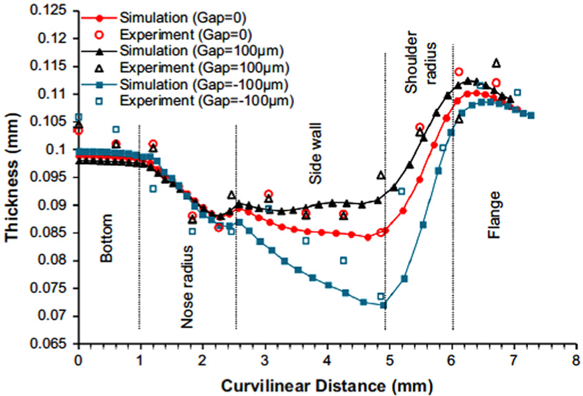
Thickness distributions along transverse direction for different initial gaps. 61

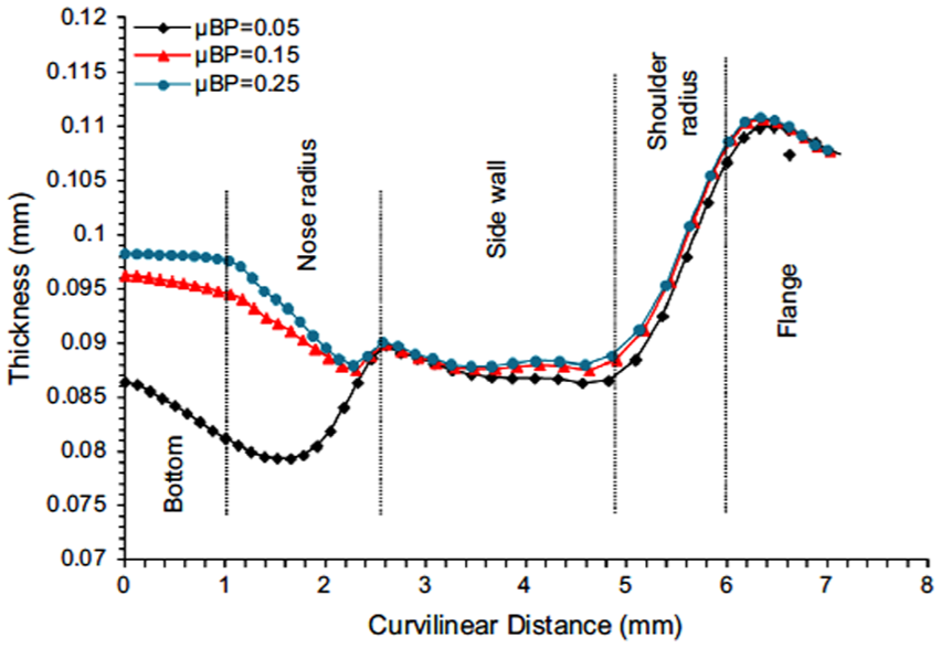
Thickness distributions along transverse direction for friction coefficients at blank/holder interface. 61
Thickness distributions along transverse direction for friction coefficients at blank/punch interface. 61
Shimizu et al. 64 studied the thickness strain evolution and plastic anisotropic behaviour in a micro deep drawing of ultra-thin rolled phosphor bronze foil with the thickness of 20–300 µm. The experimental tests were performed to show the importance of geometrical anisotropy, such as defects and orientation of surface topography for unstable deformation of ultra-thin rolled metal foils. The opposite behaviour was observed in a case of 100- to 300-µm-thick sheet and 20- to 50-µm-thick foils for the in-plane anisotropy of elongation. Also, the Fu et al. 65 investigated the effect of grain size, die design and deformation process on micro blanking and deep drawing of copper sheet. The numerical simulation was carried out to analyse the material thinning and deformation load. It was observed that the deformation load decreases with the increase in grain size. This decrease in deformation load was not significant when there were only a few grains in the cross section of the sheet metal.
Hydro deep drawing technique
In the last decade, a lot of advanced techniques have been developed in deep drawing process using hydraulic power. The hydro deep drawing technique can be used for drawing a single- and multilayer sheet effectively by maintaining the dimensional accuracy and reducing defects like scratching and thinning. A modified hydrodynamic deep drawing method was proposed by Wang et al., 66 which was assisted by radial pressure with the inward liquid flow where the effect of radial pressure on wall thickness distribution, punch force and compressive stress in blank flange was investigated by performing a numerical simulation. The uniform wall thickness can be achieved if the pressure in the die cavity reaches the maximum value when a punch displacement equals the punch corner radius plus die entrance radius. However, the numerical simulation and experiments were carried out by Lang et al. 67 to investigate the hydro forming characteristics such as thickness distribution, process window, drawing ratio and quality by applying uniform pressure. It was observed that the drawing ratio of 3.11 can be achieved for material Al1050-H0 and 2.46 for material Al6016-T4 which was possible using optimized radial pressure. Also, the Hashemi et al. 68 carried out hydrodynamic deep drawing process assisted by radial pressure to obtain a process window diagram for Al1050, pure copper and DIN 1623 St14 steel which was used for prediction of appropriate forming area and rupture or wrinkling occurrence under different loading pressure paths. The numerical analysis was carried out by considering process parameters such as blank material, pressure path and thickness. It was observed that the sheet with less thickness and higher strength had better formability with uniform thickness distribution in the final product. The theoretical model was proposed by Jalil et al. 69 to investigate the critical rupture pressure in forming of an Al1050/St13 double-layered part using hydrodynamic deep drawing process. It was observed that the thickness of each layer increases from 0.3 to 0.7 mm, which results in an increase in safe pressure range from 30 to 55 MPa to 137−300 MPa.
The theoretical and experimental approach was used by Fazli and Dariani70,71 to achieve a working zone for the bulging and axisymmetric hydromechanical deep drawing process. It was observed that the geometrical parameters, material properties and tooling conditions had more influence on fluid pressure (see Table 5), whereas the process parameters such as die profile radius, friction, chamber pressure and blank thickness influence LDR (see Table 5) which were investigated by performing FEA with experimental validation.
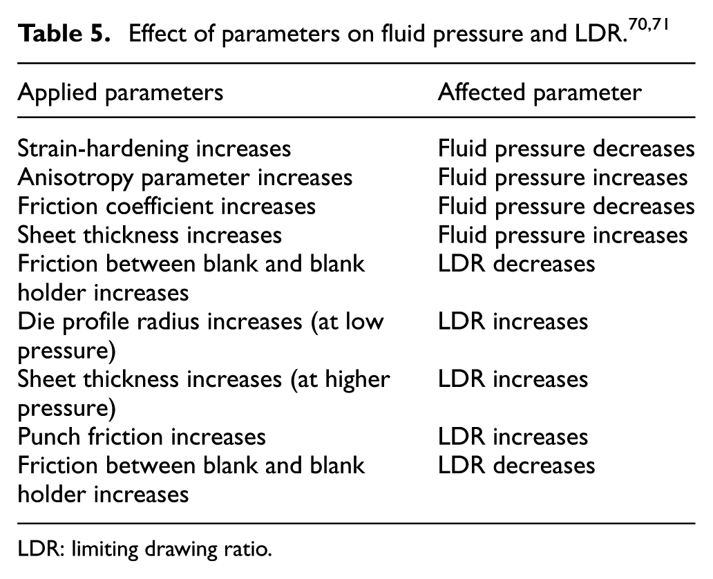
LDR: limiting drawing ratio.
Wrinkling effect
The wrinkling effect is observed when insufficient BHF is applied to hold a blank while performing deep drawing operation. A lot of attempts were made by authors to avoid wrinkling defect by introducing different drawing techniques. The techniques such as different blank holder shape, the size of blank holders, and variable blank holding force (VBHF) were used to predict wrinkle formation at the flange region.
Approach to predict wrinkling effect
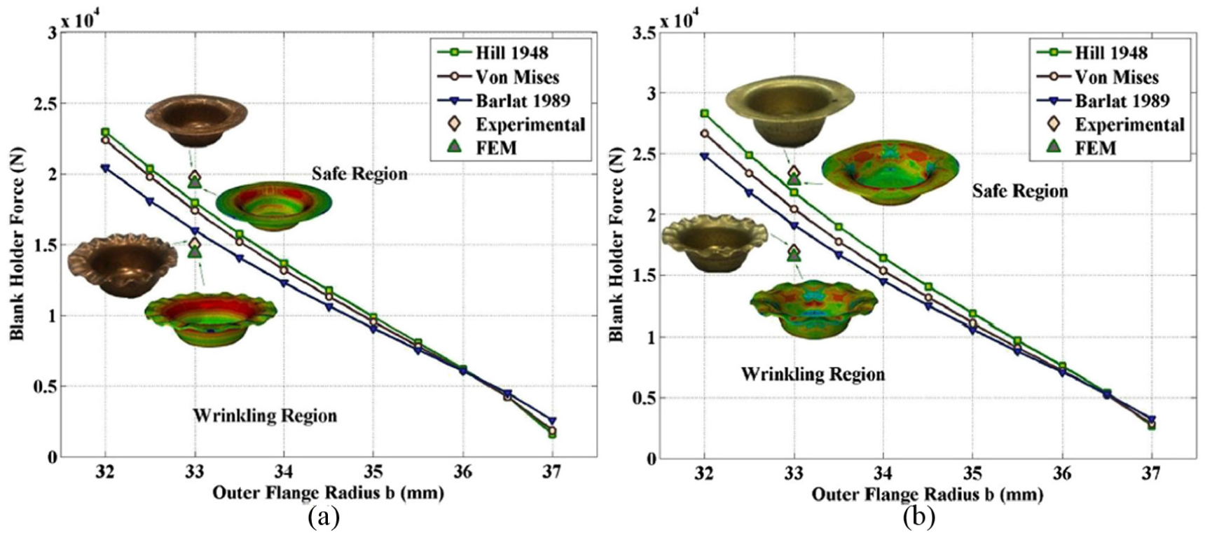
Traditionally, the wrinkles generated at the flange region of the cup were predicted using analytical models and validated by performing experimental tests. Kadkhodayan and Moayyedian 72 used two-dimensional plane stress wrinkling model and bifurcation function from Hill’s general theory to investigate the elastic–plastic flange wrinkling of a circular blank for deep drawing process. In contrast, Chu and Xu 73 analysed the onset flange wrinkling in deep drawing of the cup by considering it as an elastoplastic bifurcation problem. It was observed that the parameters such as drawing ratio, material properties, strain hardening and flange width influence wrinkle effect. Also, Shafaat et al. 74 carried out a study on onset wrinkling by developing deflection function for deep drawing of the conical cup using Hill’48 and Hosford yield criteria under isotropy, planar anisotropy and normal anisotropy conditions. It was observed that better prediction can be achieved using Hosford yield criterion, whereas the accuracy of prediction of results can be increased by increasing effective stress. Also, the accuracy of results was increased by implementation of analytical models with mathematical models. The implementation of mathematical models reduces time and cost which were spent on performing experimental tests. Kim et al. 75 investigated the initiation and growth of wrinkling in deep drawing of an elliptical cup using bifurcation theory and FEA with continuum-based resultant shell elements. The FE formulation was based on incremental deformation theory and elastic–plastic material modeling. On the contrary, Saxena and Dixit 76 used Hill’s bifurcation criterion for the prediction of flange wrinkling in deep drawing of the circular and square cup. The geometrical parameters, process parameters, and material were considered for optimization of deep drawing of cup without wrinkling which was predicted by using Lagrangian approach. Also, Anarestani et al. 77 carried out a study on the critical blank holding force for deep drawing of cylindrical component and wrinkle formation at flange region for different materials like ST12, ST14, copper and brass (see Figures 20 and 21).
Effect of yield function on wrinkling limit curve: (a) ST12 and (b) ST14. 77
Effect of yield function on wrinkling limit curve: (a) copper and (b) brass. 77
The obtained analytical results using Hill’s bifurcation method reveal that ST12 had highest compressive instability, whereas copper plate had lowest compressive instability. The theoretical and experimental approach was combined by Magrinho et al. 78 to determine the wrinkling and formability limits in sheet metal forming. The numerical simulation was used to carry out cylindrical deep drawing without a use of blank holder. It was observed that the loading path beyond transition point will give rise to wrinkling effect. In contrast, Zeng and Mahdavian 79 developed a theoretical model to predict a number of waves formed and critical conditions in wrinkling while performing a deep drawing operation at room temperature and at elevated temperature. The equilibrium of moments was applied on segments of the wrinkled flange, and critical conditions were analysed with and without the blank holder.
Kawka et al. 80 carried out static explicit ITAS3D and dynamic explicit simulation to simulate wrinkling in conical cups. It was observed that the obtained numerical results were influenced more by the initial shape of FE mesh. Also, De Magalhaes Correia and colleagues81–83 performed FEA for prediction of wrinkling effect in deep drawing of the conical cup using Abaqus/Explicit code. The wrinkling limit curves depend on material properties, whereas local geometry was defined by developing a local analysis. The plastic yielding was used as a criterion for transversely anisotropic material, and onset wrinkling was analysed as elastic–plastic bifurcation for thin shallow shells. It was observed that the critical wrinkling was affected by anisotropy on the stress state and sheet curvature. Also, the bifurcation analysis was performed to generate a wrinkling limit curve for different orientations of orthotropic axes with respect to principal stress axes and geometrical axis of the principal curve.
A review was conducted by Mistri et al. 84 on experimental and numerical techniques used in the deep drawing process. The detailed content of geometrical parameters such as punch radius, die radius, radial clearance, blank thickness and physical parameters which include coefficient of friction, blank holding force and cracking load was discussed. However, these deterministic efforts neglect the brief study of defects such as thinning, wrinkling and spring-back. The advance trends in the industry are deep drawing of multilayer and composite materials which were neglected in the study.
Effect of parameters on wrinkling
The precise deep drawing process can be achieved by optimizing the process parameters. Dwivedi and Agnihotri 85 carried out a numerical simulation to optimize the design process for deep drawing of aluminium and brass cups by considering the effect of die-punch geometry, punch-die-to-fillet radius, LDR and drawing load with respect to punch stroke.
The optimization of design for wrinkling and thinning was carried out by Shivpuri and Zhang 86 for varying friction constraints and predefined blank holding force. The optimum design was identified by a deterministic Pareto front for multiple design alternatives and trade-off strategy which was determined using FEA-based algorithm approach (non-dominated sorting genetic algorithm-II (NSGA-II)). The deterministic optimized design had shown 33% improvement than uniform friction design. Agrawal et al. 87 carried out optimization of process parameters such as blank holding pressure, and wrinkle formation was determined in flange region during deep drawing of the axisymmetric cup. The upper bond analysis was performed for estimation of thickness variation, whereas minimum blank holding pressure was applied to suppress the wrinkle formation. The influence of process parameters such as punch velocity, BHF and blank temperature on the hot deep drawing of thin boron steel sheet was investigated by Lee et al. 88 The temperature of 300 °C was maintained for punch and dies to improve the formability. The change was observed for different parameters (see Table 6).
Effect of change in process parameter. 88
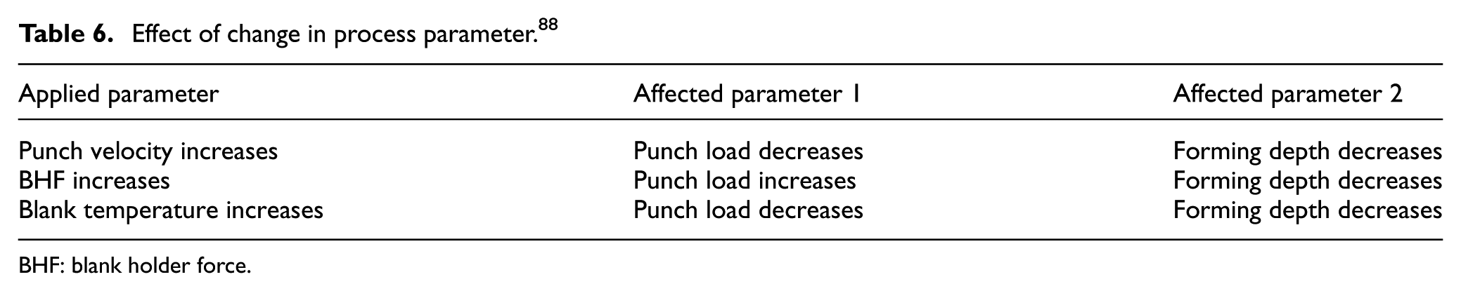
BHF: blank holder force.
The review on optimization of process parameters using different techniques in deep drawing process was carried out by Joshi et al. 89 The parameters such as die radius, drawing speed and coefficient of friction were focused, which influence the deep drawing process and lead to the occurrence of defects such as wrinkling, tearing and scratches. The wrinkling occurred at wall and flange region of drawn cup was focused. The other defects such as spring-back and wall thinning were neglected while conducting the review.
Blank holding force
The investigation of optimum VBHF was carried out by Zhang and Shivpuri 90 for deep drawing of aluminium-killed steel conical cup. The optimization was achieved by minimizing the magnitude of fracture and wrinkling defect under process uncertainties like punch speed, sheet thickness, interface friction at die surface and punch surface. The proposed design improves yield to 99.98%, whereas traditional deterministic design improves yield to 48.04%. Also, the J-stamp simulation was carried out by Ouyang et al. 91 to investigate the effect of blank holding force in hot deep drawing of boron steel sheets by considering friction coefficient and interfacial heat transfer coefficient. It was observed that the friction coefficient between blank and punch decreases with the increase in BHF (but <30 kN); also, thickness variation and equivalent strain were significantly influenced by the increase in BHF. In contrast, Qin et al. 92 used energy method for prediction of critical blank holding force for axisymmetric deep drawing. The observed relative error for equivalent strain and circumferential stresses was 35.9% and 22.3%, respectively.
The analytical and FEA method was used by Candra et al. 93 for the prediction of maximum blank holding force over the punch stroke to eliminate cracking of cylindrical deep drawn cup. It was observed that the formability and cup depth were increased up to 8% and 17%, respectively, for the application of maximum VBHF with palm oil lubrication having a coefficient of friction 0.18 to 0.2 (see Figures 22 and 23). Also, Tommerup and Endelt 94 controlled the distribution of blank holding force using active tool system, which was integrated into existing stacked deep drawing tools without any modification in the pressure.
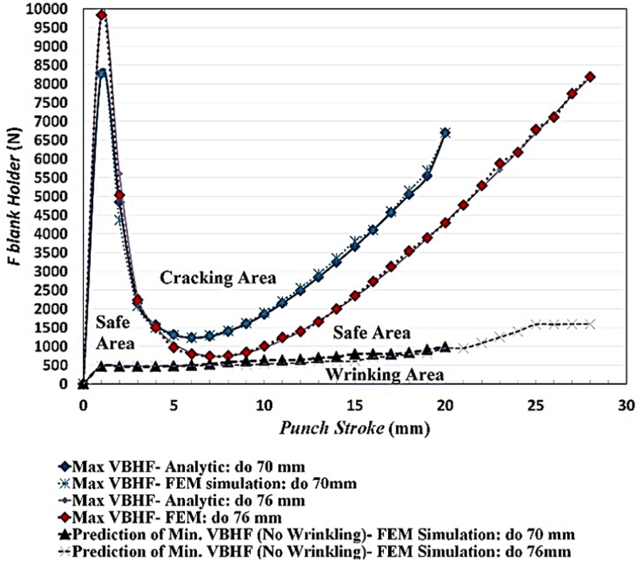
Calculation of maximum VBHF using the slab method (analytic calculation) and FEM simulation to avoid cracking for d0 = 70 mm and 76 mm; µ = 0.45. 93
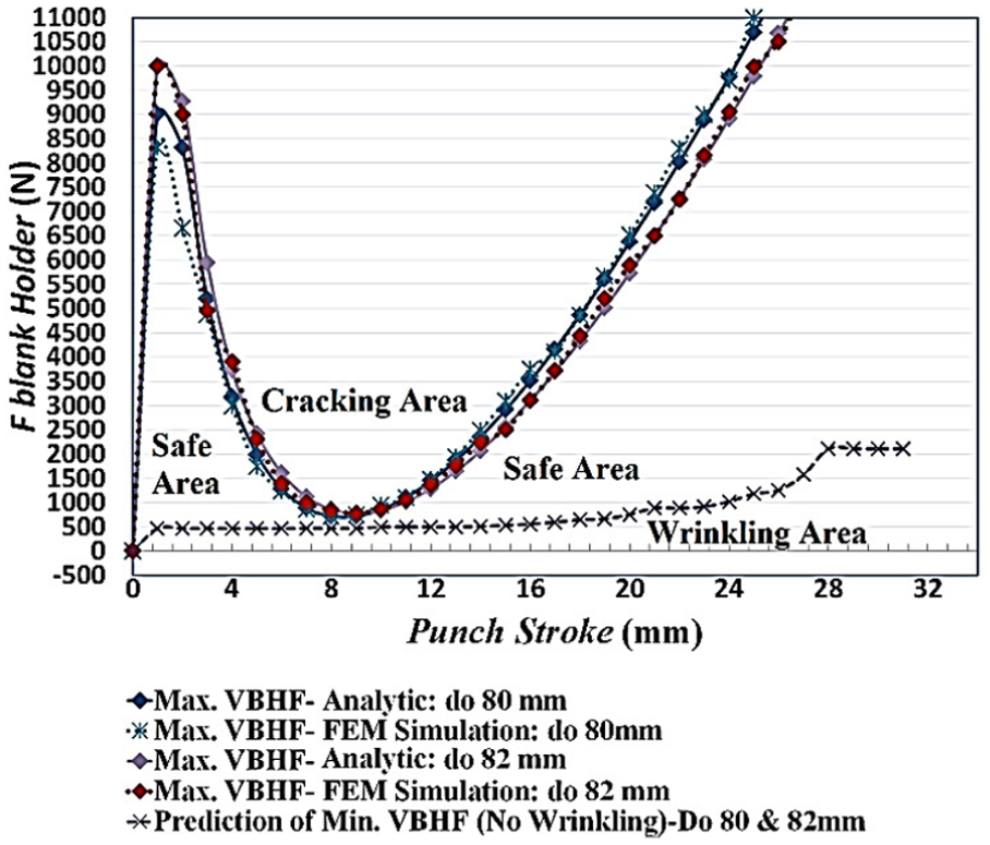
Calculation of maximum VBHF using the slab method (analytic calculation) and FEM simulation to avoid cracking for d0 = 80 mm and 82 mm; µ = 0.2. 93
The design optimization problem was constructed by Kitayama et al. 95 to identify the formability window where punch stroke was subjected to wrinkling and tearing effect. The different sample points were generated using Latin hypercube design and sequence approximate optimization which was applied with radial basis function to find the optimum VBHF and pulsating blank holding force (PBHF) using formability window (see Figure 24(a) and (b)). It was observed that constant blank holding force can be replaced with optimum PBHF for maintaining punch life while performing deep drawing process.
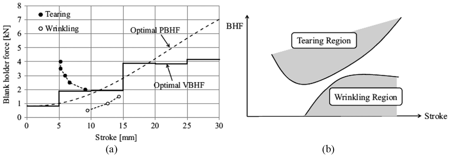
(a) Optimum VBHF and PBHF for punch stroke of 20 mm and (b) formability window of blank. 95
The review was conducted by Singh and Agnihotri 96 on research and development in a field of the deep drawing process. The obtained results from literature brief the effect of parameters such as blank shape, BHP, punch radius, die radius, the coefficient of friction and material properties on a deep drawing of the cup. The defect such as spring-back effect was not considered for review. Also, the recent techniques such as micro deep drawing, hydro deep drawing and multilayer and composite material deep drawing were also not considered.
Texture and microstructure
Tang et al. 97 investigated the deep drawing behaviour and mechanical anisotropy for AZ31 magnesium alloy sheets rolled in unidirectional (UR) and cross direction (CR). These samples were also used to investigate the properties such as tensile, microstructure and texture at room temperature. It was observed that CR sheet enhances the drawing capabilities due to improvement in ductility of 28% elongation to fracture and low r value (plastic strain ratio) close to 1, whereas UR sheets had planar anisotropy from strong basal-type texture. The different crystal material such as low-carbon aluminium–killed steel and pure titanium with a thickness of 1 mm can also be used for circular shell deep drawing. 98 Also, Tikhovskiy et al. 99 used texture component crystal plasticity FEM to predict the behaviour of aluminium alloy AA 5754 sheet for deep drawing, whereas Zheng et al. 100 used macro-textured blank holder surface based on the energy method for prediction of wrinkling at the flange region due to variation in process parameters in deep drawing process. The effect of variation in texture ratio on wrinkle formation for blank holding force of 10 kN and forming the speed of 75 mm/s was significant (see Figure 25).
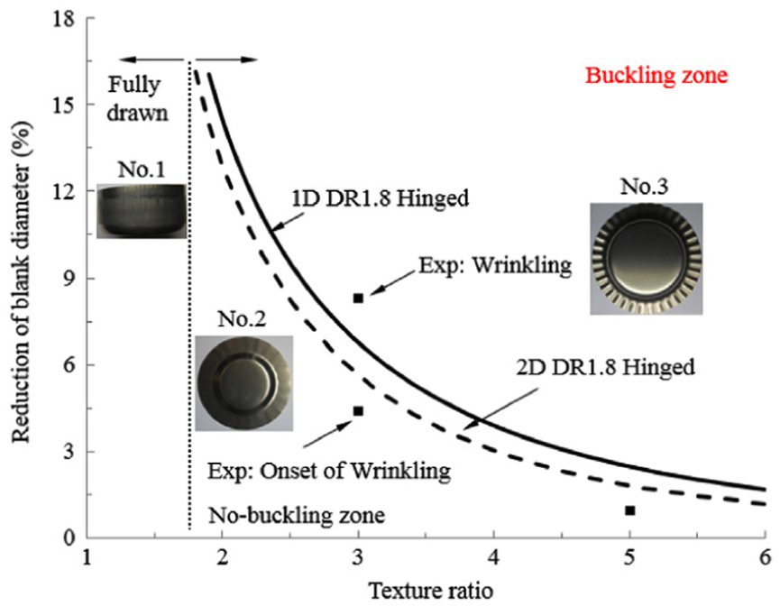
Effect of texture on wrinkling calculated using 1D analytical, 2D analytical and experimental method. 100
Wrinkling in different materials
The wrinkle formation is observed due to insufficient application of BHF to hold the blank. Similar to BHF, material properties also play a significant role in wrinkle formation. Many authors had adopted different techniques for predicting wrinkle formation in the deep drawing of different types of materials.
Aluminium and aluminium alloy sheets
Most of the authors focus their study on wrinkle formation in deep drawing of aluminium and aluminium alloys sheets. The forming characteristic is not possible to predict accurately using mathematical equations as it was stochastic and random in nature. Sivasankaran et al. 101 used ANN technique for prediction of surface wrinkling in pure aluminium sheet metals (ISS19000, ISS19600, and ISS19660) when drawn through the conical die, whereas Loganathan and Narayanasamy 102 used conical and tractrix dies for studying an effect of mechanical properties on wrinkling behaviour in three grades of annealed commercially pure aluminium sheets (ISS19000, ISS19600, and ISS19660). The wrinkling effect was observed when the plastic strain reached a critical value where strains followed nonlinear paths in wrinkling limit diagram. It was suggested that aluminium grade with a low yield stress, high strain hardening index value and high normalized hardening rate had better resistance to wrinkling. Also, Narayanasamy and Loganathan103,104 carried out a study on wrinkling of annealed different grades of commercially pure aluminium sheet metals using wrinkling limit diagram while drawing through the conical die or tractrix dies. It was observed that aluminium grade ISS19660 with a low tensile to yield ratio, high normalized hardening and high strain hardening index value had better resistance to wrinkling. The influence of friction on the prediction of wrinkle formation in deep drawing of the pre-strained circular blank to cylindrical cups through a conical die using flat bottom punch was focused.
Zhang and Shivpuri 105 presented a multi-criteria design approach to incorporate into response surface method (RSM)-based model for optimizing the probabilistic design of drawing aluminium sheet by reducing defects such as wrinkling and fracture. The RSM model was generated using FEM-based high-fidelity model, the design of experiments and simple linear weighted approach. It was observed that the quality index was improved by 42% which can be further improved to 98.97% with the reduction of friction coefficient to 2%. In contrast, Neto et al. 106 modelled material plastic anisotropy using advanced yield criterion beyond the isotropic behaviour. The FEA and experimental tests were performed for deep drawing of AA5042 aluminium alloy cylindrical cup to investigate the effect of tool geometry and process parameters on wrinkling behaviour. The predicted wrinkling shape was found to be dependent on FE mesh used for blank discretization, whereas predicted punch force was influenced by friction coefficient.
Cui et al. 107 proposed an incremental electromagnetic-assisted stamping forming method with radial magnetic pressure for deep drawing of aluminium alloy cylindrical cup. It was identified from numerical results that the forming depth was increased by 31% after consecutive coil discharge using new process over traditional process. On the contrary, Lai et al. 108 used a dual-coil electromagnetic forming system for radial Lorentz force augmented deep drawing of aluminium alloy sheet (AA1060-H24) with a large drawing ratio. The system enhances the flow of material in flange region with the increase in forming depth from 8.44 to 20.28 mm.
Copper alloy sheets
The deep drawing of the circular cup of thin copper alloy sheet was carried out by Yagami et al. 109 where the algorithm was proposed for controlling the blank holder motion in perspective of wrinkling behaviour and fracture limit. The effect of motion control on wrinkling behaviour was evaluated by performing experimental test, whereas the effect of fracture damage reduction method was evaluated by performing a numerical simulation.
Nickel-coated sheets
Wu et al. 110 carried out the FE analysis based on continuous damage mechanics by considering blank holding force for the prediction of failure modes like wrinkling in the cylindrical deep drawing of nickel-coated sheet metal, whereas developing damage mechanics and FE model 111 was used to establish a failure map for dimensionless process parameters which was divided into three regions such as wrinkling, fracture and success. The fracture in the material was observed when friction coefficient and blank holding force were large (see Figure 26(a) and (b)), whereas wrinkling was observed for small friction coefficient and blank holding force (see Figure 27(a) and (b)).
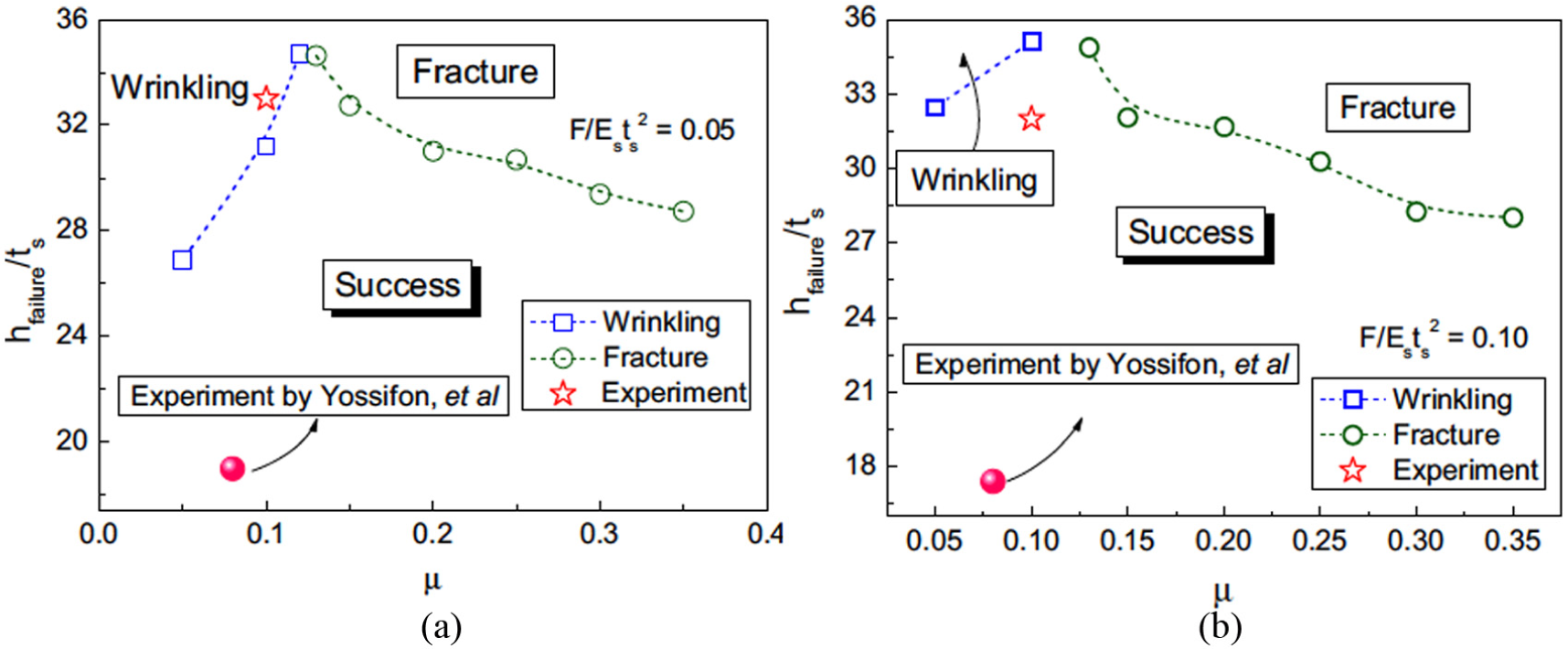
Relationship between drawing depth at failure (hfailure/ts) and friction coefficient (µ) at Q/Ests2: (a) 0.05 and (b) 0.10. 111
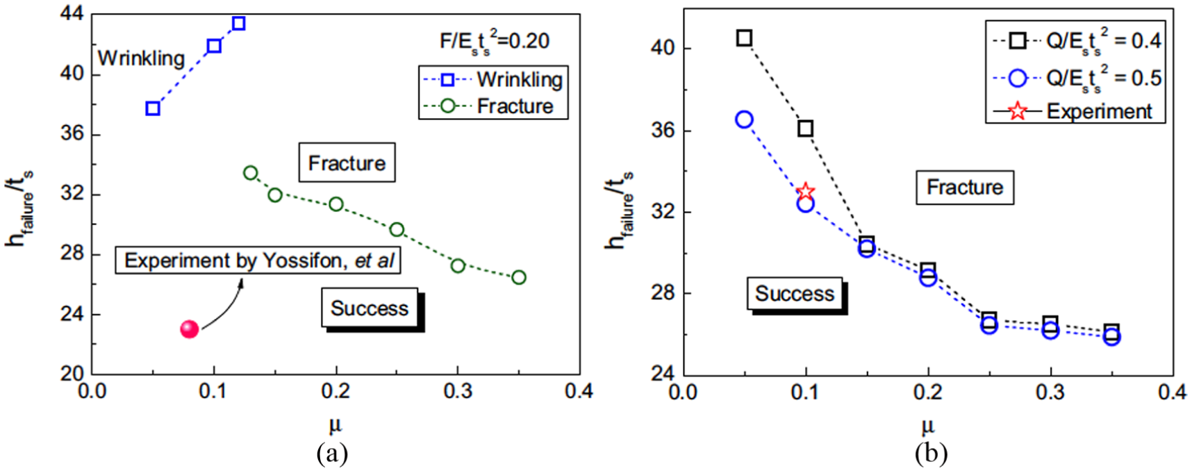
Relationship between drawing depth at failure (hfailure/ts) and friction coefficient (µ) at Q/Ests2: (a) 0.2 and (b) 0.4 and 0.5. 111
Welded blank sheets
The wrinkling behaviour analysis was performed by Abbasi et al. 112 for TWB of IF steel with a thickness of 0.8–1.2 mm by assuming principal stress direction to be deviated from principal curve axes, as a sheet is deformed in a thin segment. The wrinkle wave is initiated in a thin segment of TWB and propagates by three waves. In contrast, Wang et al. 113 analysed the welding line moment behaviour for deep drawing process of TWB sheet with different thickness using FEM technology. Also, the theoretical and experimental approach was used by Asadian-Ardakani et al. 114 to investigate the effect of non-uniform BHF on the deep drawing of a rectangular cup of tailor-welded IF steel blanks. It was observed that the weld line displacement was influenced by parameters such as thickness ratio, coefficient of friction, punch and die radius and BHF. By applying a uniform BHF results in movement of weld line towards the thicker side which can be controlled by adjustment of appropriate BHF.
Multilayer metal sheets
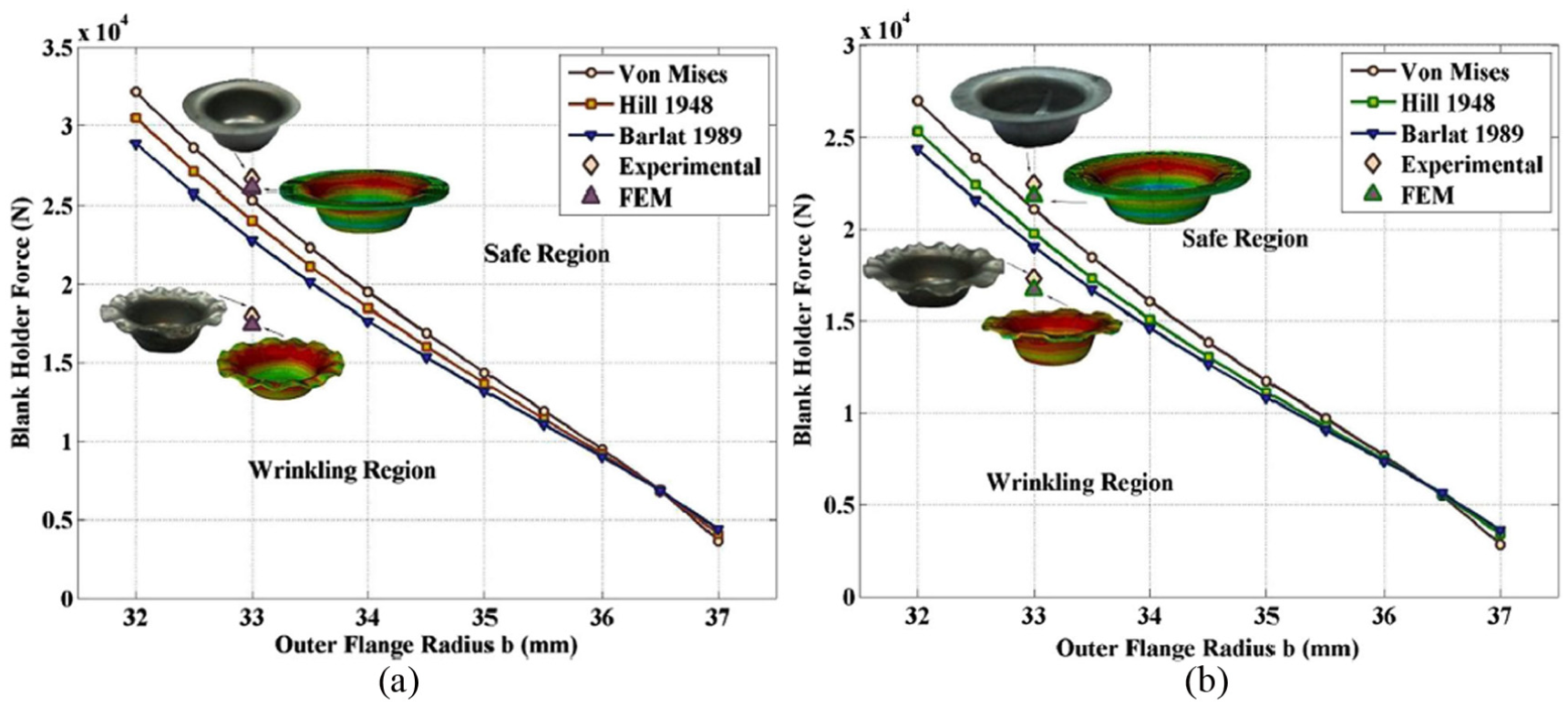
The deep drawing of aluminium stainless steel layered sheet in a circular cup was done by Morovvati et al. 115 to investigate the wrinkling effect and effect of material properties like layer, a lay-up on the blank holding force. Three different methods were used for investigating three different parameters. The analytical model based on energy method was used for wrinkle prediction, FE simulation was used for investigating the effect of forming parameters on wrinkling and experimental tests were carried out for the validation of obtained results. The same material layers (Al1050/St304) were used by Afshin and Kadkhodayan 116 for warm deep drawing to investigate the effect of the sequence layer, blank temperature and various grain sizes on thinning and wrinkling. The aluminium was replaced with brass, and numerical analysis was carried out by Atrian and Fereshteh-Saniee 117 to investigate the cause which promotes the defects such as fracture and wrinkling in deep drawing of steel/brass laminated sheets. The experiments were carried out to focus the effect of parameters such as lubrication, BHF, stacking sequence layers and diameter of composite blank on drawing process.
Composite material sheets
Cherouat and Billoet 118 investigated the elastic and visco-elastic properties of mesostructure for the pre-impregnated composite material. The two different FE families were combined which include unidirectional truss FEs representative of warp and membrane FEs representative of resin deformation for prediction of ply wrinkling and fibre orientation. On the contrary, Altmann et al. 119 carried out the study for the prediction of the strength of ply waviness in composite materials. The Puck failure criterion was used with MATLAB software to analyse the matrix-dominated effect on strength behaviour of unidirectional laminates for compressive loading. It was identified that matrix-dominated shear strength affects the failure behaviour of wavy laminates.
The prediction of forming and defects caused due to fibre displacement and inter-ply friction of multilayer carbon–weaved fabrics was done by Nezami et al. 120 by performing an analysis. The experimental tests were carried out to investigate the parameters such as carbon woven fabric, fibre integrity, and friction properties. The fabrication technology was developed by Behrens et al. 121 to reduce a wrinkle formation in deep drawing of fibre-reinforced plastic with a sheet metal. The tooling concept was suggested to maintain the pressure to avoid wrinkle formation at side wall area. The effect of inter-ply friction, co-stacking and fibre stresses in critical fibre direction on global wrinkling behaviour was investigated. The improvement in formability was observed due to the reduction in a number of different combinations of fibre angles and friction. In contrast, Zhang et al. 122 developed a shear angle curve and shear load shear angle curve using picture frame test for a thermal deep drawing of the carbon fibre woven composites. It was observed that shear load increases rapidly as shear angle exceeds 33° which results in wrinkle formation at the surface of the component. Also, Sjolander et al. 123 investigated mechanisms that are responsible for wrinkle formation in composite laminates by performing a numerical analysis. The study focuses on the effect of compression of stack and interaction between two layers with specific fibre direction on wrinkle formation.
The bias-extension tests were performed by Guzman-Maldonado et al. 124 to analyse the visco-elastic behaviour of pre-impregnated thermoplastic composites, which occurs due to in-plane shear deformation and hyperelastic behaviour of reinforcements. The wrinkling was observed due to increase in plane shear stiffness, high strain rate and low temperature. On the contrary, Rajabi et al. 125 investigated the influence of process parameters and core materials on deep drawing of thermoplastic metal composites by performing static numerical analysis and experimental tests. The experiment count was optimized by applying Taguchi method, and it was found that by maintaining a high interaction between temperature and BHF, wrinkle formation could be minimized. Also, Wang et al. 126 performed numerical analysis for deep drawing of a square box by focusing on parameters such as a position of the yarns, final shape of the laminate, the angle between a wrap and weft direction to optimize 3D weaving by developing a surface 3D weaving process.
Hydro deep drawing technique
A theoretical model based on Barlat–Lian yield criterion and tensile instability was proposed by Jalil et al. 127 to predict a critical rupture pressure in the hydrodynamic deep drawing of cone cups and validate by performing experiments. It was observed that a proposed technique with fluid pressure was applied at the peripheral edge of a cup, which helps to increase the surface finish, forming ability and dimensional accuracy. On the contrary, the Deep et al. 128 proposed a mathematical model to avoid compressive and tensile instabilities by predicting safe zone for blank holding force and die cavity pressure in the hydromechanical deep drawing process. It was observed that with an increase in process parameters such as die clearance, sheet thickness and normal anisotropy, the safe zone of blank holding force also increases, whereas safe zone for die cavity pressure increased with the increase in sheet thickness.
The effect of pre-bulging pressure and chamber pressure on wrinkle behaviour of curved surface part was investigated by Liu et al. 129 The pre-bulging hydromechanical deep drawing process was introduced for controlling the wrinkle formation which depends on plastic stress and strain in the component. The observed wrinkles were eliminated by reducing the tangential compressive stress on the unsupported region and by increasing the area of sheet adhered to punch surface. However, Halkaci et al. 130 carried out a hydromechanical deep drawing of AA5754-O sheet using a shallow drawbead to blank holder for enhancing a LDR. Also, the experiment was demonstrated by Yossifon and Tirosh 131 to replace a rigid blank holder with hydrostatic fluid pressure. It was observed that the flange wrinkling was suppressed by the parameters such as drawing ratio, friction coefficient and wall thickness for all three materials of stainless steel, aluminium and copper.
Zhang et al. 132 performed FE simulation and proposed a novel response variable by generating FLD which was used for prediction of fracture in the hydromechanical deep drawing of a cylindrical cup with different hydraulic pressure, whereas Takalkar et al. 133 generated FLD by performing dome test numerically for the prediction of thinning and wrinkling effect. Meng et al. 134 proposed an optimum design method for drawbead parameters to change the material flow to avoid the occurrence of inner wrinkles while performing hydro deep drawing of a complicated component with an irregular surface. It was observed that the anti-wrinkle ability of drawbead reduces with the increase in distance from die centre and oblique angle, whereas the wall thickness increases with increase in distance and oblique angle.
Spring-back effect
The spring-back defect was observed while performing deep drawing process which can be accurately predicted by studying the behaviour of the material. The component manufactured by deep drawing can fail to achieve the required dimensions due to the influence of spring-back effect which has to be predicted at an earlier stage of the process.
Approach to predict spring-back
The spring-back can be predicted using an analytical, numerical and experimental method. Traditionally, it was predicted analytically and validated by performing experimental tests. Nowadays, many authors had preferred numerical approach than experimental approach for the prediction of spring-back effect as it saves time and cost. Previously, the spring-back was calculated using traditional material laws with yield loci assuming elastic material behaviour. This was not sufficient as the local variation of lattice orientation of neighbouring crystallites includes the transition from elastic to plastic. As the volume methods were expensive and consume more time, Taylor’s theory for elastic–plastic media including the aspects of Sach’s theory was proposed by Besdo. 135 The material laws denoting the influence of textures due to spring-back simulations were also investigated, whereas the influence of unbalanced elastic deformation and residual stresses after deformation on twist spring-back for deep drawing of dual-phase steel was accounted by Xue et al. 136 by performing dynamic explicit analysis with anisotropic modeling. The experimental tests such as hydraulic bulge test, uniaxial tension test, and a forward reverse shear test were performed to determine material properties of DP500 steel. The factors such as blank shape geometry, material anisotropy and sheet piercing had more influence on twist spring-back (see Figure 28(a) and (b)). This prediction of spring-back can be improved by deep drawing technique which includes friction coefficient identification and digital image correlation. Meguid and Refaat 137 developed a method for treating frictional contact in elastoplastic solids which has large deformation using variable inequalities. The approach helps to improve the computational economy, reduce the number of variables and further examine the effect of friction on geometry, spring-back, punch load, Von Mises trajectory and residual stresses.
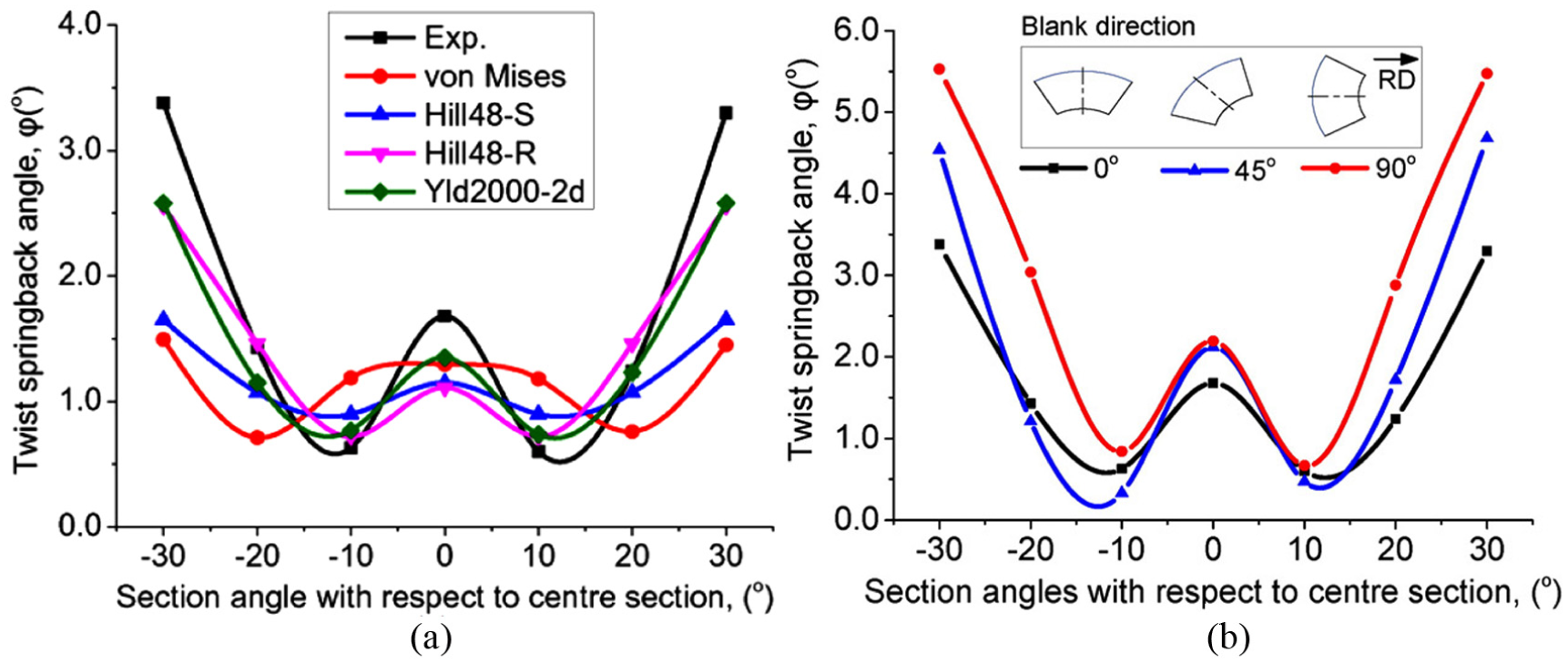
(a) Comparison of twist spring-back angle calculated using yield criteria (numerically) and experimental setup and (b) experimental calculation of twist spring-back for different rolling direction. 136
The FEA was performed by Muthler et al. 138 and demonstrated that p-extensions which are high-order solid elements can be effectively used for computing elastic spring-back of thin-walled structure, whereas anisotropic three-dimensional continuum elements can be effectively used for the discretization. A static explicit FEM was proposed by Jung 139 to solve the problems which can be solved using static implicit method applied to drawbead process with spring-back effect. This approach avoids the convergence which requires more computational time and provides data related to size and shape of the bed which helps in tool design.
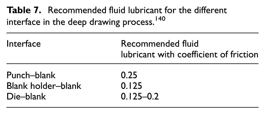
The prediction of thinning and spring-back action was carried out by Zein et al. 140 for deep drawing of a cup. To reduce the computational time, the boundary conditions and anisotropic material properties were defined for one-quarter three-dimensional FE model and solved using explicit analysis. The variation in spring-back was observed in sheet metal for the sake of change in die shoulder radius and punch nose radius (see Figure 29(a) and (b)). The study recommends for maintaining a die shoulder radius 10 times the sheet thickness, whereas punch nose radius 4 times the sheet thickness. Along with these two parameters, the coefficient of friction has also impact on deep drawing process (see Figure 30). The coefficient of friction suggested the different interface in deep drawing process (see Table 7).
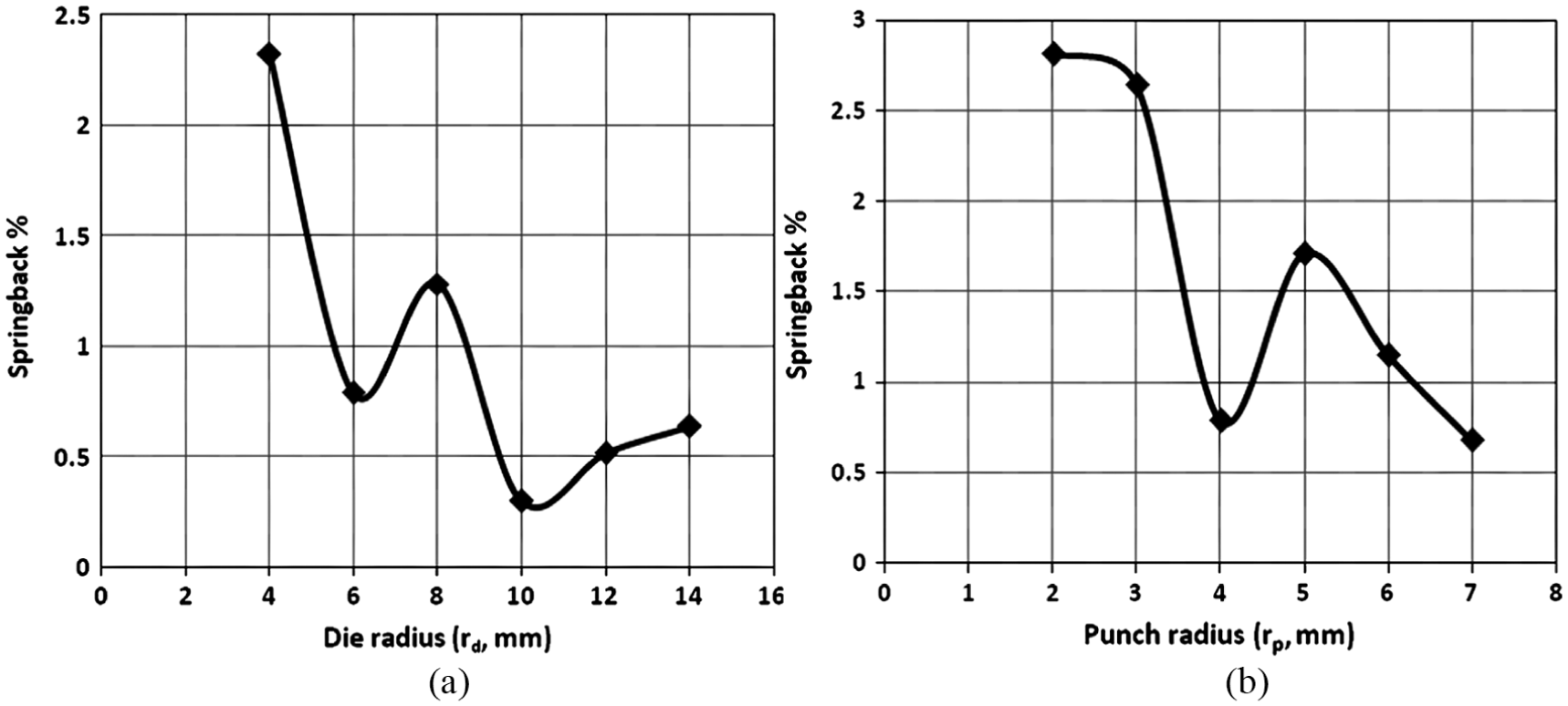
Variation of the spring-back percentage in sheet metal with the (a) die shoulder radius (rd) and (b) punch nose radius (rp, mm). 140
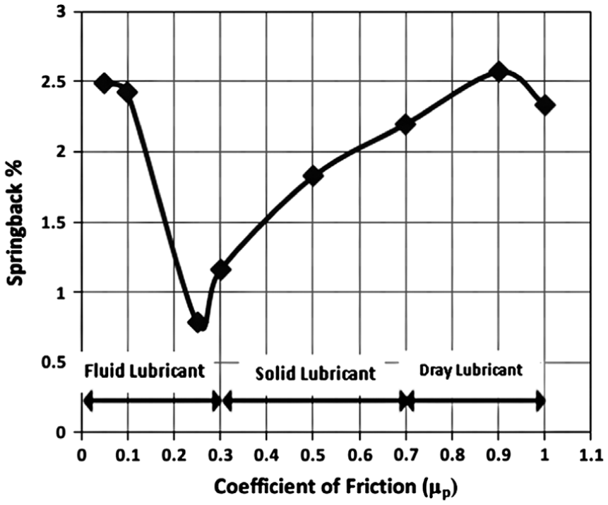
Effect of coefficient of friction between punch/blank on variation of the spring-back percentage in sheet metal. 140
Recommended fluid lubricant for the different interface in the deep drawing process. 140
Ul Hassan et al. 141 used pre-strain-based multiple cyclic stress–strain curves to predict the spring-back effect for DP 600 material with different magnitude. The numerical simulation was performed using Cha-boche–Roussilier model, anisotropic hardening model and Yoshida–Uemori model for the prediction of spring-back for tunnel geometry and hat geometry, whereas gas-forming process simulation was carried out by Yasar 142 for the prediction of spring-back effect in deep drawing of aluminium cylindrical cup. The effect of die design parameters and detonation pressure was investigated by performing implicit dynamic and explicit analyses. In a case of the micro deep drawing of circular cup Luo et al. 143 performed spring-back simulation and observed that the overall spring-back was influenced by surface roughness by taking into consideration a size effect and variance in material properties for Voronoi models.
Conclusion
The deep drawing process is used for drawing a component with a complex profile having a significant drawing depth compared to its diameter. The material with the property of high formability usually preferred for deep drawing process.
In the deep drawing process, certain defects are observed which directly affect the quality and manufacturing cost of the product. Mostly, the wall thinning effect is observed while performing deep drawing operation, which leads to the failure of the component. The flange wrinkling and spring-back effect are observed due to insufficient blank holding force and elastic behaviour of the material.
The observed wall thinning in a cup can be predicted by performing analytical, numerical and experimental tests. The Hill’48, Von Mises, and Barlat Yld’91 models are used effectively with FE analysis for the prediction of thickness variation. The thinning effect is more influenced by the parameters such as punch radius, die radius, BHF and lubrication. For few cases, the dry lubrication acts better than wet lubrication. The thickness variation in a micro deep drawing is reduced using techniques such flexible die and DLC film–coated blank holder dies.
The thickness variation of deep drawn cup depends on the behaviour and formability of the material. In the case of coated metals, the thickness variation depends on principal stress which is analysed using GTN damage model. The deep drawing ratio of multilayer sheets and the composite material is increased with increase in temperature. At 200 °C, the Al/Mg/Al multilayer composite sheet has fewer tendencies of thinning than 150 °C.
The wrinkling at the flange region can be predicted using theoretical models such as Hill–Hosford yield criteria and Hill’s bifurcation criterion. The wrinkling observed in pure aluminium sheets is predicted using different techniques such as an ANN, wrinkling limit diagram, energy method and multi-criteria design approach with RSM. The FEA with continuous damage mechanics is used for prediction of wrinkling in nickel-coated metals. In a case of fibre glass/PA66 prepreg, wrinkling is suppressed by increasing temperature and decreasing the strain rate and shear stiffness. The wrinkling can be avoided in composite with fibre-reinforced polypropylene by maintaining interaction between temperature and BHF.
The wrinkle formation in pre-bulging hydromechanical deep drawing process can be eliminated by reducing the tangential compressive stress on the unsupported region and increasing the area of sheet adhered to punch surface. The wrinkling distribution can also be improved using VBHF trajectories method, slab method and constant volume of a material method.
The Taylor’s theory for elastic–plastic media with aspects of Sach’s theory can be used for spring-back prediction with less time and low cost. The spring-back angle in valley region is decreased with an increment of punch radius and punch angle. The prediction of spring-back can be done using multi-cyclic stress-strain curves generated from FE simulation and gas forming process simulation. The surface roughness and variation in material properties affect the spring-back action in case of the micro deep drawing of a cup.
The objective of the review is to suggest an appropriate technique as per the type and behaviour of material for different drawing conditions in order to achieve uniform thickness variation in drawn cup. The analytical, numerical and experimental approach need to be utilized together to carry out deep drawing process in order to minimize the cost, time and defects such as thinning, wrinkling and spring-back. The study has skipped the multi-stage deep drawing process which will be used for drawing the component with high drawing depth, and complex profile need to be focused in future. Also, the parameters such as drawing speed and tooling temperature need to be focused in case of the deep drawing of composite materials. These could offer an excellent opportunity in the field of automotive industries for manufacturing lightweight cars.
Footnotes
Declaration of conflicting interests
The author(s) declared no potential conflicts of interest with respect to the research, authorship and/or publication of this article.
Funding
The author(s) received no financial support for the research, authorship and/or publication of this article.