
Abstract
Aiming at the issue of the lack of the design theory for the three-dimensional elliptical vibration cutting device, a compliant mechanism with two rotations and one translation is synthesized based on the theory of freedom and constraint topologies. And a three-dimensional elliptical vibration cutting device is proposed on the basis of the compliant mechanism. The relationship between the critical speed and the length of the tool bar is analyzed. Simulation is conducted to analyze the influence of parameters on the output ellipse. Experiments are conducted to verify the validity of the elliptical vibration cutting device. The relationship between the roughness and the cutting speed is obtained. Experiments with different driving frequencies are conducted without the change of other parameters. Results show that the proposed compliant mechanism is feasible for the elliptical vibration cutting device. Compared with the common cutting, the new elliptical vibration cutting device has a better performance in the processing effect. This provides an important reference for design of the elliptical vibration cutting device.
Keywords
Introduction
Processing quality can be improved by vibration cutting because the cutting force, the cutting heat, and the tool wear are greatly reduced. As an important branch of vibration cutting, three-dimensional elliptical vibration cutting (EVC) has drawn extensive attention in recent years. However, the types of the three-dimensional EVC device cannot meet the growing requirements because of the lack of the design theory.
Shamoto et al.1,2 developed a three-dimensional EVC device on the basis of the two-dimensional EVC. Shamoto and Suzuki 3 also demonstrated that EVC considerably improves cutting performance in terms of tool life, surface quality, and applicability to free-form surface machining and micromachining. Jung et al. 4 clarified the mechanism of undesirable vibration observed during high-efficiency EVC. And the mechanism is investigated by analyzing the finished surfaces and the undesirable vibrations superimposed on the elliptical vibration. Loh and Kim 5 developed an analytical model describing the elliptical path of the tool. Based on the analytical model, the distortions in the elliptical trajectories created at various frequencies were corrected for tilt and aspect ratio by changing the phase and relative magnitude of the sinusoidal excitation voltages. Nosouhi et al. 6 presented a novel analytical model for prediction of forces in elliptical vibration-assisted turning using a dynamic friction model. The cutting forces are determined by incorporating the friction forces calculated from the model. Amini et al. 7 designed an elliptical ultrasonic–assisted turning tool, in which the longitudinal and bending vibration modes have the minimum resonance frequency difference, so that the resonance of both the vibration modes can be achieved in a definite frequency. Zhou et al. 8 proposed a double-frequency EVC apparatus, which combined fast tool servo and EVC. Bai et al. 9 presented the predicted model of orthogonal cutting force, which was helpful to explain the phenomena that EVC could reduce the cutting force, lower cutting temperature, and improve the surface integrity. Yin et al. 10 developed a novel single-driven ultrasonic EVC device with a complex-beam horn. Compared to conventional cutting, the cutting force and surface roughness can be reduced with the device. Lu and colleagues11,12 designed an EVC device with parallel compliant mechanism. The structure is convenient to process, and the driving force is controlled under a lower value. Li et al. 13 and Lin et al. 14 propose a non-resonant three-dimensional EVC equipment to achieve both a high surface quality and complex surface shape. Although researchers have developed a variety of three-dimensional EVC device, there is no system theory applied to design of the EVC structure. Designer without years of experience cannot generate a possible design that would satisfy a given motion requirement. Hopkins and colleagues15–17 presented the method of the freedom and constraint complement topology for design of compliant mechanism with complex motion. This method embodies all possible design solutions.
Any designer can synthesize a suitable the EVC device even without enough experience if the theory is applied for design of the EVC device successfully. And a large number of EVC devices with different performance can be synthesized. Application of the freedom and constraint topologies theory to the design of the EVC device is significant for the development of three-dimensional EVC.
Based on the theory of freedom degree and constraint topologies, we have developed a novel three-dimensional EVC device. The stiffness matrix of the three-dimensional EVC device is derived according to screw theory. Finite element analysis is conducted to verify the correctness of the matrix. Experiments are carried out to obtain the relationship between the roughness and the cutting speed, and the change law of the surface roughness with the driving frequency is acquired. And the feasibility of the freedom and constraint topologies (FACT) theory for the design of three-dimensional EVC device is verified by the result of simulation and experiment.
Synthesis of the compliant mechanism with two rotations and one translation
The freedom and constraint of a compliant mechanism can be expressed as force and kinematic screw, respectively, in screw theory. The freedom of a compliant element in a compliant mechanism is defined as 15

where
The wrench constraint of a compliant element in a compliant mechanism can be defined as

where
A twist is complementary to a wrench if the reciprocal product of a twist and a wrench is equal to zero. The equation can be expressed as 15

Equation (3) can be simplified to the following equation

where
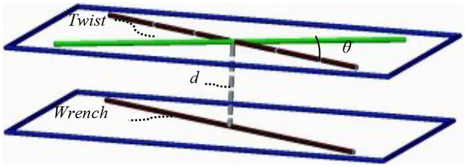
The relationship between a twist and a wrench. 15
The above derivation is the basis of FACT theory. And all the freedom and constraint space can be obtained from equation (4). FACT proposed all kinds of desired motions such as rotational and translational degrees of freedom. 15 Designer can select possible constraints within the constraint space to obtain required kinematics. Two rotations and one translation are required for our three-dimensional EVC device. The case 3 in FACT theory consists of all systems that contain three non-redundant constraints like the third line added to two intersecting lines, the third line added to two parallel lines, the third line added to two screw lines and so on. 15 Among these types, type6 meets our requirements perfectly. Then the freedom and constraint space case3 type6 is selected, which is shown in Figure 2.
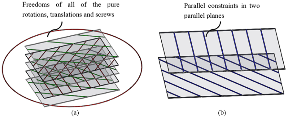
Freedom and constraints spaces of case3 type6: (a) freedom space and (b) constraint space. 15
In the constraint space in Figure 2(b), two parallel constraints are chosen in one plane, and in the other plane, a constraint that is perpendicular to the two constraints is chosen. The positions of the three constraints are shown in Figure 3.
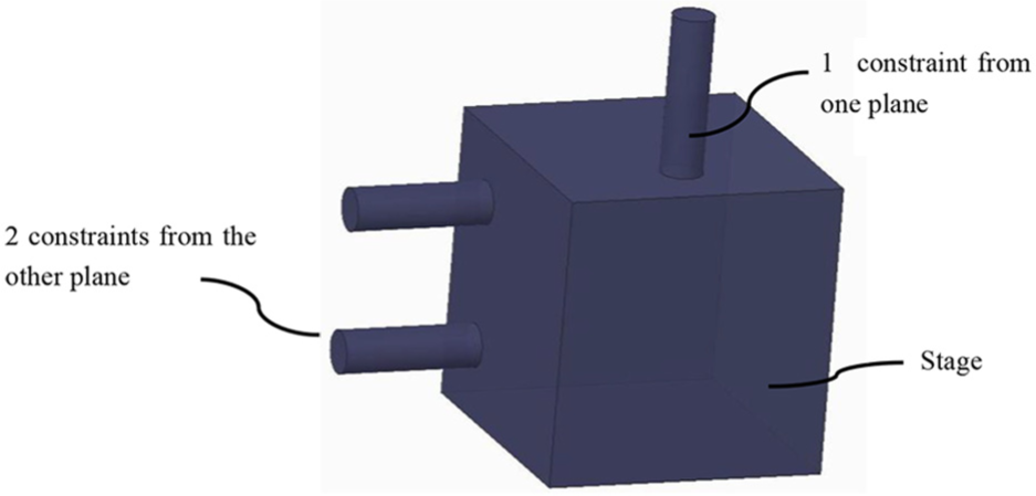
Layout of the three constraints.
According to the constraints in Figure 3, the compliant mechanism with three freedom degree is synthesized in Figure 4. Two redundant constraints are added to increase stability of the mechanism and reduce thermal expansion errors. The stage is connected to the base by five compliant elements. The origin of the coordinate O-XYZ is set on the center of the surface. The direction vertical to the stage upper surface is Z-axis, the direction with only one compliant element is Y-axis, and then X-axis is determined by the right-hand rule. To obtain the relationship between input and output, local coordinate systems are established on the five compliant elements. The location vector
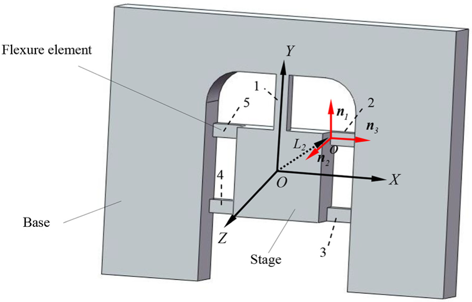
Parameters that define compliant mechanism.
The stiffness matrix links twist vectors to wrench vectors rather than displacement vectors to force vectors. The equation can be expressed as 13

where
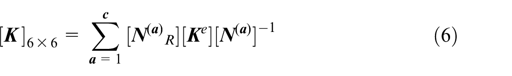
where
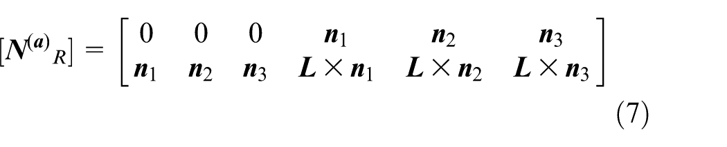
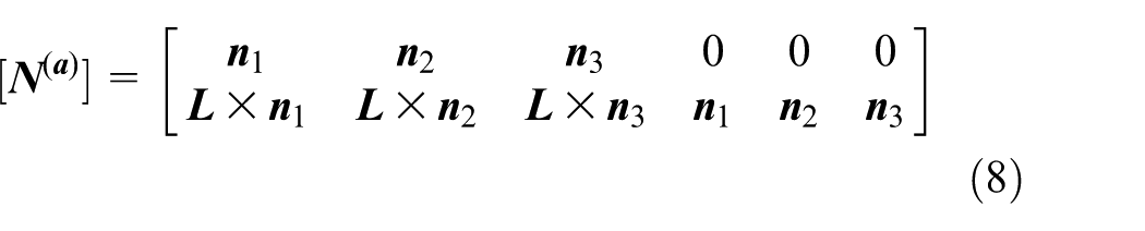
where
Then
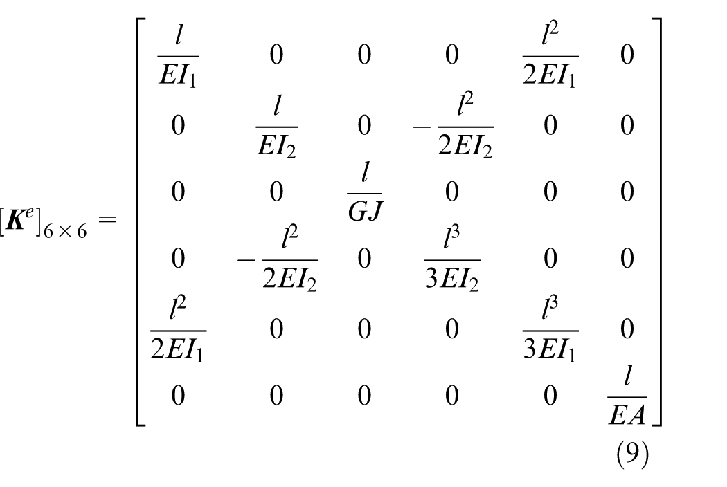
where
For compliant element 1, the location vector is
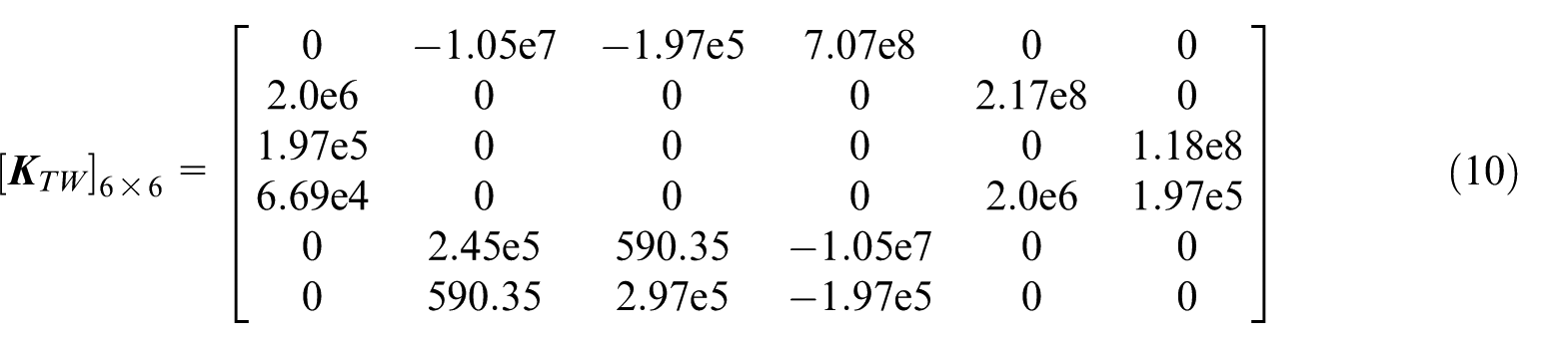
In order to verify the correctness of the stiffness matrix in equation (10), simulation is carried out in the ANSYS software. In the finite element analysis, the boundary conditions and assumptions should be consistent with equation (5). Since the working condition in reality is considered as a linear problem with small deformation, the stage is replaced by five constraint element mpc184, and beam4 element is selected as the compliant element. The finite element model is shown in Figure 5(a). For the compliant elements, one node of beam4 is connected rigidly with one node of mpc184 element, and the other node of beam4 is constrained in all freedom degrees. The force along Z-axis, the torque around Y-axis and X-axis are applied on the point O in the middle of the rigid body, respectively. Figure 5(b) shows the rotation angle contour of the compliant mechanism around Y-axis if the torque around Y-axis is acted on.
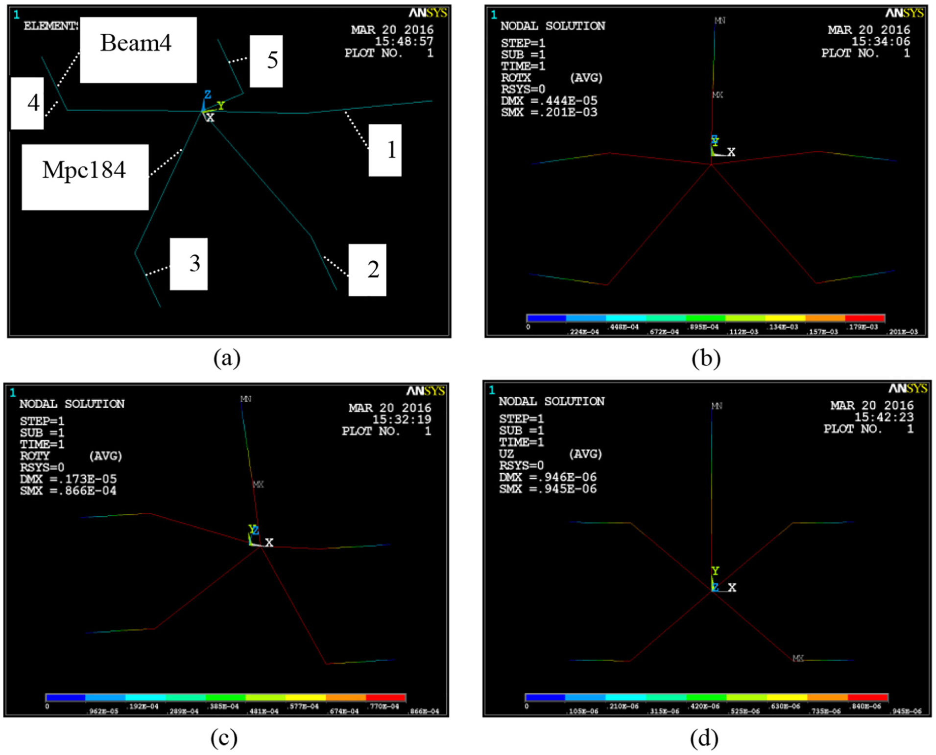
The displacement and rotation angle contour of the mechanism: (a) FEA model of the compliant mechanism, (b) rotation angle around Y-axis, (c) rotation angle around X-axis, and (d) displacement along Z-axis.
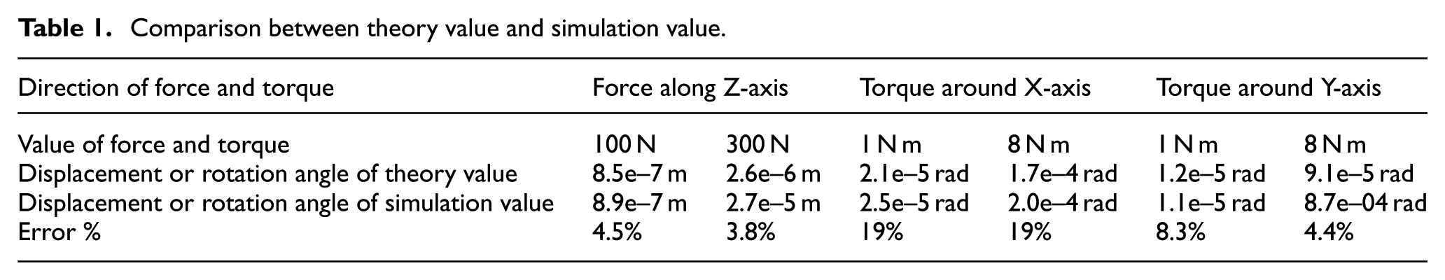
The direction and loading position of the force and torque are constant, and the value of the force or torque is gradually increased. The simulation and theory value of displacement and rotation angle are shown in Table 1. The error of the theory value and simulation value in Z-axis is minimum, which is less than 5%, and the rotation angle error around X-axis is maximum, which is about 19%.
Comparison between theory value and simulation value.
The dynamic characteristic is the main performance for the EVC device. To obtain the natural frequency and main vibration mode, modal analysis is conducted in ANSYS software. The element type is selected as solid45, and the aluminum alloy material is chosen. The density of the material is 2700 kg/m3, the elastic modulus is 73 GPa, and the Poisson ratio is 0.3. The first sixth-order modes of the mechanism are obtained. The first sixth-order vibration natural frequencies are shown in Table 2. We should avoid the resonance frequency region during processing.
The first sixth-order vibration natural frequency.

Figure 6 shows the vibration types of the compliant mechanism. The first-order vibration type of the compliant mechanism is translation in Z-axis. The second-order vibration type is rotation around Y-axis. The third-order vibration type is rotation around X-axis. All the vibration types are consistent with the degree of freedom.
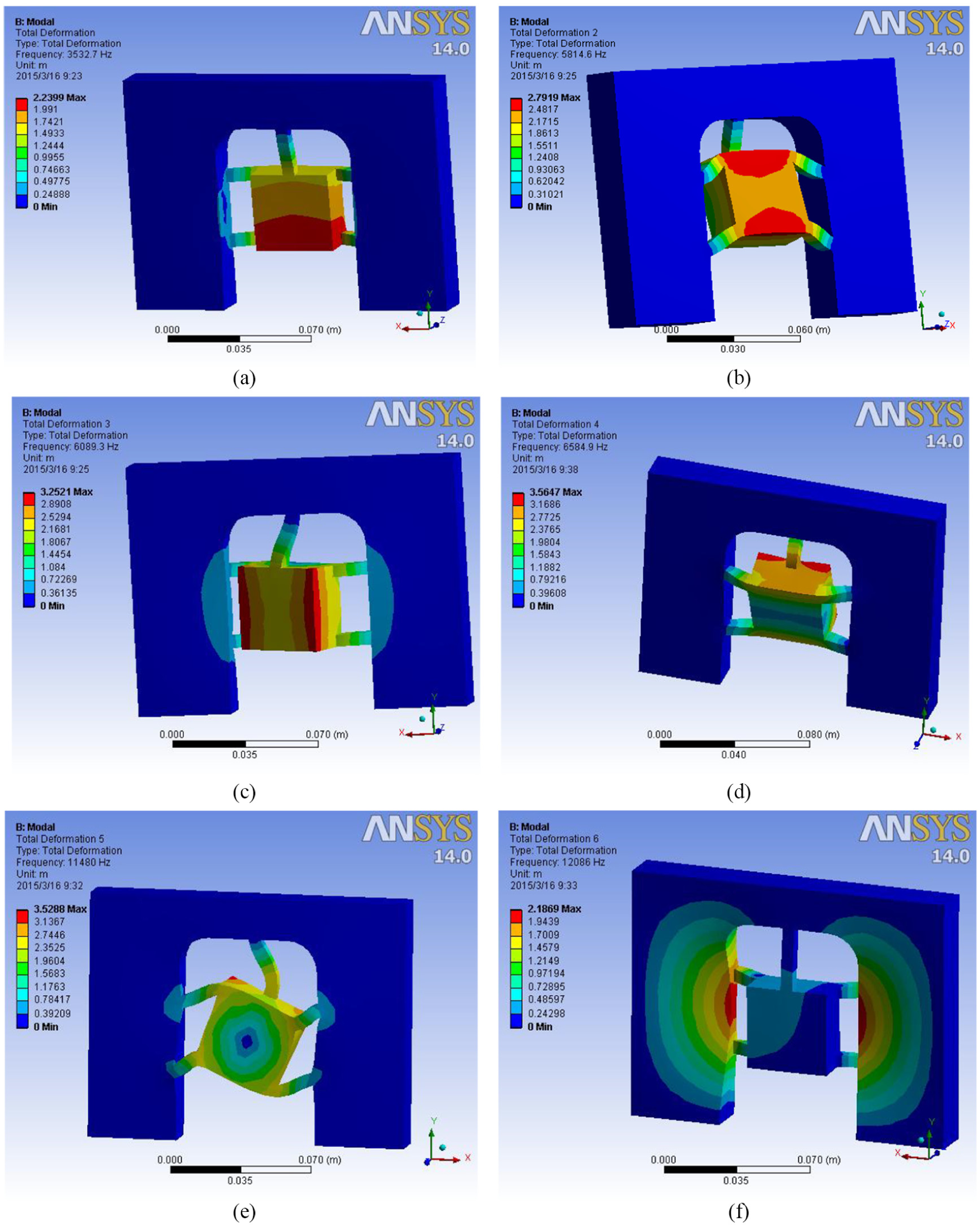
Vibration type of the first six modal: (a) the first-order vibration type, (b) the second-order vibration type, (c) the third-order vibration type, (d) the fourth-order vibration type, (e) the fifth-order vibration type, and (f) the sixth-order vibration type.
Design of EVC device based on the parallel compliant mechanism
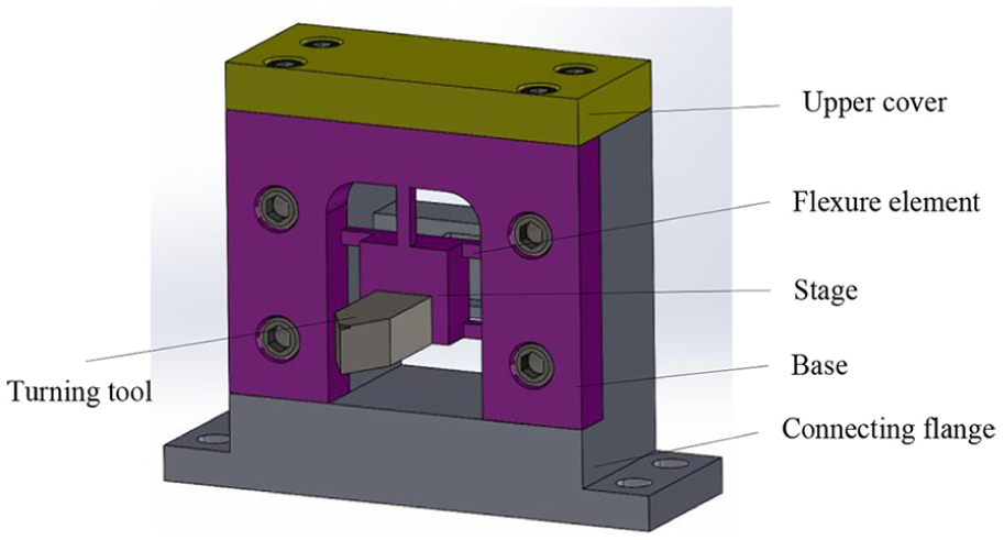
A novel EVC device is developed based on the above parallel compliant mechanism. The turning tool is mounted on the stage, which is shown in Figure 7. Point A and point B on the stage are set as driving points. Torque around Y-axis and force along Z-axis can be obtained if point A is driven. Then the rotation around Y-axis and the displacement along Z-axis are outputted on the tip of turning tool. Similarly, the rotation around X-axis and the displacement along Z-axis are outputted on the tip of turning tool by driving on point B. Therefore, the ellipsoid envelope can be obtained if the phase difference, frequency, and amplitude can be controlled as required.
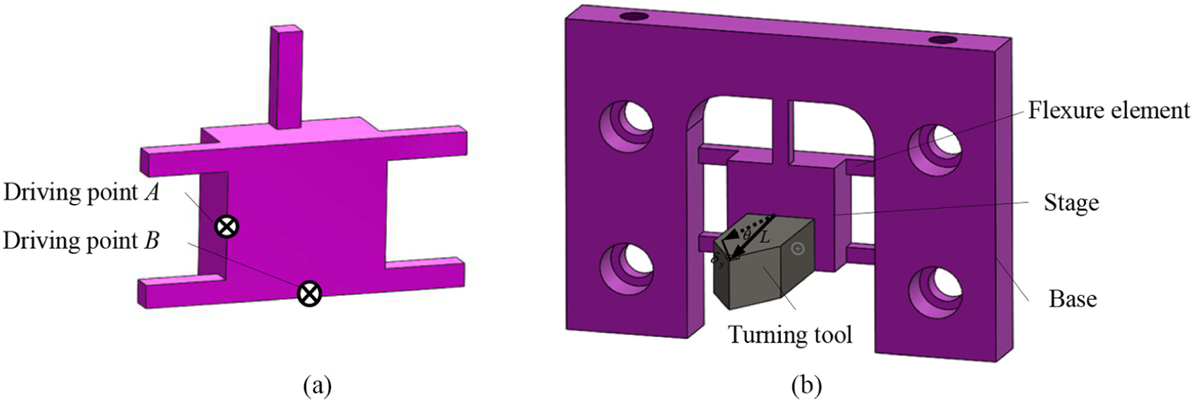
The prototype of the novel EVC device: (a) the driving points A and B and (b) the rotating angle θ of the stage around X- or Y-axis, and the length L of the turning tool, and the displacement δx(y) on the tip of turning tool.
In Figure 7(b), the rotating angle of the stage around X- or Y-axis is denoted as

Thus, the amplitude of the tip can be improved by increasing the length of the tool bar. For the separation type vibration cutting, the critical velocity can be improved by improving the amplitude of the tip. Then a wider range of spindle speeds can be adapted for the vibration stage.
If the actuators on point A and point B are driven, the new positions of points A, B, C, and D are changed to points A1, B1, C1, and D1. These positions are shown in Figure 8. The displacements of A, B, C, and D along Z-axis are
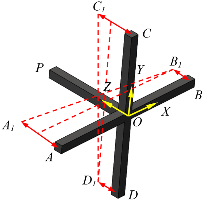
The simplified model of the EVC device.
where
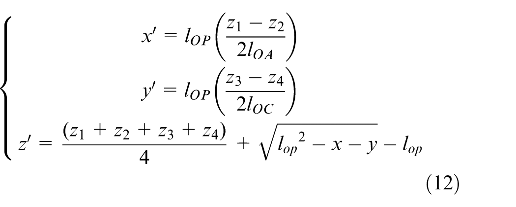
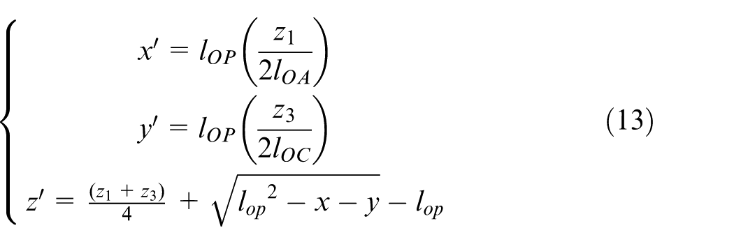
If the driving signals
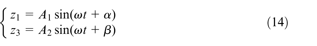
According to equations (13) and (14), ellipse trajectory is decided by the parameters as follows:
Amplitude of the actuators
Initial phase of the actuators
The distances between the center of the stage and the driving points
Length of the turning tool bar
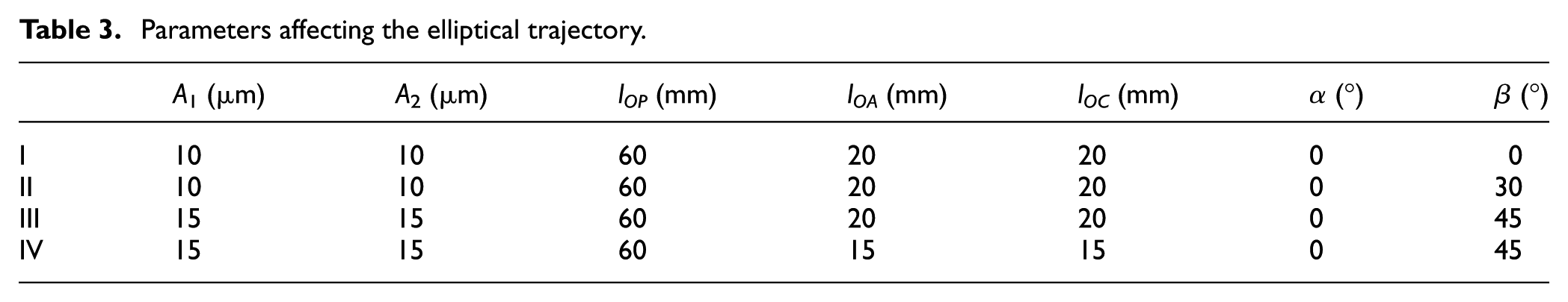
To verify the feasibility of the compliant mechanism for ellipsoid envelope output, simulation is conducted in ANSYS software. Parameters are selected in Table 3.
Parameters affecting the elliptical trajectory.
The coordinates of the simulation output are plotted into the ellipse trajectory in the MATLAB software, which are shown in Figure 9. Results show that the angle between the projection of the ellipse long axis and the coordinate axis in the X-Y plane is influenced by initial phase
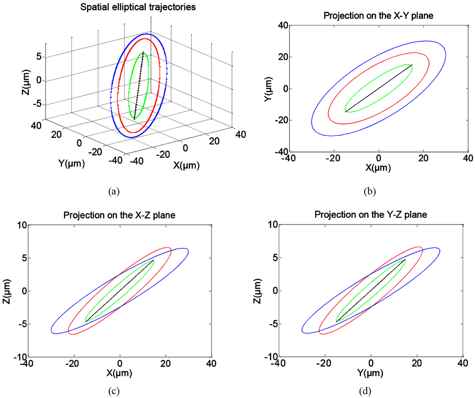
Elliptical trajectories with different parameters: (a) spatial elliptical trajectories, (b) projection on the X–Y plane, (c) projection on the X-Z plane, and (d) projection on the Y–Z plane.
According to the simulation results, the driving position distribution and the stiffness requirement are determined. And all the parameters of the EVC device are determined. Then the whole structure of the novel EVC device is designed as shown in Figure 10.
The whole structure of the EVC device.
Experiments
Two PSt150/10X10/20 piezoelectric actuators are selected to generate the driving force. The working frequency of the piezoelectric actuator is 0–2000 Hz. The maximum output displacement of the piezoelectric actuator is 18 μm. And the maximum displacement in Z direction of the compliant mechanism is 11.8 μm after the piezoelectric actuator is assembled to the EVC device. The phase difference of the piezoelectric actuator power is setup to be 90°. The input parameters are guaranteed by the driving equipment. And the input displace is measured by the capacitive displacement sensor. The output displacement is measured by the laser distance measuring instrument. The output displacement is measured by the laser distance measuring instrument LK-G5000, KEYENCE. Sumitomo TP2500 hard alloy coating turning tool is applied in this case. The EVC device fixed on the lathe is shown in Figure 11.
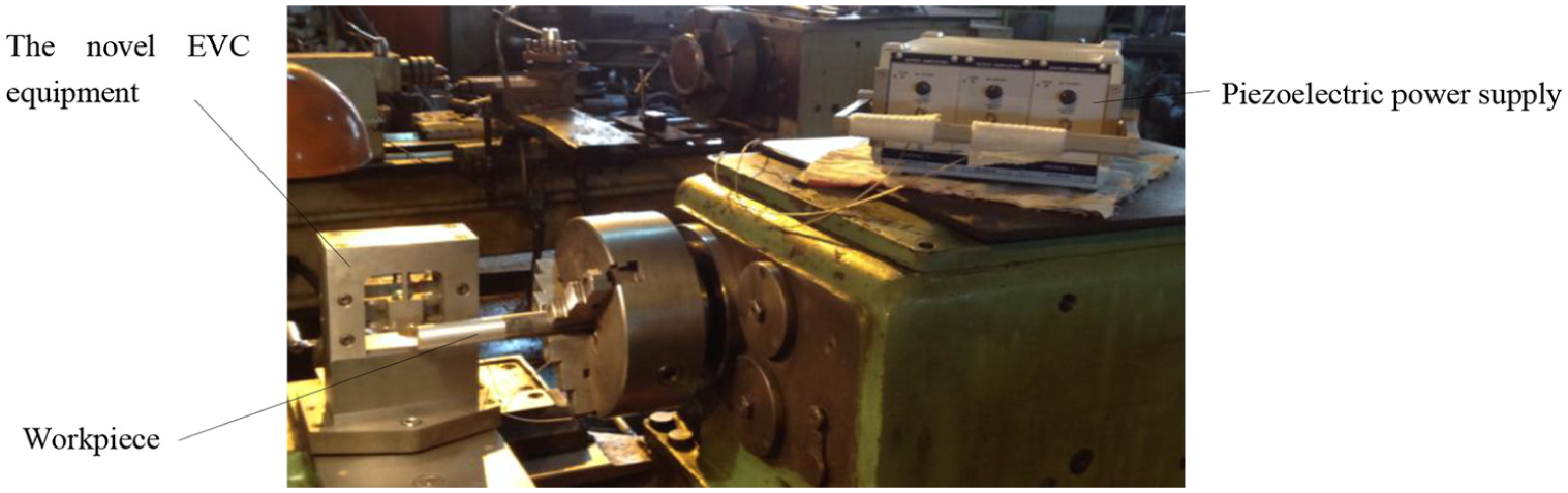
The EVC device fixed on the lathe.
Q235 bar is selected as the processing object. After rough turning, finish turning is conducted on two sections of the Q235 bar. On one section, the EVC device is turned on. On the other section, the EVC device is turned off. The same cutting parameters are used during the two sections. The main shaft speed is set as 500 r/min. The feed rate is 0.1 mm/r. The back engagement of the cutting edge is 0.1 mm. And the working frequency of the EVC device is adjusted to 2000 Hz. In the end, the machined surface of the Q235 bar is shown in Figure 12.
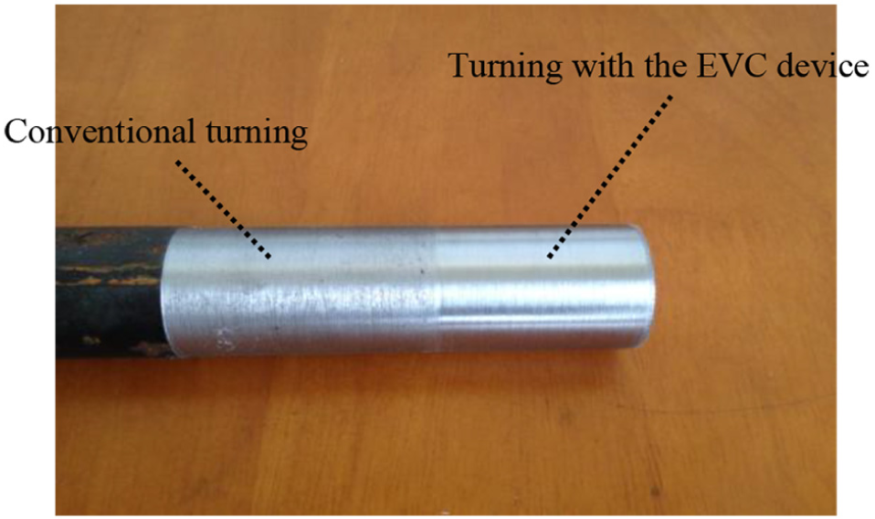
Comparison of the conventional turning and the turning with the EVC device.
As shown in Figure 12, cutting surface quality with the EVC device vibration is obviously superior to the conventional cutting. Figure 13 shows the two different turning surfaces with an optical microscope. Results show that the cutting quality is improved obviously with the EVC equipment.
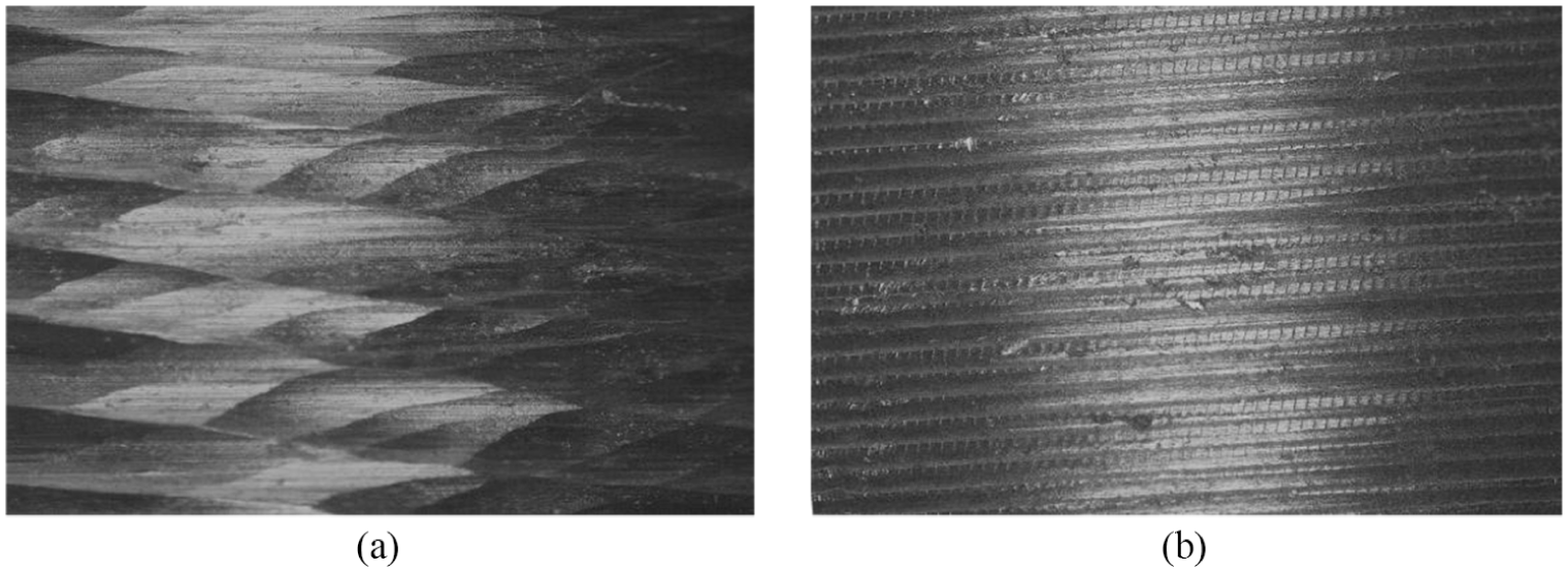
The turning surface micro-graph with two different machining types: (a) conventional turning and (b) turning with the EVC device.
The two different cutting surfaces are measured on the roughness measuring instrument, which is shown in Figure 14. Results show that roughness of the conventional cutting surface is 9.912 µm and roughness is 3.446 µm on the surface of three-dimensional elliptical vibration turning.
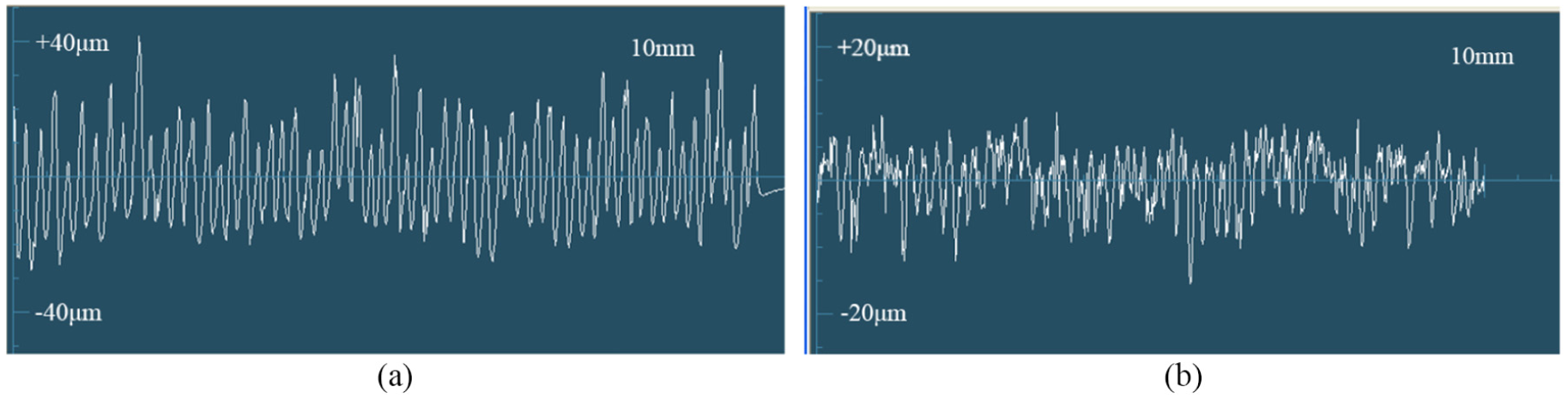
Roughness of different machining types: (a) surface roughness of conventional turning and (b) surface roughness with the EVC device.
In order to study the critical speed of the new EVC device, the cutting speed is changed under the same condition of other cutting parameters. The feed rate is set as 0.1 mm/r, the back engagement of the cutting edge is set as 0.1 mm, and driving frequency is set as 2000 Hz. The relationship between the roughness and the cutting speed is shown in Figure 15. Results show that the surface roughness decreases with the increase of the shaft speed during the range of 500–575 r/min. But the surface roughness increases with the increment of the shaft speed if the cutting speed is larger than 575 r/min. Therefore, the critical speed of the new EVC device is closed to 575 r/min.
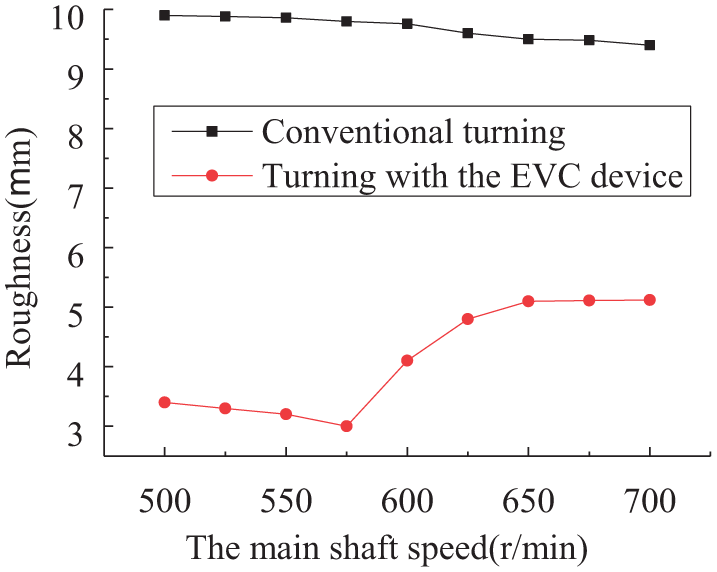
Roughness change law with different shaft speeds.
To obtain the change law of the roughness with the driving frequency, experiments are conducted with different driving frequencies. The main shaft speed is 500 r/min. The feed speed is 0.1 mm/r. And the cutting depth is 0.1 mm. Results show that the roughness of the bar decreases with the increment of the driving frequency, while the effect is not obvious if the driving frequency is more than 1000 Hz. The change law of the surface roughness with the driving frequency can be shown in Figure 16.
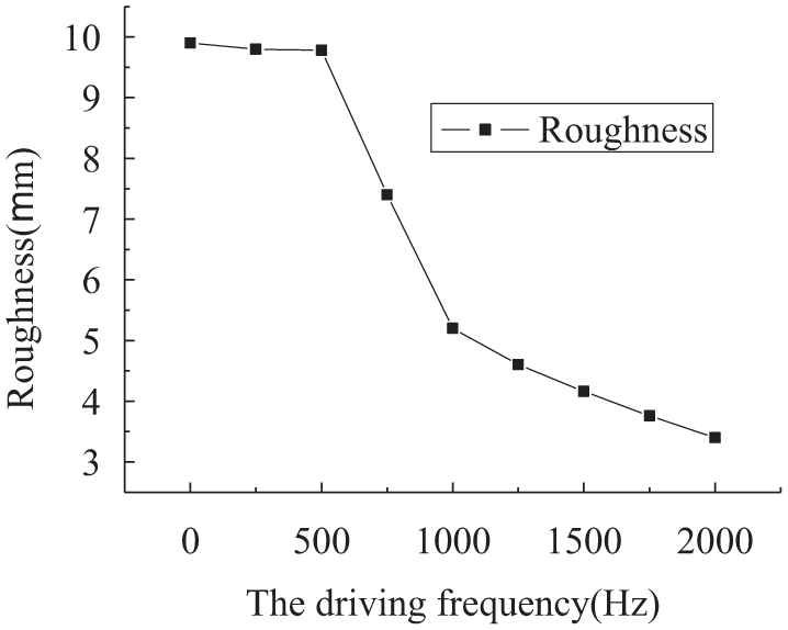
Change law of the surface roughness with the driving frequency.
Conclusion
FACT theory is applied to design an EVC device. Simulation and experiments are conducted to verify the validity of the device. And the influence of parameters on the machining effect is discussed. The specific results and conclusions are as follows
A three-dimensional EVC device with two rotations and one translation is proposed based on the FACT theory. The stiffness matrix of the compliant mechanism is derived. The relationship between the critical speed and the length of the tool bar is analyzed.
Simulation results show that the phase difference of the driving signal
Experiments results indicate that roughness of the three-dimensional elliptical vibration turning surface is far less than the conventional cutting surface. The critical speed of the EVC device is closed to 575 r/min. The roughness of the bar decreases with the increase of the driving frequency. The influence is not obvious if the driving frequency is more than 1000 Hz.
The above results show that the FACT theory is feasible for the EVC device. The successful application of the FACT theory in the design of three-dimensional EVC device will stimulate the development of a large number of three-dimensional EVC devices with different characteristics.
Footnotes
Declaration of conflicting interests
The author(s) declared no potential conflicts of interest with respect to the research, authorship, and/or publication of this article.
Funding
The author(s) disclosed receipt of the following financial support for the research, authorship, and/or publication of this article: This project is supported by Department of Education of Liaoning Province (Grant No. JDL2016027), National Natural Science Foundation of China (Grant No. 51775078), and Natural Science Foundation of Liaoning Province (Grant No. 20170540123).