
Abstract
Assembly process simulation has been recognized as an effective tool for design verification. The representation of actual part surfaces produced by manufacturing processes is an important issue for assembly simulation. Manufactured part surfaces can also be regarded as non-ideal surface morphologies caused by manufacturing errors. This article presents a new approach to describe non-ideal cylindrical surface morphologies. A deviation coordinate system is developed by adding a new deviation dimension along the normal direction of the nominal surface modeled in the cylindrical surface curvilinear coordinate system. Considering characteristics of the cylindrical surface machining process, a unified expression of combined Hermite polynomials and Fourier series is used to demonstrate deviations that commonly appear on manufactured non-ideal cylindrical surfaces. The Hermite–Fourier polynomials constitute multi-morphologies resulting from different manufacturing errors. In the proposed method, a parametric matrix is created from the expansion of the Hermite–Fourier polynomials. Each morphology can be represented by a corresponding matrix. The total deviation of a non-ideal part surface is the sum of deviations caused by each manufacturing error source through a linear combination of various matrices. The effectiveness of the proposed method is verified by a simulation of the sealing function of shaft-hole assemblies.
Keywords
Introduction
In mechanical assembly, the performance of two mating components largely depends on the contact status and clearance between their mating surfaces. The simulation of an assembly verifies the feasibility of the mechanical design and provides evaluation of the product performance.
Many studies on assembly incorporated assembly mating conditions, part features and assembly-related errors/deformations in their models and algorithms based on the geometrical data from computer-aided design files of an assembled product.1–4 More research work has been conducted in recent years on assembly analysis with consideration of non-ideal surface of the assembly.5–7 To obtain more realistic simulation results, more attention needs to be paid on the modeling of non-ideal surface.
In the modeling of non-ideal surface, Louhichi et al. 8 modeled the position and orientation defects of components based on the shape of the tolerance zone, the toleranced feature type and the tolerance type. Dantan and Qureshi 9 utilized convex hulls defined in the parametric space to simulate the influences of geometric deviations on the geometrical behavior of the mechanism. Anwer and colleagues10,11 investigated the fundamentals of skin models at a conceptual, geometric and computational level to address the geometric deviations.10,11 Schleich and colleagues5,6 proposed the skin model shapes paradigm by the superposition of the nominal surface and geometric deviations that are divided into systematic deviations and random deviations.5,6 This paradigm provides a method for the modeling, representation and analysis of geometric deviations. A method proposed by Zhu et al. 12 improved the application of the skin model shapes in tolerance analysis by emphasizing the effect of form deviation. Samper et al. 13 proposed to parameterize form deviations by building a geometric model based on the natural modal shapes of the ideal surface, which simplifies the consideration of surfaces with form defects in assembly simulation. With the application of the discrete modal decomposition, a surface with multi-scale deviations was simulated and evaluated with respect to tolerance specification by Cao et al. 14 Huang and Ceglarek 15 developed a mode-based method to characterize part geometric error using discrete cosine transform (DCT), in which the modes related to the manufacturing process error could be identified. Based on the measurement data, a manufacturing signature model was established by Colosimo et al. 16 and Wilma and Giovanni 17 to facilitate the representation of the actual profiles of manufactured surfaces.16,17 With the manufacturing signature and the assembly conditions, Corrado et al. 18 proposed a geometric model to simulate the assembly of parts with geometric deviations, based on which a new Computer-Aided Tolerancing (CAT) tool was developed.
Meanwhile, the modeling of cylindrical surface deviations has also drawn research interest. A typical method is the combination of the Fourier series and Chebyshev or Legendre polynomials, which has been employed to model cylindricity errors. Zhang et al. 19 introduced a unified functional tolerancing approach involving Legendre and Fourier polynomials for modeling and characterizing typical geometrical errors commonly found in machined cylindrical parts. Additionally, Ni and Yao 20 attempted to model the cylindricity errors with Legendre/Fourier polynomials and the effects of the cylindricity error on position accuracy are analyzed. Henke et al. 21 put forward two methods to model the cylindricity errors, one based on Chebyshev/Fourier polynomials and the other based on a linear combination of Eigen shapes derived directly from the measurement data.
Cylindrical surfaces are common geometric contact features in assembly. The morphologies of the manufactured cylindrical surfaces are attributed to various manufacturing errors and have been investigated by some existing literatures. Zhang et al. 19 studied the typical manufacturing errors, such as errors caused by spindle rotation, fixture distortion, misalignment of spindles and work centers, and workpiece deflections. The effects of those errors on manufactured surfaces are also investigated. Madden et al. 22 described a concurrent measurement of radial, axial and angular motions of spindle using concentric circle grating and phase modulation interferometers in order to depict the deviation of the manufactured surface from the nominal surface. Chien 23 expanded the approximated harmonic model which determines the amplitude spectra of harmonics of roundness profiles by adding the knowledge of machining process. Sawabe et al. 24 and Rahman and Venkatesh 25 indicated that the number of lobes on manufactured surface is related to the number of jaws on the chuck which holds the workpiece. Rao and Shin 26 and Sadílek 27 analyzed the workpiece deflection caused by the cutting force.26,27 Stavropoulos et al. 28 established the relationship between cutting time and tool wear and found it is linear in the nominal wear stage. Schindler et al. 29 proposed a finite element method to predict the deformations caused by thermal effects when dry turning aluminum alloys.
Many of the proposed models represent the manufactured surfaces either by discrete surface points or by the whole surface shape. A model that can represent the deviated surface with respect to its ideal design remains to be developed. It is necessary to develop a precise non-ideal surface morphology representation method for high-fidelity simulation modeling. The representation should consider the manufacturing errors that affect the final manufactured surface morphology. This article proposes deviation coordinate system (DCS) and Hermite–Fourier combination polynomials to express manufactured cylindrical part surface morphologies. The total deviations of the manufactured cylindrical surface can be easily calculated by the parametric matrices resulting from the expansion of the polynomials. The effectiveness of the method is verified through simulation and analysis of the sealing function of shaft-hole assemblies.
Coordinate representation and formation of the non-ideal cylindrical surface
The nominal cylindrical surface in cylindrical coordinate system
Due to the extensive application of cylindrical surfaces in product design, it is significant to establish an effective coordinate representation for cylindrical surfaces. For cylindrical surfaces, a cylindrical coordinate system (CCS)

The function represents a nominal cylindrical surface in a three-dimensional (3D) coordinate system, where
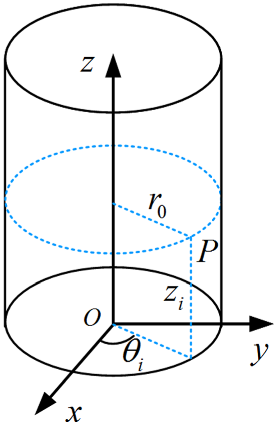
A nominal cylindrical surface in CCS.
Point

where
Relationship between non-ideal cylindrical surfaces and nominal surfaces
The performance of an assembled product is associated with the shape of mating component surfaces in the assembly. It is important to consider the effects of the manufactured surface shapes in the simulation analysis to achieve more practical and accurate understanding of the assembly performance.
For example, Figure 2 illustrates different non-ideal shaft-hole assemblies. In this figure, the hole is nominal, while the shaft is non-ideal and three non-ideal surface shapes are included in the assemblies. It should be noted that various non-ideal surface shapes that comply with the same tolerance zone
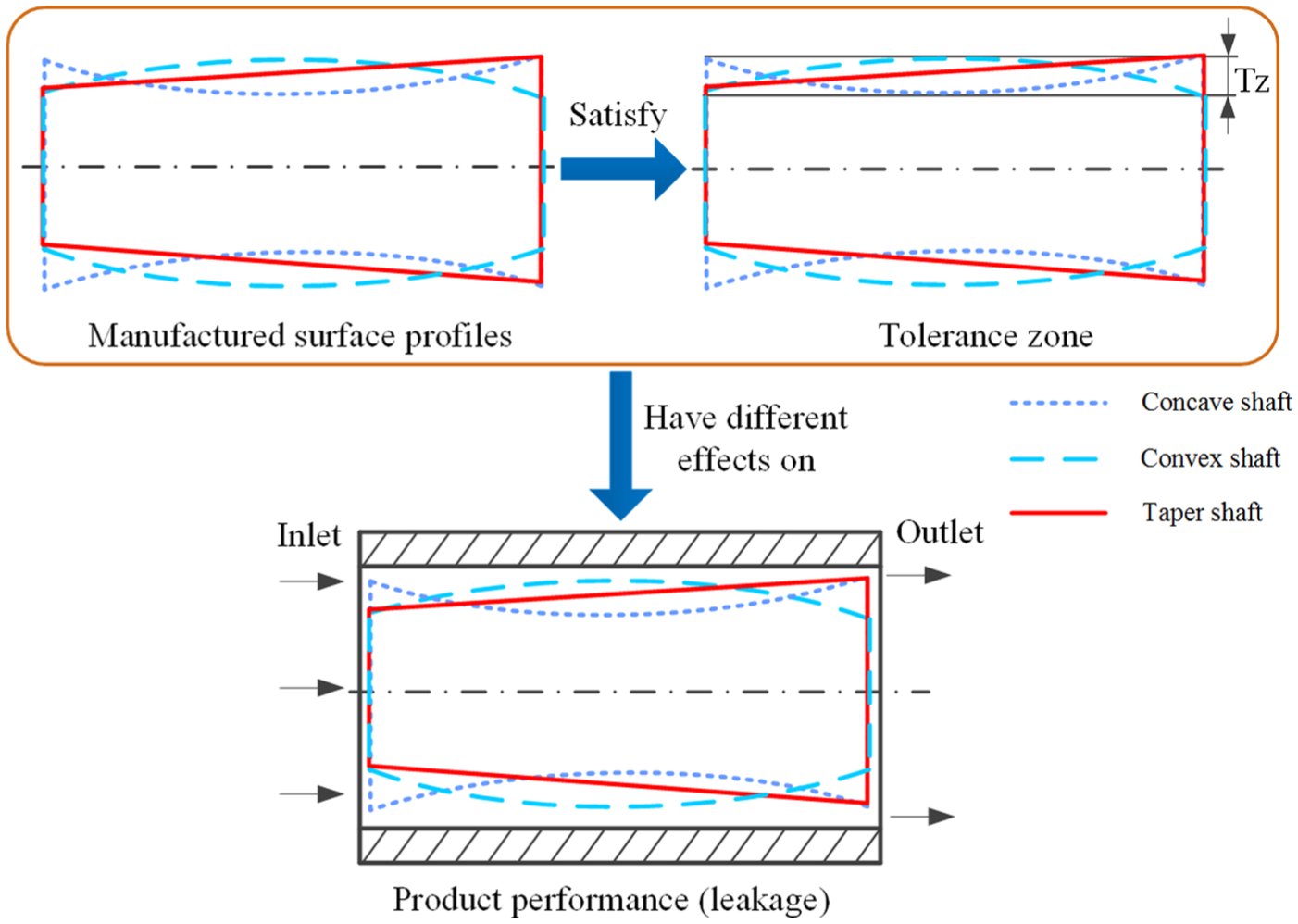
Illustration of the effect of different surface morphologies on product performance.
It is obvious from Figure 2 that the product performance varies significantly when the shape of the manufactured surface changes. Therefore, in order to capture this variability, the relationship between the non-ideal manufactured surface and the nominal surface should be studied.
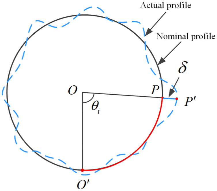
The manufactured non-ideal surface can be considered as a deviated state of its nominal geometry or ideal surface. Any point on the non-ideal surface can be corresponded to a point on the nominal surface, and be defined as a “deviation” of that point from its theoretical position. As shown in Figure 3, the non-ideal surface resembles a blanket that wraps the nominal surface, with the thickness at each point of the blanket as the corresponding deviation of that point. Thus, the non-ideal surface can be represented mathematically by the superposition of the nominal surface and deviations.
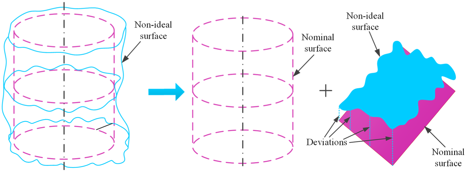
Relationship between non-ideal and nominal cylindrical surfaces.
With this relationship, the non-ideal cylindrical surface can also be represented in the CCS
Definition 1
According to the definition of the nominal surface in the CCS, a two-dimensional (2D) system—cylindrical surface curvilinear coordinate system (CSCCS)
In fact, the non-ideal surfaces could still be represented using CCS

Definition 2
A variable
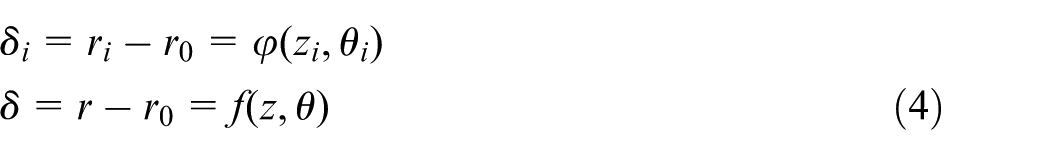
Equation (4), termed as “deviation function,” is a function in the CSCCS.
According to Definition 1, the deviation variable
Definition 3
Based on the CSCCS
It is known from Definition 2 that the non-ideal surface can be represented by one function in the DCS. Therefore, it can be treated as a surface in the DCS.
The non-ideal cylindrical surface in DCS
According to Definitions 2 and 3, the deviation
Representation of non-ideal surface in DCS.
In Figure 4,
According to the definition of the DCS, each point on the non-ideal cylindrical surface can be represented by the deviation coordinates in this coordinate system. And the deviation function established in this coordinate system has the following characteristics:
If
If
The distribution of the deviations can be plotted by the deviation function.
Such a definition of the DCS provides a clear and easy representation of non-ideal surfaces, which leads to simplified modeling and calculation of the non-ideal surfaces in computer-aided systems.
Formation of the non-ideal surface morphology
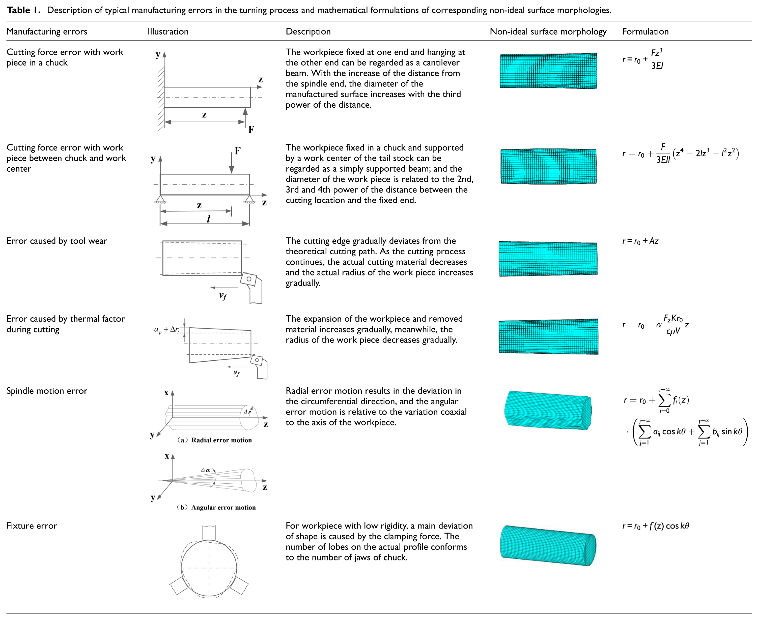
In a manufacturing process, the manufactured surface of the workpiece is not consistent with the nominal surface due to manufacturing errors. Under the influence of some typical errors caused by cutting force, tool wear, thermal factors, spindle motion error and fixture error, surface morphologies are introduced. Table 1 provides the description of the manufacturing errors as well as their corresponding non-ideal surface morphologies and mathematical formulations.
Description of typical manufacturing errors in the turning process and mathematical formulations of corresponding non-ideal surface morphologies.
Deviation modeling and parametric representation of the non-ideal cylindrical surface
Deviation modeling of the non-ideal surface
Two motions exist in a cylindrical turning process, namely main motion and feed motion as depicted in Figure 5. The main motion is a rotational motion of the spindle. The variations of spindle will result in the variation of the relative position between the workpiece and tool. The deviation on the manufactured surface resulting from the main motion is only related to the angle of rotation, and is therefore periodic.
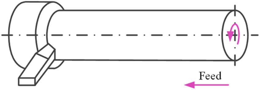
Two motions in cylindrical turning process.
Feed motion is the translation of the tool along the axis of the spindle. Deviations may occur due to force deformation caused by the equipment and cutting force and the variation of the tool tip geometry caused by heat and/or tool wear. Such deviations are generally dependent on the axial position, while unaffected by the rotation of the workpiece. The deviations of the manufactured surface during feed motion can be expressed by a function of the distance between the cutting location and the spindle end.
A manufactured cylindrical surface includes deviations both in the axial direction and along the circumferential direction, the former can be represented by polynomials and the latter is periodic.
Chebyshev and Legendre polynomials19,21 were adopted to demonstrate the deviations along the axial direction. Since the range of Chebyshev and Legendre polynomials is
Thus, Hermite polynomials and Fourier series can be used, respectively, to express the deviations along these two directions. The comprehensive expression of the cylindrical non-ideal surface deviations can be expressed by the combination of the Hermite polynomials and Fourier series, as shown in equation (5)
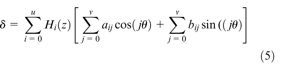
where
The Hermite polynomial sets
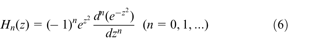
The first five Hermite polynomials are
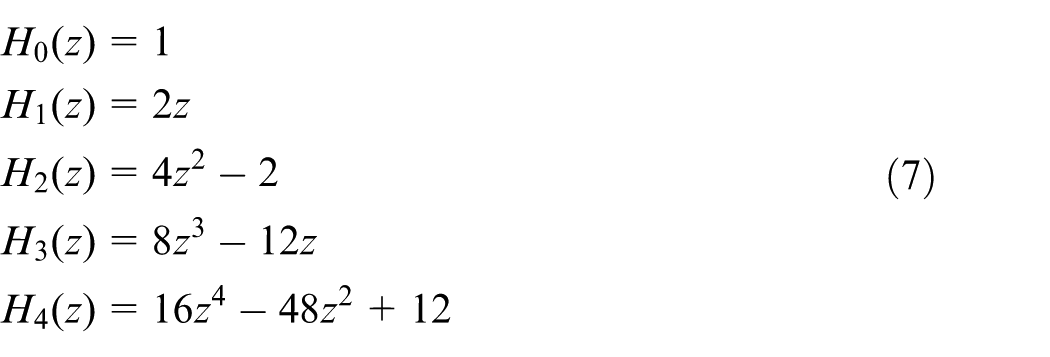
Each non-ideal surface morphology listed in Table 1 can be represented by a linear combination of several Hermite polynomials.
The selection of these two orthogonal functions conforms to the motion characteristics of the turning or grinding process. The orthogonality of these two polynomials facilitates the expression of the non-ideal surface.
From the above analysis, the Hermite–Fourier polynomials of typical non-ideal surface morphologies listed in Table 1 can be concluded in Table 2.
Hermite–Fourier polynomials of each non-ideal surface morphology generated by a certain error.
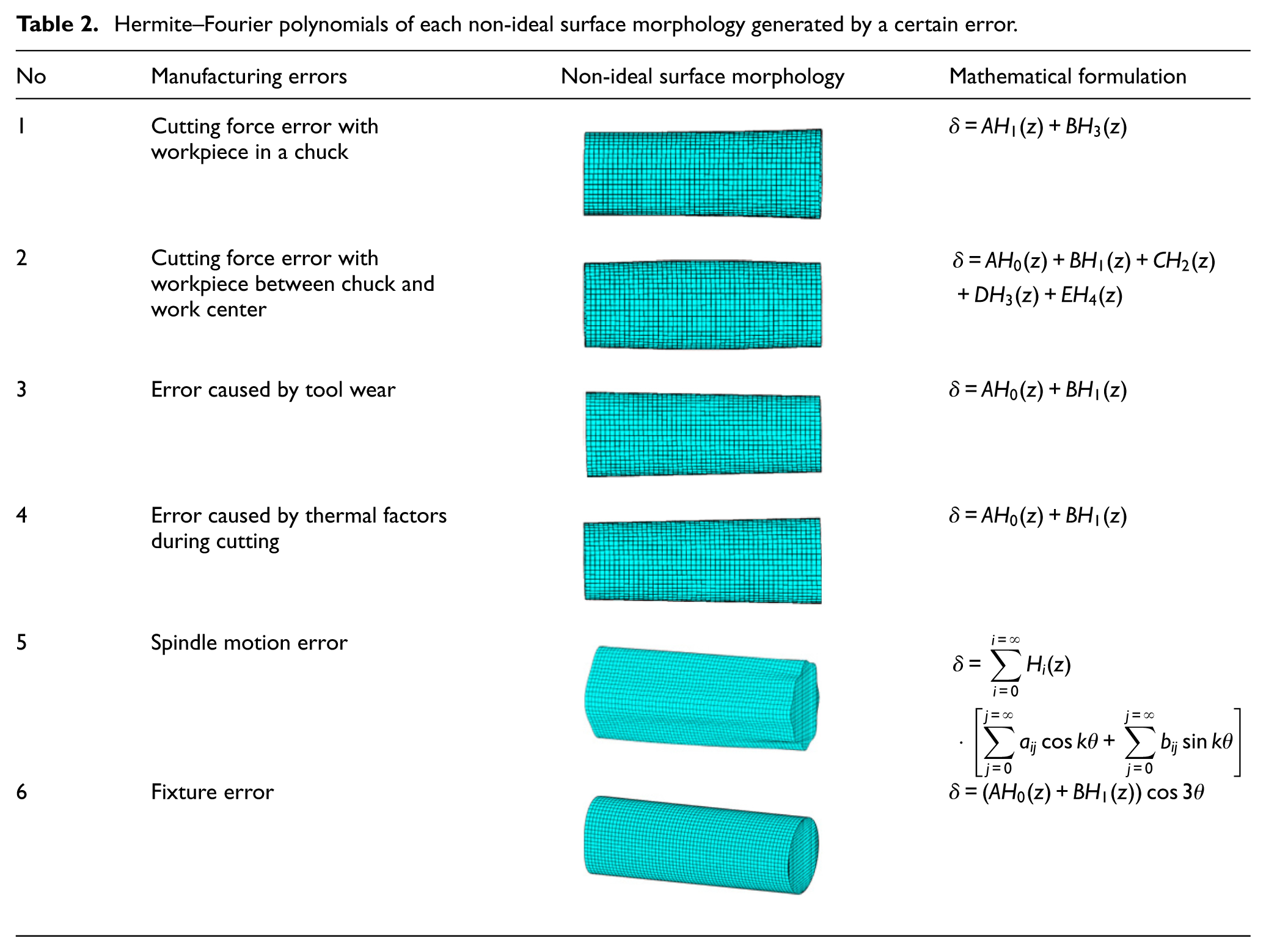
In Table 2, A, B, C, D and E are constants. Therefore, the non-ideal surface morphology generated by each manufacturing error can be represented by Hermite–Fourier polynomials, which allows the unified expression of various deviation functions. Different non-ideal surface morphologies have their characteristic parameters, and these parameters can be conveniently expressed by a parametric matrix.
Parametric representation of the non-ideal surface
Establishment of the parametric matrix for non-ideal surface
Considering the differences between manufacturing conditions, the expression of the manufactured surface should combine multiple morphologies resulting from different manufacturing errors. By analyzing the non-ideal cylindrical surface morphology and the characteristics of the Hermite–Fourier polynomials, a parametric matrix can be created from the expansion of the Hermite–Fourier polynomials. Using the polynomials in equation (5), the deviation function can be represented as a multiplication of three matrices
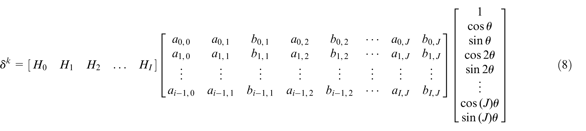
The matrix in the middle is the parametric matrix of the Hermite–Fourier polynomials. In this matrix,
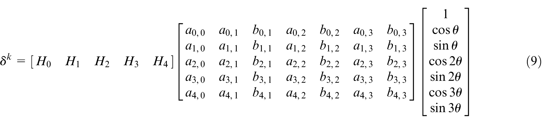
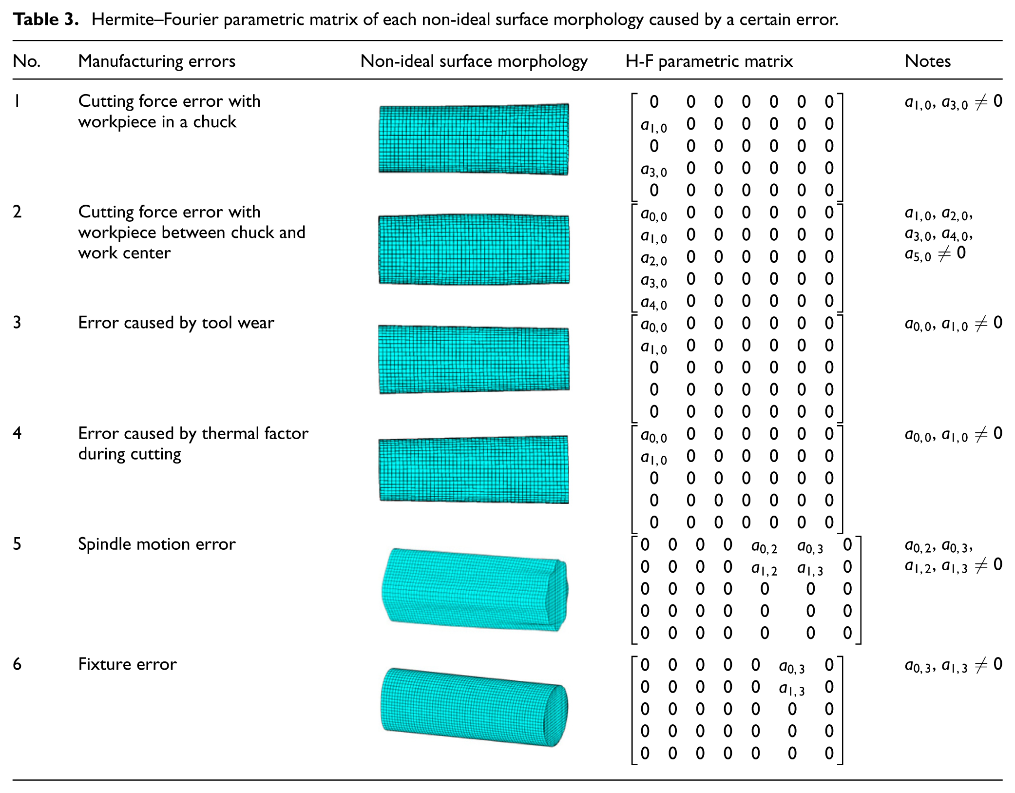
Table 3 summarizes the parametric matrix of each morphology caused by a certain manufacturing error. The parameters in the matrix are relevant to a certain morphology and are determined by the corresponding mathematical formulation in Table 2. The parameter values reflect the extent of variation of the morphology. Take the first manufacturing error in Table 3 as an example, according to the non-ideal surface morphology formulation defined in Tables 1 and 2, the deviation of the manufactured surface is only related to the third power of the distance between the cutting location and the spindle end. The parameter
Hermite–Fourier parametric matrix of each non-ideal surface morphology caused by a certain error.
Computing the total deviations for the non-ideal surface
The total deviations of the non-ideal surfaces are the consequence of various manufacturing errors. Each error plays a definite role in the manufacturing process. Considering the independence of the manufacturing errors during the manufacturing process, the total deviations of the manufactured surface can be regarded as the composition of the deviations caused by each error. With the unified expression of each non-ideal surface morphology, the superposition of multiple Hermite–Fourier polynomials is still a Hermite–Fourier polynomial. The total deviations of the manufactured surface can be considered as the superposition of corresponding parametric matrices. The expression of total deviations of a manufactured surface is given in Figure 6.
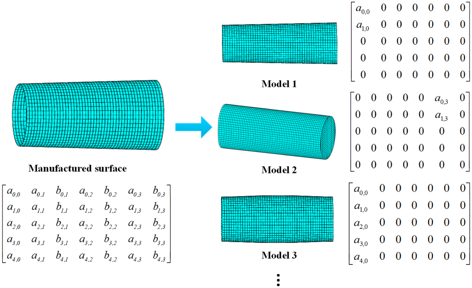
Expression of total deviations of a manufactured surface.
Figure 6 shows the manufactured surface affected by several errors, in which tool wear is the dominant factor, and the expression of the surface consists of Model 1, Model 2 and Model 3 and so on. Each model is a non-ideal surface morphology caused by a certain manufacturing error.
On account of the unified representation of each non-ideal surface morphology and the different levels of the impact caused by manufacturing errors, the manufactured surface can be modeled by the linear combination of the non-ideal surface morphologies by parametric matrices.
Verification of the representation method of non-ideal cylindrical surface
To verify the effectiveness of the representation method, a shaft-hole assembly is selected in the following case study. Using the Hermite–Fourier polynomials, several types of shaft-hole assemblies are modeled, then, sealing simulations and subsequent analysis are performed.
Three typical non-ideal long shaft cylindrical surfaces (taper, convex, concave) affected by three different primary manufacturing errors are chosen for sealing simulation. For taper surface, tool wear is the dominant error during manufacturing. For a low-rigidity workpiece clamped with a chuck and work center, the convex shape will appear under the effect of the cutting force, and the concave surface will be resulted from the vertical misalignment of chuck and work center. Models of these three features are shown in Figure 7.
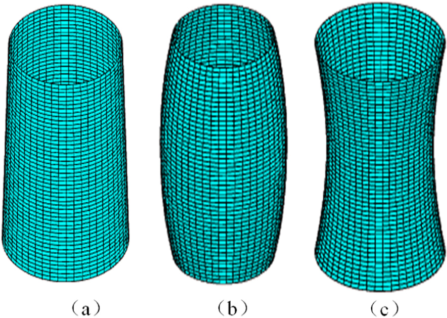
Three typical non-ideal surfaces in turning process: (a) taper, (b) convex and (c) concave.
With these three non-ideal shaft surfaces, the assembly structures composed of non-ideal long shafts and nominal holes are constructed. And the clearance fit is applied to these assemblies. Exemplary shaft-hole assemblies for sealing simulation analysis are given in Figure 8.
Example shaft-hole assemblies: (a) taper-ideal, (b) convex-ideal and (c) concave-ideal.
In Figure 8,
The long shaft-hole examples used in the sealing simulation and analysis consist of several non-ideal surface morphologies. The tapered shaft is affected mainly by cutting tool wear error, along with other two non-ideal cylindrical surface morphologies caused by cutting force and thermal effect. According to the mathematical formulations and parametric matrices listed in Tables 1–3, when
The preconditions are set for the simulation, in which the maximum dimension of shaft is 4.995 mm and
Parameter settings of the fluid in sealing simulation.
Comparison of leakage of different surface shapes.
From Figure 9, it should be noted that the leakage variation increases along with the increase in the form variation. The leakage variations are multitudinous because of the differences between surface shapes. By comparing the leakage of different surface shapes with same form variation, it can be concluded that the leakage of convex shaft is minimum, the leakage of taper shaft is larger than convex shaft and the leakage of concave shaft is maximum. The results also indicate that different non-ideal surface shapes that conform to the same tolerance zone have various effects on the functionality and performance of the product. Through this analysis, the validity of the representation method is verified by comparing the differences between these shafts applied in the sealing simulation.
When implanting multiple simulations, the non-ideal cylindrical surfaces need to be added in the simulation model continually; therefore, they should be sustained and generated rapidly. Since the non-ideal surfaces are caused by multiple manufacturing errors, the parametric matrices proposed in this article make it possible to consider each of the errors in the simulation. Moreover, the non-ideal surface can be easily obtained by changing the parameters in the parametric matrices when errors vary during manufacturing processes. The parameters in the matrix also represent different levels of effects of each error on the manufactured surface.
Unlike previous models established for analysis of product performance, the models developed by this representation method are based on non-ideal assemblies. To a large extent, the analysis results approximate the real conditions of the manufactured product. The representation method also facilitates the generation and application of non-ideal surfaces.
Conclusion
In this article, a novel representation method for non-ideal cylindrical surfaces is proposed and verified by the sealing simulation analysis of shaft-hole assemblies. A DCS has been developed to describe the deviations of the non-ideal cylindrical surface, which makes the description of deviations more simplified and effective.
A unified formula that combines Hermite polynomials and Fourier series is proposed, representing the deviations of the non-ideal cylindrical surfaces, which allows the unified expression of various deviation functions. Different non-ideal surface morphologies have their characteristic parameters, and these parameters can be conveniently expressed by a parametric matrix that is created from the expansion of the Hermite–Fourier polynomials. By changing the parameters, the non-ideal surface corresponding to specific manufacturing error can be generated conveniently. The proposed representation method facilitates modeling of the non-ideal cylindrical surfaces for simulation process, and other application cases.
This article provides a focused study limited to cylindrical surfaces and rigid parts. The ongoing extension of the proposed method is on planar surfaces and general surfaces. The main focus will be on the representation of a non-ideal surface under certain manufacturing process and the establishment of the corresponding DCS.
Footnotes
Declaration of conflicting interests
The author(s) declared no potential conflicts of interest with respect to the research, authorship and/or publication of this article.
Funding
The author(s) disclosed receipt of the following financial support for the research, authorship, and/or publication of this article: This work was supported by the National Science Foundation of China (Grant 51575031) and National High-Tech R&D Program of China (No. 2015AA043702). The authors would also like to thank Beijing Municipal Education Commission (Build a Project) for its support.