
Abstract
This article proposes a novel spatial parallel kinematic mechanism with three kinematic limbs and 4 degrees of freedom. Its mobile platform can realize two translations and two rotation movements. Of note is that this mechanism can realize flexible A-/B-axis rotation (rotations about the x- and y-axes) and the transformation between vertical machining mode and horizontal machining mode. Using Tilt and Torsion angle description method, the kinematics analysis of this parallel kinematic mechanism is carried out. On this basis, the geometrical parameters, including parameters of three limbs and mobile platform, are optimized. In view of the particularity of configuration, the limb in the postposition with two active inputs is analyzed first and then the remaining two identical limbs. In the optimal design, motion/force transmissibility is taken into consideration, and the local transmission index is used as the performance evaluation criterion to investigate the orientation capability of this parallel kinematic mechanism. Using performance atlases method, the optimal kinematic design of the 4-degree-of-freedom parallel kinematic mechanism is carried out and a set of preferable optimized parameters is obtained at last. By virtue of the kinematic advantages, the proposed parallel kinematic mechanism can be used as the modular machining unit in five-axis machine centers. Based on this work, a machine tool with high flexibility has been developed to process the five faces of a workpiece within one setup.
Introduction
Due to the increasing complexity of workpieces, high-performance five-axis machining equipments have now been widely used in manufacturing industry and meanwhile have been studied intensively for better performance. In the research field of five-axis machining equipments, hybrid (serial–parallel) machine tools have drawn more and more researchers’ attention.1,2 It is well known that the serial mechanisms usually have large workspace and simple kinematics but suffer from drawbacks like high inertia. In contrast, the parallel mechanisms have low inertia 3 and compact structures but suffer from limited workspace 4 and complex kinematics. 5 By means of rational design and optimization, hybrid machining tools can gather the merits of serial and parallel mechanisms and avoid their negative effects. Based on this idea, some models have already been developed and successfully applied in industry, such as Tricept, Exechon and Ecospeed.6–8
In some significant application fields, the workpieces are required to be high precision. So, installation accuracy, which has a great effect on machining accuracy and surface roughness, needs to be considered. One way to reduce the effect of installation on precision is to reduce the number of the installation process. So, five-face machining centers, which can machine five faces of the workpiece within one setup, avoid errors caused by multiple installations and have high practical value. 9 The function of five-face machining makes demands for high orientation capability of machine tools, and it also requires that the machine tools can realize transformation between vertical machining mode and horizontal machining mode in five-face machining processes with only one setup. Therefore, in machine tool industry, there is an urgent need for high flexible orientation capability and large rotation range (at least 90° in order to realize the function of five-face machining). The existing solution adopted by most five-axis machining centers is to distribute the large rotation range to A-/B-axis rotary tables and swinging heads. In other words, the large rotational range is realized by the coordination movement of rotary tables and swinging heads. However, this method brings difficulties to control. Besides, the rotation range of rotary tables is normally small and the whole rotation range is usually less than 90°. So, new mechanisms are in great need to fulfill the goal in another way. Due to the previously presented advantages and good potentials, parallel kinematic mechanisms (PKMs) with flexible orientation capability and large rotational range provide a promising solution. This article is an attempt to propose such a PKM and deals with its kinematic optimization.
Compared with the 6-DoF fully parallel mechanisms, lower mobility parallel mechanisms, whose DoFs are less than six, have lower kinematics coupling and less interference among limbs. 10 And in industry production, hybrid machining tools based on lower mobility parallel mechanisms (usually 3-DoF parallel tool heads) have been already applied. 11 Tricept hybrid robot is such a successful application, obtaining nearly 70% of the parallel equipments’ market. 3 As Dr Neumann, 12 the inventor of Tricept, said, the success of this hybrid mechanism was owed to the 3UPS-UP (U: universal joint; P: prismatic joint; S: spherical joint) low-mobility parallel mechanism, which has fewer joints and less inefficient degrees of freedom. The reasons why the parallel mechanisms are hardly used in industry are none other than their complex structures and the resulting high kinematic, dynamic coupling and manufacturing difficulty. 13 However, only few fully parallel 5-DoF mechanisms have been currently applied in industry production, such as series of fully parallel mechanisms developed by METROM. 14 On the whole, the most popular parallel mechanisms in practice are those having simple joint configurations or (partly) symmetrical structures.
For the application of PKMs in manufacturing field, higher orientation capability and simpler kinematics are usually expected. Among the researches of hybrid/parallel mechanisms, one of the most important concerns is the high orientation capability.15–17 Tricept machine tools have a serial A/C-axis (rotations about the x- and z-axes) tool head, leading to high rotational output and large workspace. 18 However, the traditional serial A-/B-axis tool heads have drawbacks like complicated transmission system, huge structure, hard to install and hard to maintain. And in practical engineering application, serial architecture brings difficulties to locus planning and control because its two rotations are not coupled motions. 19 Moreover, the finished surface is sometimes scratched by the rotating cutter during setup when using a serial articulated tool head. 20 By contrast, Ecospeed machining centers, developed by German DS-Technology, 20 can realize the function of the A-/B-axis rotation (rotations about the x- and y-axes) with a 3-PRS parallel module, which offers one translation degree of freedom and two rotational degrees of freedom, and avoids the drawbacks of serial A/C-tool head. 21 Besides, the parallel machine module has an advantage in the flexibility of orientation over its serial counterpart. And flexible orientation capability offers the possibility of manufacturing complex freeform surfaces, such as surfaces of large-scale aircraft structure parts. For industry applications, the orientation output capability is supposed to be more than 40°. 20 In view of this, the orientation capability of the 4-DoF spatial parallel mechanism proposed in this article is investigated and it is also the main target to be optimized in order to get better performance in practical applications.
Sequentially, kinematic optimization with the goal of high orientation output should be carried out to derive the parameters of the discussed mechanism. As the precondition of dimension synthesis, performance evaluation is of vital importance, in which the performances to be evaluated and the method of executing evaluation process are the main concerns. 22 Parallel manipulators have advantages in motion/force transmission. Thus, the performance index based on motion/force transmission is supposed to be taken into consideration in the design process of a certain PKM. 23 On the basis of the transmission angle, a local transmission index (LTI) was proposed in Wang et al. 24 to evaluate the motion/force transmissibility of PKMs. Using this performance evaluation index and its extending indices, the optimal kinematic design of the proposed 4-DoF PKM is carried out.
The remainder of this article is organized as follows. In section “Architecture description,” the proposed PKM is presented in detail and its mobility is analyzed. In section “Inverse kinematics analysis,” the inverse kinematics of this parallel mechanism is derived. Section “Optimal design” introduces the performance evaluation criterion which takes the orientation capability into consideration first. And on this basis, the optimization process is carried out, mainly considering its flexibility of A-/B-axis rotations and its capability to transform between vertical machining mode and horizontal machining mode. Section “Conclusion” concludes this article.
Architecture description
The CAD model and kinematic scheme of the novel 4-DoF parallel robot are shown in Figure 1. The parallel tool head has two translational and two rotational (2T2R) degrees of freedom. In order to gain high orientation capability, A-/B-axis rotational angles should be larger than 40°. 20 Besides, to machine the five faces of workpieces within one setup, the hybrid machine tool is supposed to realize the transformation between a vertical machining center and a horizontal one. To reach this goal, this article mainly investigates the orientation capability of this parallel module.
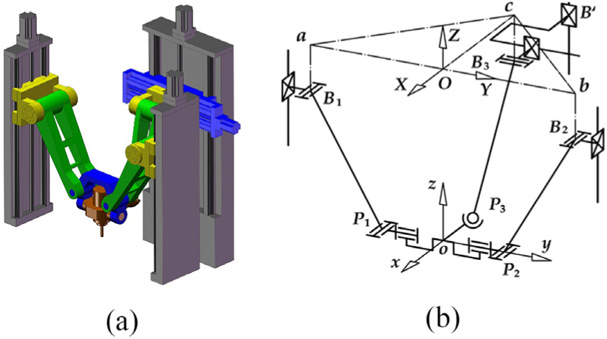
A novel spatial 4-DoF parallel mechanism: (a) CAD model and (b) kinematic scheme.
The global frame
Except for offering an additional degree of freedom than normal 3-DoF head-tools, this mechanism can eliminate the influence of parasitic motion along the Y-axis. When unwanted motion along the Y-axis occurs with the rotation of platform, it can be compensated by the active motion of the platform. 25
As a result of two PRU kinematic limbs, the translation of the moving platform along the X-axis is restricted. So, there is no parasitic motion along the X-axis. As the third PPRS limb has six DoFs, the connection line
A potential application of this 4-DoF parallel mechanism is illustrated in Figure 2, which is a hybrid five-axis machining center. Apart from the parallel mechanism 3, this hybrid machining center has three serial parts, which are a moving slide along the x-axis 5, a moving slide along the y-axis 2 and a rotary table about the z-axis 4. The two slides, which make up a X-Y table, extend the stroke of parallel mechanism. The rotary table assists the realization of five-face machining.
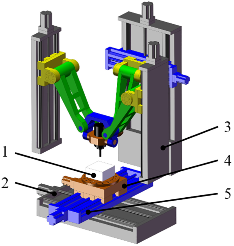
Hybrid machine tool with 4-DoF PKM: (1) workpiece, (2) moving slide along the y-axis, (3) proposed PKM, (4) rotary table about the z-axis and (5) moving slide along the x-axis.
This mechanism has large A-/B-axis rotation angle and can realize function of five-face machining. The implementation of five-face machining is like follows: when the moving platform is in its zero position, the machining center is in vertical machining mode and the upper surface of the workpiece 1 can be machined. After completion in upper surface machining, the moving platform rotates 90° about the y-axis and the machining center is in the horizontal machining mode. Cooperating with the rotary table, four vertical faces of the workpiece can be machined. In a word, the hybrid machining center can realize five-face machining in one setup and has a promising application prospect.
Inverse kinematics analysis
As shown in Figure 1(b), vertices of the platform are denoted as joints
As the description in section “Architecture description,”P1 and P2 are constrained within the
The geometrical parameters are denoted as follows,

In all, parameters


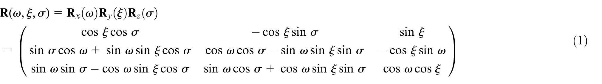
Multiplied by the coordinate rotation matrix

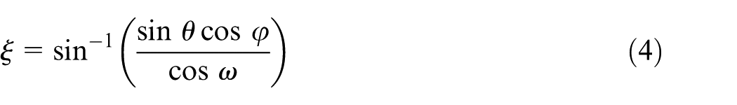
where by definition,
The coordinates of revolute joints centers under global frame are


where by definition,
The constraint in the third branch denotes that slide B3 and joint P3 have the same y-axis coordinate. Besides, the mechanism offers the constraints
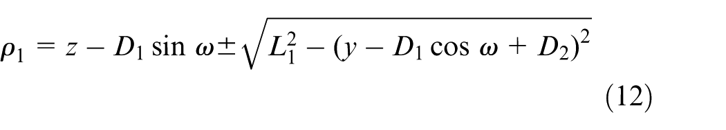


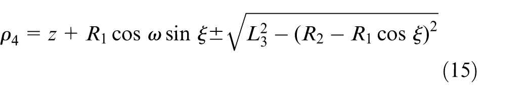
For the presented configuration of the mechanism in Figure 1, the sign “+” in equations (12)–(15) is taken here.
Optimal design
In the optimal design, flexible orientation capability is the general objective. It is further reflected in two aspects: capacity for flexible A-/B-axis rotation and the ability to realize the transformation between vertical machining mode and horizontal machining mode. The performance-chart-based optimal design method 26 is used here since it provides all possible solutions instead of single one.
In the optimization process, each limb of the 4-DoF parallel mechanism has three parameters to be considered. They are the length of the limb, the distance between the central point of the moving platform and the contact point and the distance between the central point and the vertical slide axis. For PPRS limb, geometrical parameters to be optimized are
To gain more reasonable results, the optimization process is divided into two parts. The PPRS limb in postposition is optimized first due to its special configuration, and then, the geometrical parameter optimization of the other two PRU limbs is carried out with the parameters derived from the first step.
The distributed process has the advantage of considering the orientation capabilities of different limbs over that assuming all limbs have identical parameters. Before the kinematic optimization design, geometric parameters should be normalized. Since the six parameters
Let
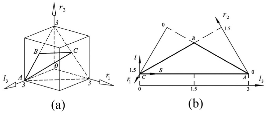
Parameter design space: (a) spatial description and (b) planar description.
The mapping functions between

or


In order to investigate the orientation capability of the proposed mechanisms, the motion/force transmission performance is taken into consideration in the optimization process. With screw theory 19 as the mathematic foundation, the orientation capability investigation and optimal design process based on the existing Local Transmission Index 23 are carried out. And the results are shown using performance chart–based design methodology. 19
Orientation capability analysis and optimal design of the PPRS limb
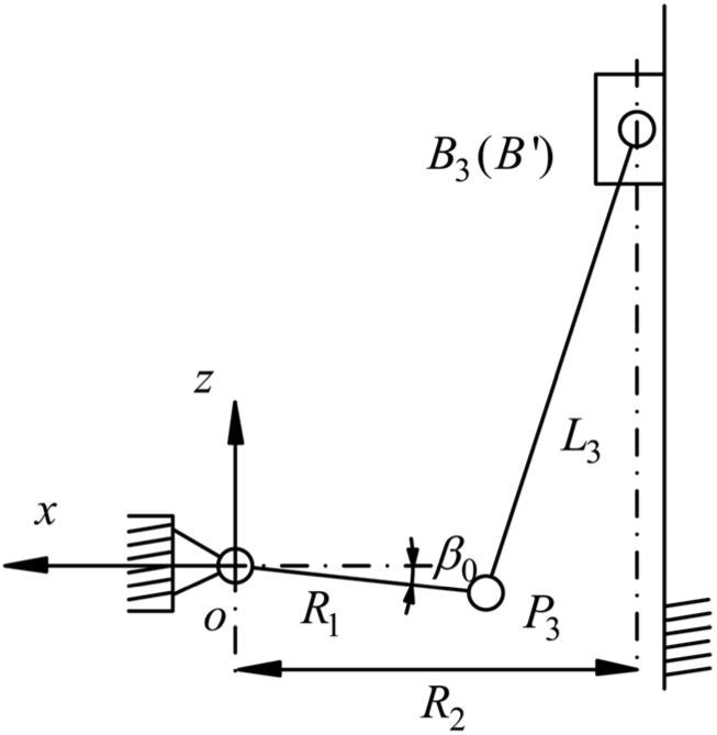
The separate optimization of the postposition, PPRS limb is equal to the optimization of a spatial four-bar mechanism with two inputs and two outputs. The kinematic scheme is shown in Figure 4. In view of practical requirements, the individual limb is supposed to realize flexible A-/B-axis rotation and the maximum of rotation about the y-axis needs to be more than 90°.
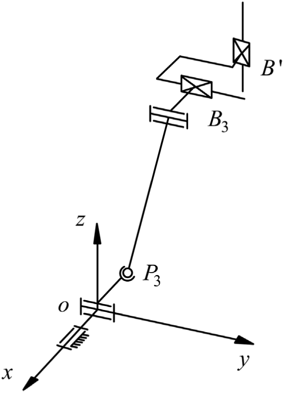
Equivalent model of the PPRS limb.
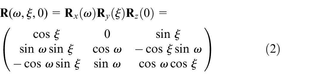
The parameters used to describe the orientation of this spatial four-bar mechanism are
The inverse kinematic analysis is similar to the results in section “Inverse kinematics analysis.” The position of the actuator

The unit input twist screws of the two actuators can be expressed as


And the transmission wrench screws can be derived by the method in Sun et al. 23 as


where by definition,
And unit output twist screws
According to the definitions, the input transmission index (ITI) of PPRS limb can be expressed as
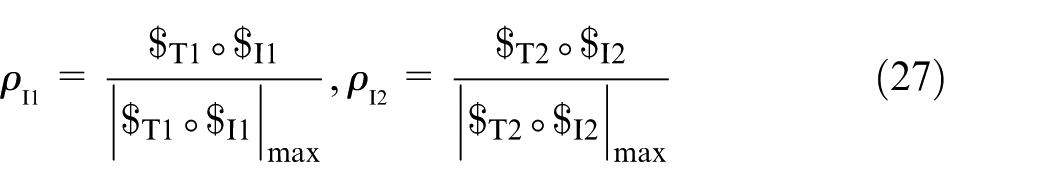
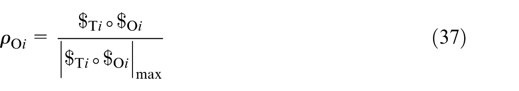
And the output transmission index (OTI) of PPRS limb can be expressed as
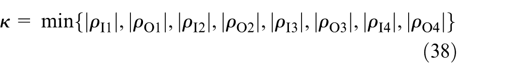
Consequently, the local transmission index (LTI) of the PPRS limb can be defined as

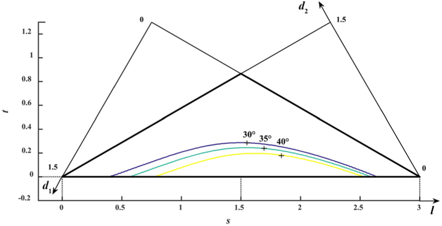
Based on this index, a good transmission workspace (GTW) under the description of T&T angles

First, let
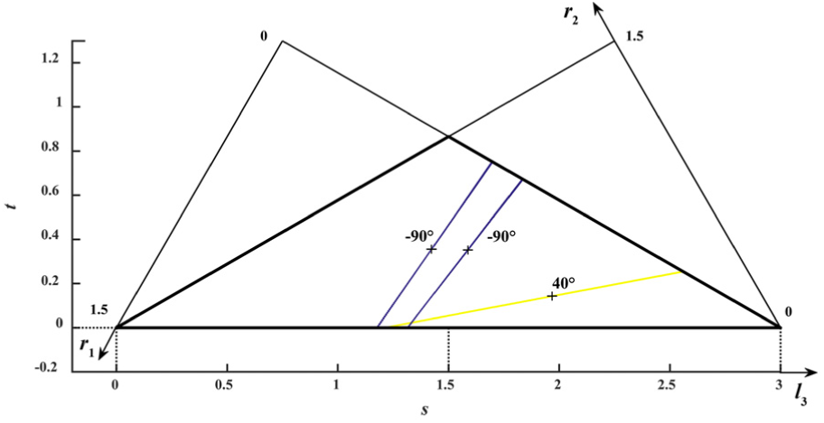
Atlas of the
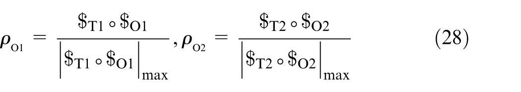
In order to realize the transformation between a vertical machining mode and a horizontal machining mode, the rotation angle about the y-axis from the origin posture should be as far as 90° when
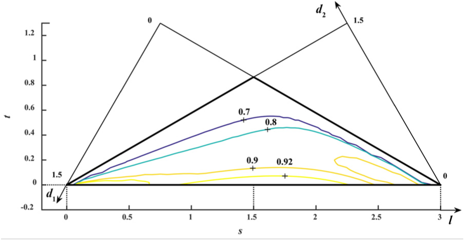
Atlas of the
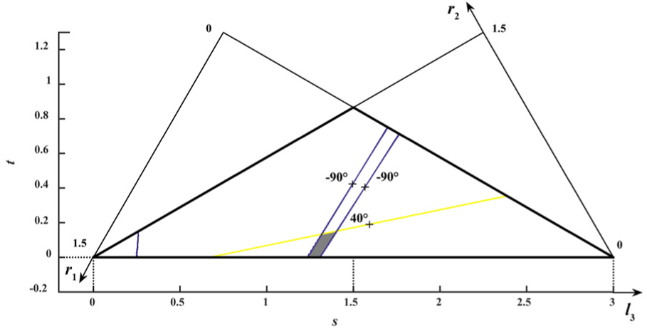
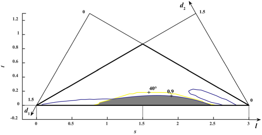
A combination of criteria
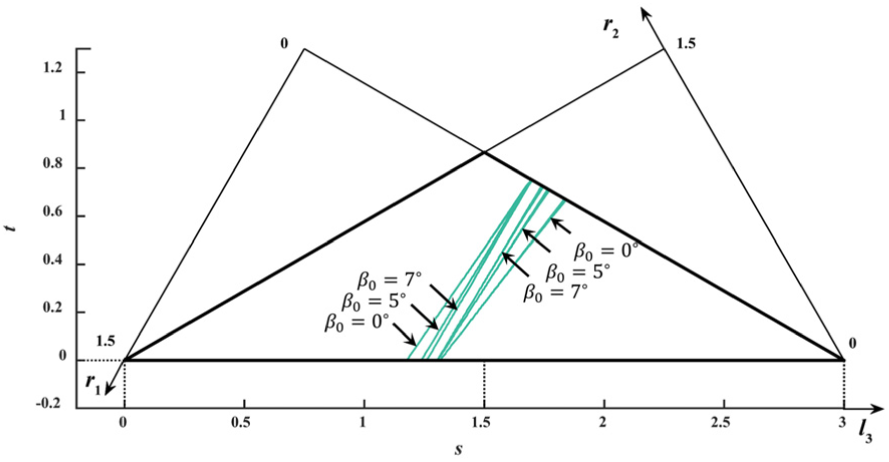
Optimum region for the parameters of the PPRS limb (considering
One solution is to reduce the constraint to
Schematic diagram of the fixed attitude angle of the moving platform
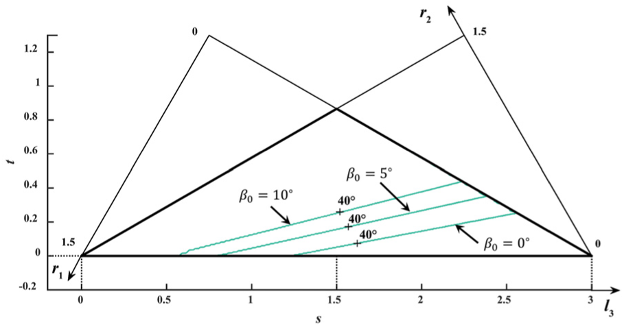
Different optimum region meeting constraint
With
Optimum region for the parameters of the PPRS limb with
Orientation capability analysis and optimal design of the two PRU limbs
After optimization in the previous section, a reasonable set of geometrical parameters of PPRS limb has been derived. Based on this result, kinematic optimization of the whole mechanism is carried out.
The parameter normalization process of the two PRU limbs is the same as the postposition PPRS limb. Normalization of the geometric parameters of the other two PRU limbs
Besides GTOC, a new evaluation criterion named global transmission index (GTI) is used to investigate global motion/force transmission performance over the derived GTW. It is defined as
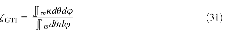
In view of mechanism symmetry,
On account of four translational actuators, there are four unit input twist screws in all, which can be expressed as


The transmission wrench screws
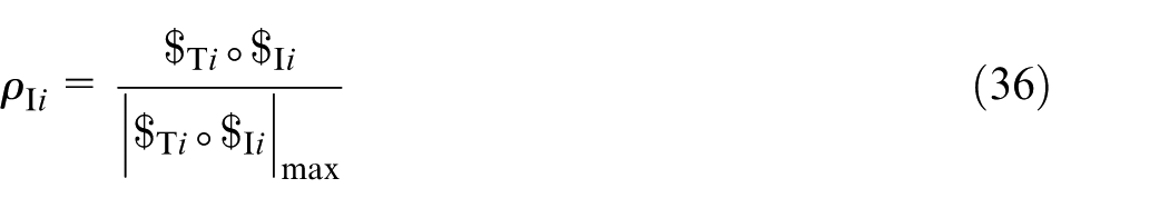
The criterion LTI
Based on the definitions, the performance atlases of
Atlas of the
Atlas of the
By constraining
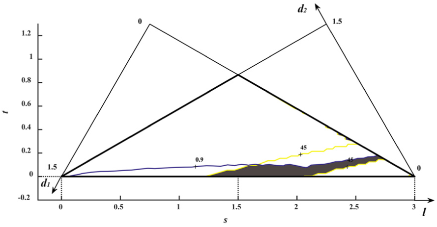
Optimum region for the parameters of whole parallel mechanism (considering
So far, all normalized geometrical parameters of each limb have been derived:
The provided geometric parameters are normalized and the orientation capability of the mechanism is only related to the ratio of this parameters. In practical application, the derived parameters should be multiplied by a scale factor D to derive the actual parameters, and the factor D is determined by the specific application requirements, namely, stroke. Take a potential application as an example: the scale factor D is set as 1000 mm, and the geometrical parameters with dimension are derived as
On this basis, the GTW is investigated. With the lateral displacement
Good transmission workspace when
Of note is that transformation function (i.e. vertical to horizontal) of this parallel mechanism is a big restriction on the parameter selection range in the design process. As shown in Figure 15, the constraint
Different optimum region meeting constraint
Optimum region when the constraint is only large
Good transmission workspace when the constraint is only large
Prototype development
Based on the optimal design results and the concept presented in Figure 2, a prototype as illustrated in Figure 18(a) and (b) has been developed. As previously analyzed, the parallel model can realize the vertical–horizontal transformation as shown in Figure 18(c). On this basis, cooperating with a slider and a rotary table with continuous rotation capability, the developed machine is capable of five-face machining with single setup procedure. This is very helpful to the improvement of machining accuracy and orientation flexibility. The machine developed here has promising prospect in the process of structural components with freeform surfaces.
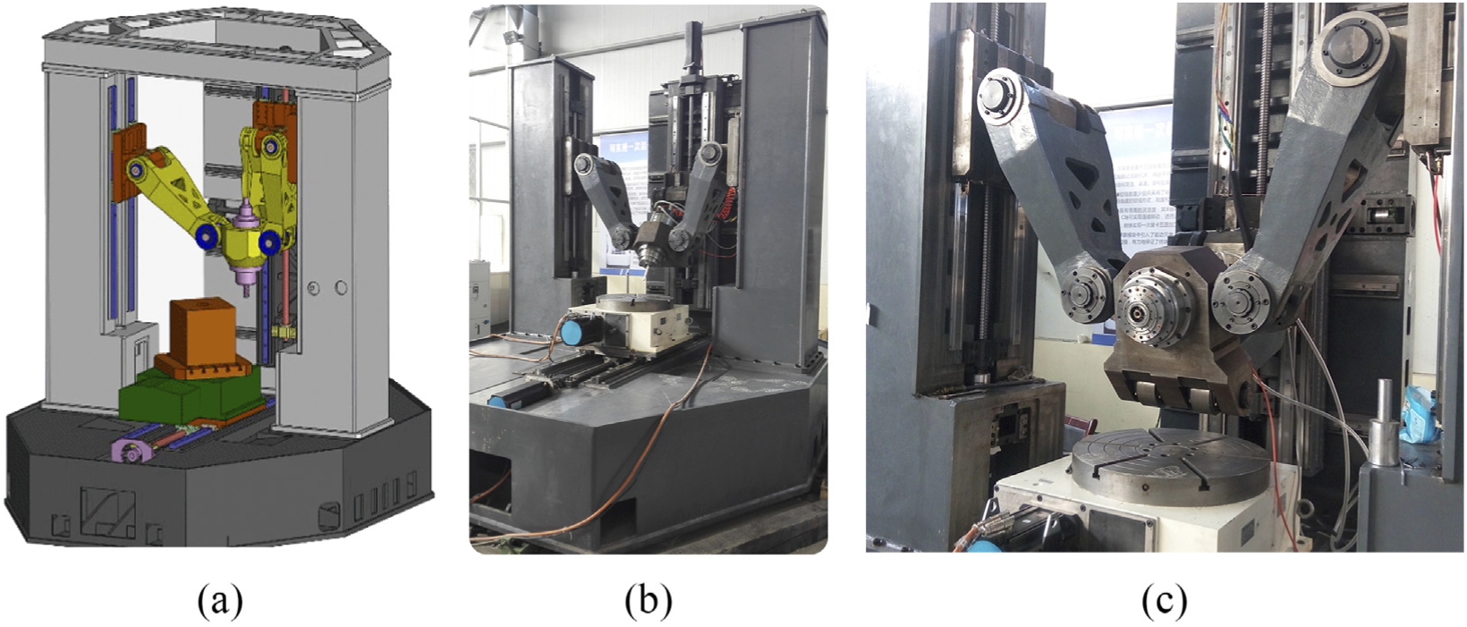
Developed prototype: (a) CAD model, (b) overview and (c) vertical–horizontal transformation.
Conclusion
In this article, a novel 4-DoF parallel tool head is proposed based on practical demands and a set of optimized geometrical parameters has been obtained by considering the motion/force transmission performance. The main goal of optimization is to realize the function of flexible A-/B-axis rotations and the transformation between vertical machining mode and horizontal machining mode. Instead of assuming that three limbs have identical geometrical parameters, the optimization process is carried out in two steps. The PPRS limb in postposition is optimized first aiming at achieving flexible orientation capability and a large rotation range. Then, the whole parallel mechanism is analyzed and optimized. Besides, with the orientation description method of T&T angles, GTOC is derived and the effect of lateral displacement of moving platform on orientation capability has also been investigated. Optimization result obtained in the last section enables this 4-DoF parallel mechanism to fulfill the optimization goals and a prototype with high flexibility has been developed based on the work presented in this article. By virtue of flexible orientation capability and transformation function, the novel machining center can machine five faces of workpieces within one setup. And high machining precision and high working efficiency are possible to be achieved.
Footnotes
Appendix 1
Declaration of conflicting interests
The author(s) declared no potential conflicts of interest with respect to the research, authorship and/or publication of this article.
Funding
The author(s) disclosed receipt of the following financial support for the research, authorship, and/or publication of this article: This work was supported by the National Natural Science Foundation of China under Grants 51675290 and 51425501. The second author (F.G. Xie) received the support from the Alexander von Humboldt (AvH) Foundation.