
Abstract
True application of ultrasonic vibrations improves the solid-state process of friction stir welding. This study focuses experimentally on the effects of axial (along the tool axis) and bending ultrasonic vibrations on material stirring process of friction stir welding process. First, in ABAQUS software, an especial friction stir welding tool set geometry was designed containing two types of axial and bending vibrations in different frequencies. Resonance frequency of the tool set, in axial and bending modes, occurred at 19.8 and 23.8 kHz, respectively. The use of a unique set of friction stir welding insert tools as well as its ultrasonic transducer which was equipped with half-ring piezoelectric actuators, due to the identical tool set inertia, made the comparison of the ultrasonic vibrations in different modes to become possible. Then, the tool was manufactured and some experiments were designed to join aluminum 6061-T6 plates as working material. Finally, to investigate the effects of vibrations on the quality of the weld, hardness, tensile strength, temperature and axial force were measured. Regarding the obtained results, in spite of welds, which were created with axial vibrational mode and without vibration states, superimposing bending vibrations, because of its better capability of material stirring pattern, resulted in a higher weld quality, whereas the tool axial forces were enlarged.
Introduction
In recent years, superimposed ultrasonic vibrations to fiction stir welding (UaFSW) process have been noticed drastically due to its advantages. Suitable superimposed ultrasonic energy to the friction stir welding (FSW) process facilitates material flow, enlarges temperature distribution and improves welding sub grain refinement.1–7
Ruilin et al. numerically studied the temperature field of UaFSW for Al 2024 plates with thickness of 1.8 mm. Longitudinal vibrations along the tool axis were implemented. Ultrasonic vibration was considered as an extra inertia force (F 2), added to general FSW force (F 1) without vibration. The resultant of the mentioned forces affects thermal energy and therefore temperature distribution. Results showed that due to additional heat input, generated by ultrasonic vibration, the weld nugget zone enlarges. The other outcome of this study was the effect of superimposing ultrasonic vibration which is capable to hasten FSW process, since it can enhance material flow which is suited for higher welding feed rates. 1 Also, some researchers studied the effects of ultrasonic vibrations on friction stir spot welding (FSSW) process.8–11 Results indicated that superimposed ultrasonic vibrations in FSSW process had the same advantages mentioned above for UaFSW process.
Experimental investigation about the effects of longitudinal ultrasonic vibrations along tool axis on FSW process was conducted by Amini et al. An ultrasonic transducer with resonance frequency of 20,347 Hz in axial mode was designed and manufactured. Results indicated that superimposed axial vibrations in UaFSW caused an increase in the tool tip temperature, whereas maximum axial force decreases about 25% in comparison with the state of without vibration. Facilitation of material flow, because of better working material stirring in UaFSW process, was reported as the reason for weld temperature increase. 2
Mathematical model of UaFSW process was developed by Shi et al. They studied the effects of axial ultrasonic vibrations on heat generation and material flow. Results of their study were compared with numerical simulation using Fluent software and with experimental efforts on Al6061-T6 plates. Vibrations were superimposed using inclined sonotrode with the angle of 40° with respect to the horizontal axis and distance of 20 mm in front of FSW tool axis. The article outcomes were as follows: (1) enhanced plastic material flow around the tool in UaFSW and (2) reduction of contact shear stress at tool-work piece interfaces. The rate of frictional heat generated by ultrasonic vibrations (qh ) at contact interface of working material and sonotrode was obtained as relation (1), which is insignificant 12
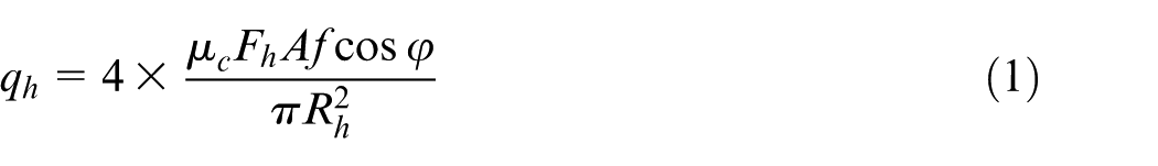
where μc
is the interface friction coefficient and Fh
is the sonotrode clamping force. Also, A and f are amplitude and frequency of vibrations, respectively. Eventually,
The other important consequence of the study was considerable effect of ultrasonic vibration on material softening in comparison with its thermal effect. Also, results reported that the better material flow led to minimize welding defects. 12
Similarly, an experimental UaFSW investigation was performed on aluminum alloy (2A12-T4) by Liu and Wu. Ultrasonic axial vibrations were superimposed separately 20 mm in front of FSW tool using a sonotrode. Material flow was visualized using special marker at tool–workpiece interfaces. Results revealed that, for UaFSW samples in contrast to FSW samples, more uniform variations of material velocity profile, adjoining to the tool pin, were observed. 4
Experimental investigation about the effects of axial ultrasonic vibrations on FSSW of Al6061 plates was conducted by Rostamiyan et al. Process parameters such as tool rotary speed, dwell time and plunge depth along with and without vibrations were optimized through Taguchi design of experiments (DOEs) method. Results indicated that applying 1200-r/min tool rotary speed, 6-mm plunge depth and 6-s dwell time along with vibrations brings about maximum hardness and optimum lap shear force. 13
In another study, optimal joint strength of plastic plates which were welded through UaFSW process was obtained with hybrid technique of artificial neural network (ANN) and genetic algorithm. 14
Finally, the authors of this study, during their previous investigation on UaFSW process, showed that superimposed ultrasonic vibrations in bending mode on FSW process is possible. 3 In this regard, a tool set (transducer along with FSW tool) was designed, which was actuated by a set of half-ring piezoelectric actuators. Results indicated that applying bending vibrations improves FSW process outputs such as tool axial welding force and temperature distribution.
This study focuses experimentally on the effects of superimposed ultrasonic vibrations in bending and axial modes on weld quality of aluminum 6061-T6 plates and output UaFSW process parameters. According to above articles, superimposed ultrasonic vibrations on FSW process have been done in different methods. But in order to choose the most applicable method of applying vibrations in industry, making a proper comparison of applying vibrations to FSW process with the mentioned methods is required, which has not been accomplished so far. This study experimentally compares the effects of superimposed ultrasonic vibration-assisted FSW process in axial and bending modes on weld quality and output UaFSW process parameters. The comparison could be achieved through using two following approaches:
Approach 1 indicates the design of two separate tools and transducers, where each one vibrates at an identical resonance frequency (e.g. 20 kHz), the one in axial mode and the other one in bending. Choosing this approach brings about geometrical and dimensional variations in the tool sets and therefore variations in mass of the tool sets and accordingly inertia of them are inevitable. Regarding the high velocity variations of tool sets in ultrasonic vibrations, dissimilar masses of tool sets lead to a huge difference in their inertia and consequently the applied ultrasonic energy to the weld zone. So, utilizing this approach for making a proper comparison is not suitable.
Approach 2, which was used in this study, suggests complicated and innovative design for just one set of tool and transducer. The tool set is capable of vibrating in both axial and bending modes with dissimilar frequencies but not far from each other. Utilizing this approach is based on one assumption which implies the effect of almost 3-kHz frequency differences on results of experiments in contrast to inertia differences mentioned in Approach 1 is negligible.
Therefore, a unique UaFSW tool set was designed to have both axial and bending mode in different resonance frequencies. To evaluate the effects of these vibrational modes, some experiments have been conducted and several UaFSW output parameters such as uniaxial tensile test of welded specimens, microhardness profile of the weld cross section for some welded samples, tool axial force and temperature of the UaFSW tool shoulder edge were measured. Also, in order to investigate the effects of tool rotational speed, welding feed rate and variation types (axial, bending and the state of without vibration) on UaFSW process, a table of full factorial DOEs was used.
Tool set design
As described earlier, what is special about this study is design of unique UaFSW tool set (transducer along with FSW tool) geometry, which is capable of vibrating in two axial and bending frequency modes, separately. The mentioned tool set is able to make correct comparison of the effects of applying bending and axial modes on FSW process. Figure 1 illustrates procedures of manufacturing final ultrasonic-assisted FSW tool and transducer.
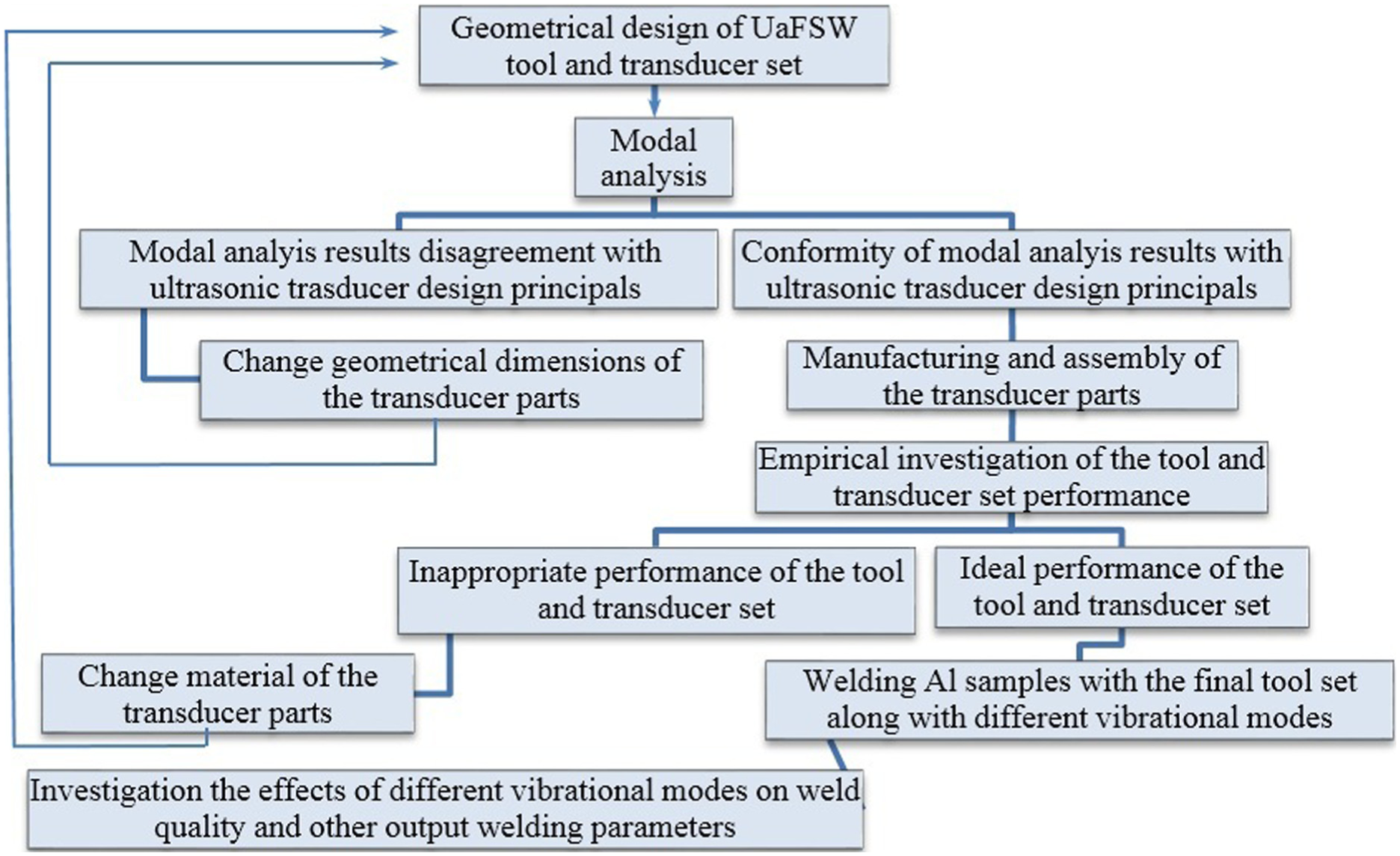
Procedures of manufacturing final UaFSW tool and transducer set.
To do so, as shown in Figure 2(a), four pairs of half-ring piezoelectric actuators were used. The full rings of the actuators were cut by water jet process. Attempts for the cutting with laser, wire cut and the other mechanical processes were not successful. In bending mode, exertion of AC electrical signals with 180° phase difference to any half pairs of piezoelectric actuators causes, while one set of half rings is in tension, the other set bears compression (Figure 2(b)). Also, in axial mode, both halves of piezoelectric actuators are actuated electrically, with no phase difference (Figure 2(c)).
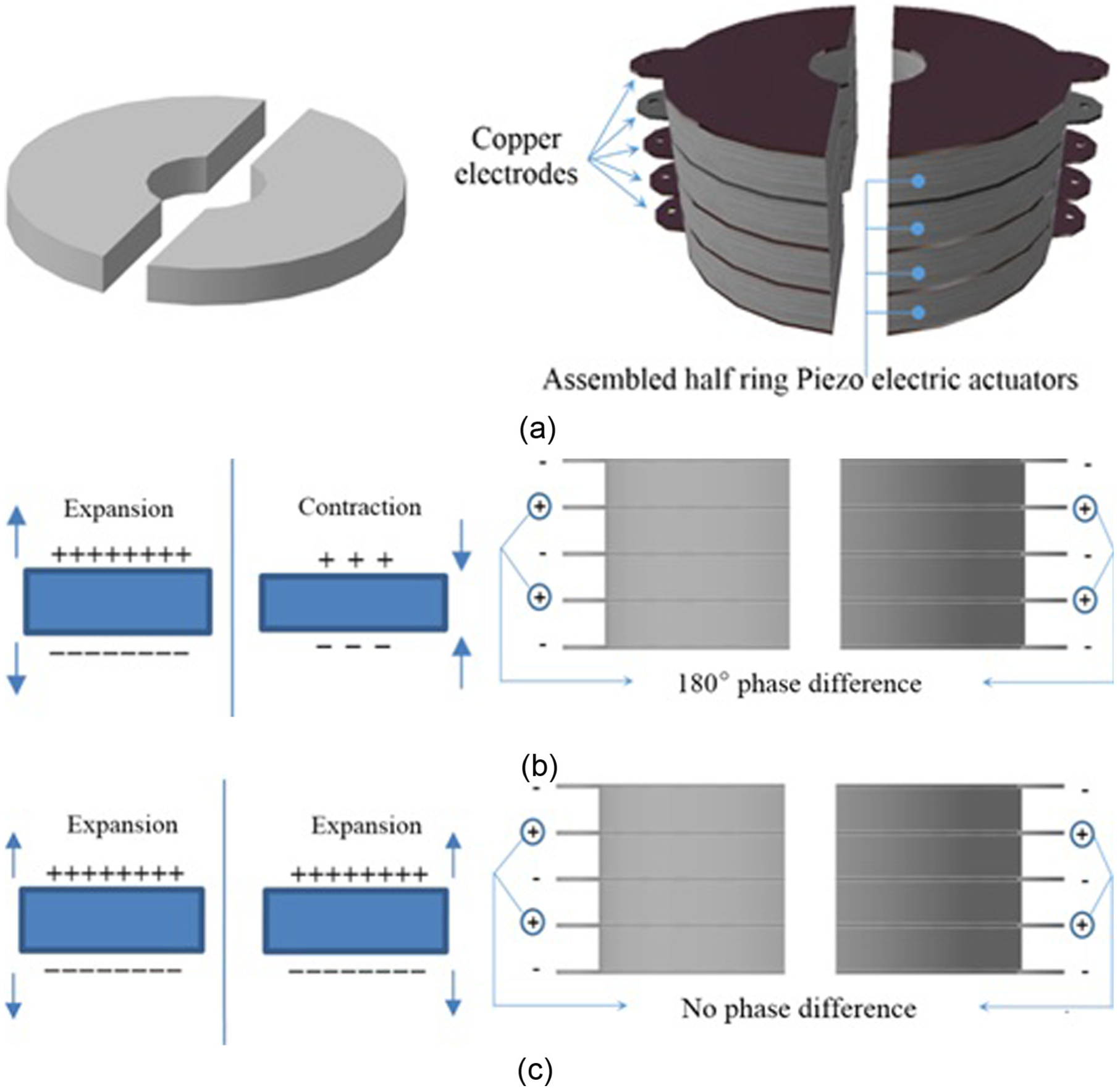
(a) Schematic assembly of half-ring piezoelectric actuators, (b) 180° phase difference in bending mode and (c) no phase difference in axial mode.
Figure 3 shows the design of a transformer (Design and Manufacturing, University of Kashan) which is capable to produce two AC outputs with 180° phase difference from one AC input.
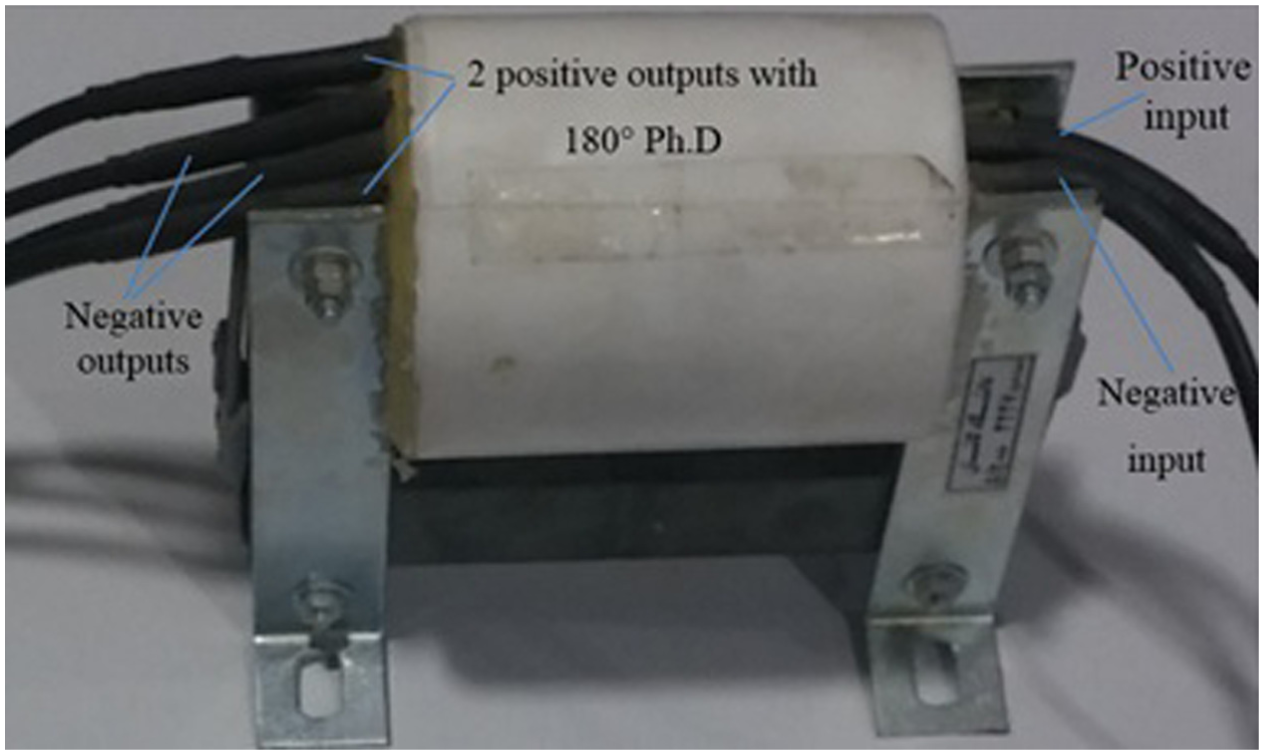
Transformer used to produce two AC outputs with 180° phase difference.
In axial mode, two half-ring sets were actuated without any phase difference. In this regard, without using the transformer, all the positive and negative poles of actuators in both half-ring sets were connected to the positive and negative outputs of Miodrag Prokic Interconsulting Co. (MPI) ultrasonic generator, respectively.
Tool set design constraints
Following considerations were implemented to tool set design:2,3,15,16
Vibrational node should be placed in tool flange where the tool set is clamped from.
The position of the tool flange should be identical for both axial and bending modes.
Distance between tool set tip and middle of piezoelectrics should be multiplier of λ/4.
Maximum ultrasonic horn diameter should be smaller than λ/4.
Tool set tip should be placed in maximum amplitude (antinode) for the both vibrational modes.
Tool set dimensions should be chosen such a way that not only the two resonance frequencies should be near to 20 kHz but also there should be suitable frequency difference between the mentioned frequencies and other undesirable resonance frequencies.
According to above considerations, various tool sets with different geometry dimensions were designed and numerically simulated through CATIA and ABAQUS software, respectively. Figure 4(a) and (b) shows the models of assembled tool set geometry and its tubular holder.
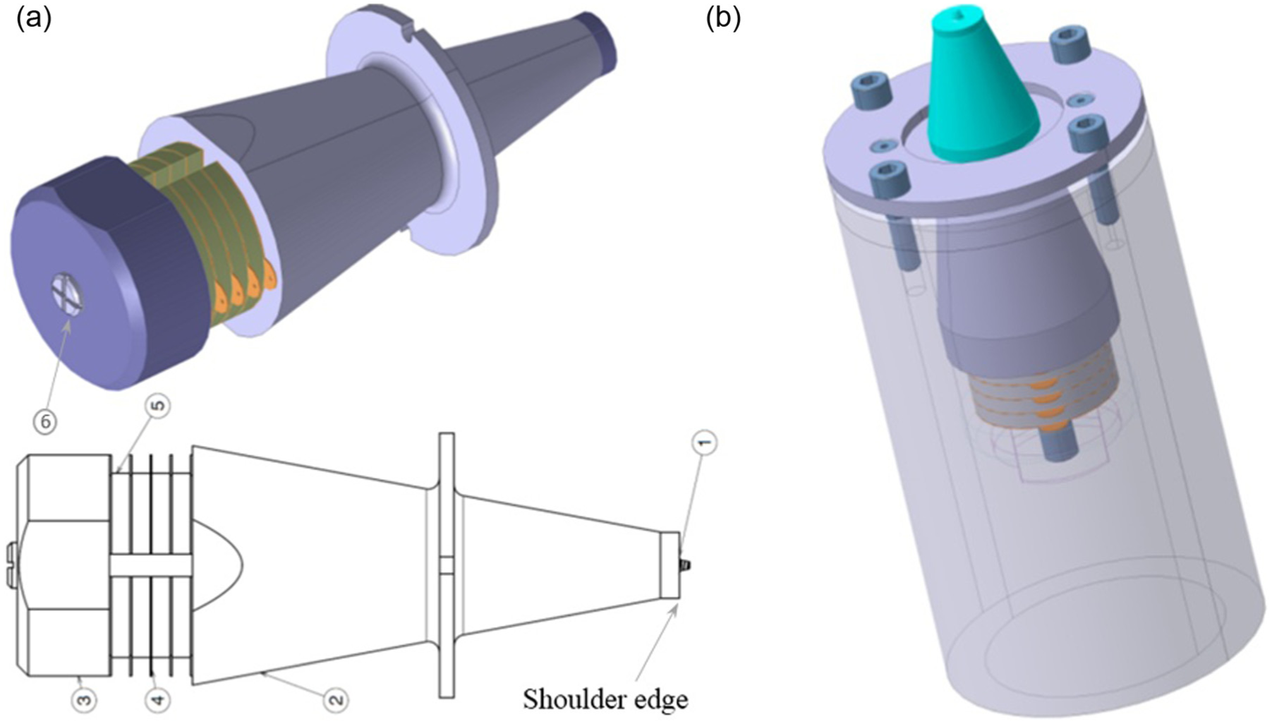
(a) Final tool set geometry and (b) tool set holder.
The modal analysis results of the mentioned model in Figure 4(a) illustrates axial and bending modes occurred at frequencies of 18,300 and 23,300 Hz, respectively. Figure 5(a)–(c) correspondingly demonstrates finite element method (FEM) results of modal analysis in three conditions of without, axial and bending vibrations.
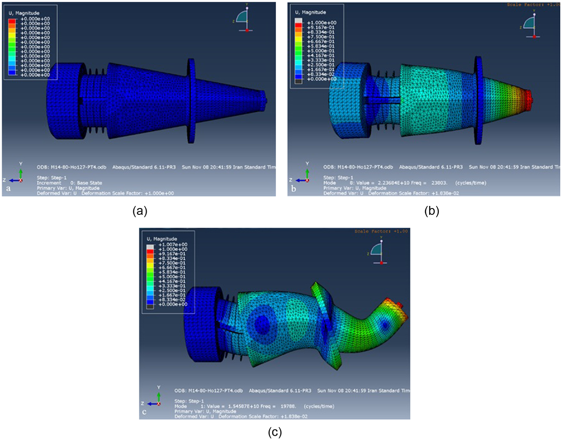
Frequency modal analysis in three conditions: (a) without, (b) axial and (c) bending vibrations.
Modal analysis
To modal analysis of the tool set, each of the tool set CATIA models were entered into ABAQUS software. In Property module, according to Table 1 data, material properties of each part were specified and allocated to its corresponding part model.
Material properties of the tool set parts.
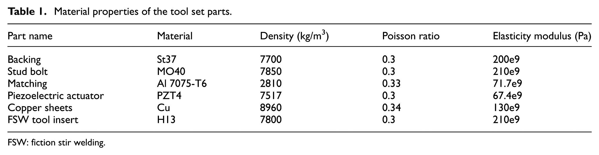
FSW: fiction stir welding.
In Assembly environment, parts were inserted separately and independently from the backing (tool set end) to the FSW tool insert (tool set tip). Then, in Step module, frequency analysis range was chosen 18–24 kHz. In Interaction environment, all the contact surfaces were attached to each other with tie constraint, from end to tip of the tool set. Finally, in Mesh module, standard three-dimensional (3D) stress—Tetra mesh was used for the whole parts.
Study of the frequency analysis simulation of several models (with different dimensions and various material types of the tool set parts and so on) led to a final UaFSW tool set geometry capable of vibrating in axial and bending modes at 18,300 and 23,300 Hz, respectively, which is shown in Figure 4(a).
Geometry of the FSW tool insert
The FSW tool insert geometry was selected according to Arora et al. 17 and Elangovan and Balasubramanian’s 18 research. In this regard, a tapered cylindrical pin geometry was selected, with 2.8-mm length, top and bottom diameter of 4.5 and 3.5 mm, respectively. Also, shoulder diameter of 18 mm with a conical concave-shaped bottom angle of 2° was chosen.17–19
Manufacturing of UaFSW tool set
Figure 6(a) shows all manufactured separated parts of the final tool set. The piezoelectric actuators and Cu electrode sheets with thickness of 5 and 0.5 mm, respectively, were cut by water jet machine. The whole contact surfaces were ground and polished by fine mesh sandpapers. Figure 6(b) shows the assembled tool set clamped in a pair of steel flanges. The flanges were used to fasten the tool set in lathe chuck.
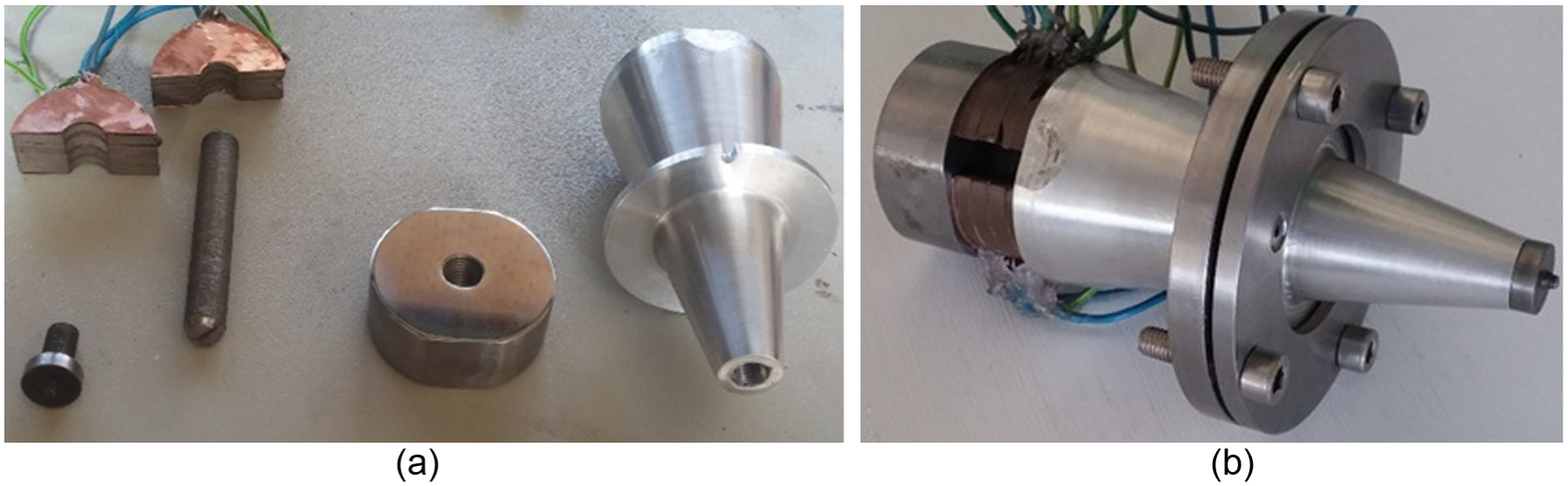
(a) Detached tool set parts and (b) assembled UaFSW tool set along with the flange.
Measurement of axial and bending vibration amplitudes
In order to measuring amplitude of vibrations in axial and bending modes, according to Figure 7(a), gap sensors with model number of PU-02A, which is a type of proximity sensors with 1-μm resolution, was used. Also, AEC-5502A-01 converter was applied to convert tool tip displacements into electrical signals.
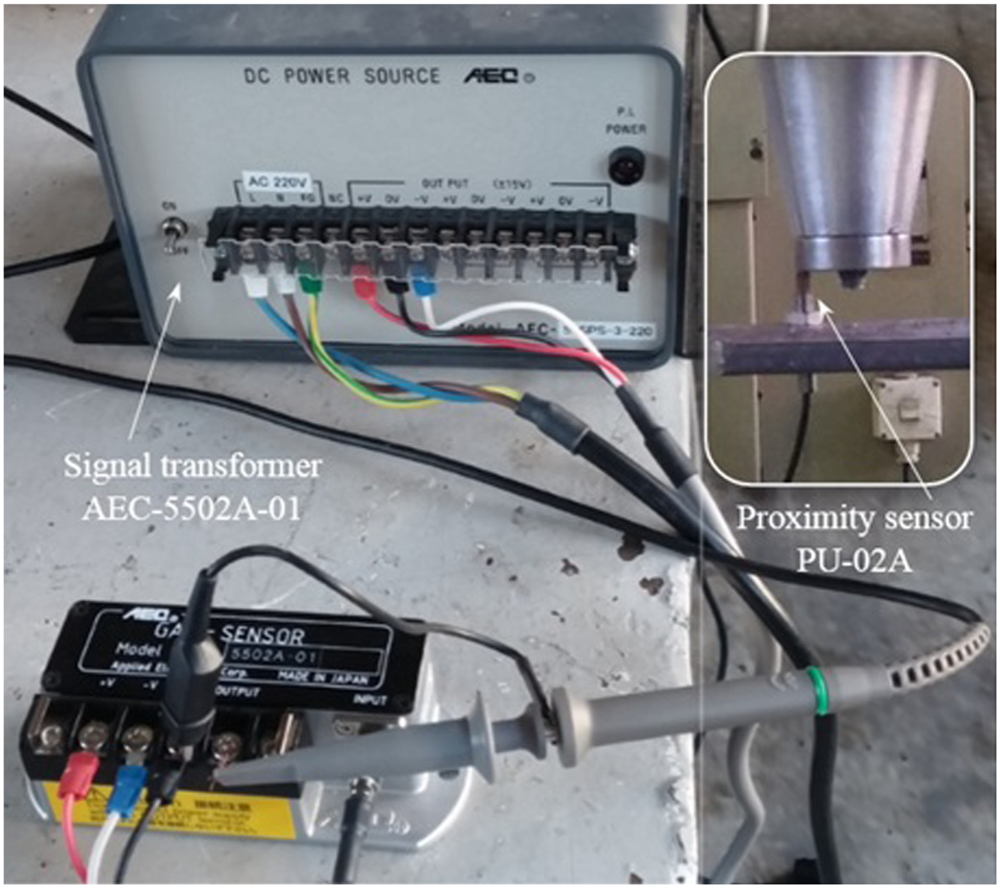
Proximity sensor PU-02A and Signal transformer AEC-5502A-01 to measure amplitude of vibrations.
Gap sensor working principles
The gap sensor like other proximity sensors measures displacements of UaFSW tool tip, and a converter converts it to electrical signals. As Figure 8 illustrates, induced weak signals, first, were amplified by the electrical transducer and then revealed by oscilloscope. Calibration of the sensor test showed that each 5 mV of induced electrical wave on oscilloscope indicates 1 μm of UaFSW tool tip displacement.
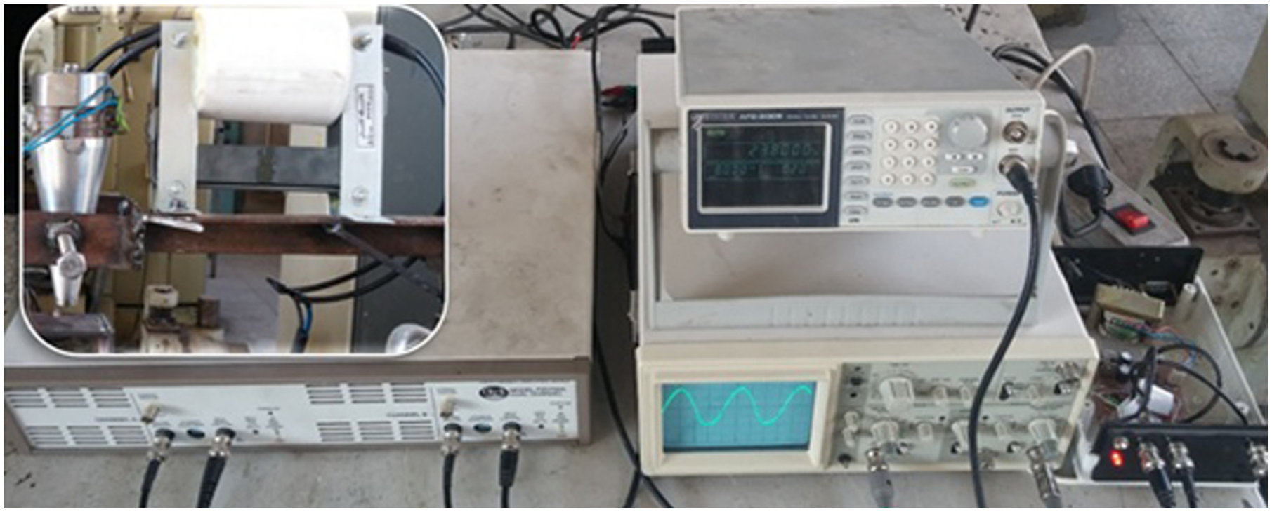
Amplitude measurement setup of UaFSW tool.
According to Figure 7, amplitude of UaFSW vibrations was measured by clamping the tool set from the flange (position of node wave) vertically above the gap sensor. Therefore, first, the UaFSW tool was vibrated in both bending and axial modes through the MPI ultrasonic generator. Then, as Figure 9 shows, for the both modes, displacements of three points, N (north), C (center) and S (south) related to the tool shoulder button, were measured.
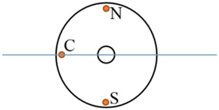
Positions of amplitude measurement.
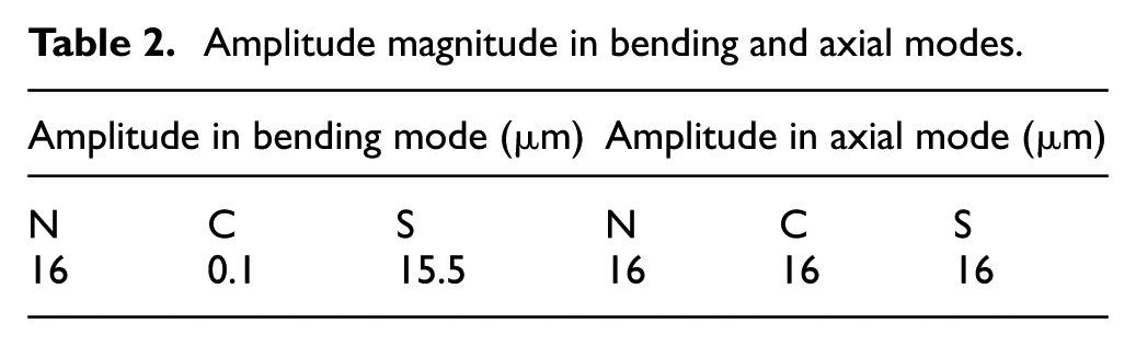
Results of amplitude measurements tests indicated that maximum amplitude for both modes were 16 μm (about 80-mV induced electrical wave). In bending mode, the center point amplitude was reported 0.1 μm, which is near to zero. Considering the flange thickness of 4 mm instead of just a node point was the reason for center point weak vibrations. Table 2 contains amplitude magnitudes of the mentioned positions in Figure 9 for bending and axial modes, respectively.
Amplitude magnitude in bending and axial modes.
Experimental setup
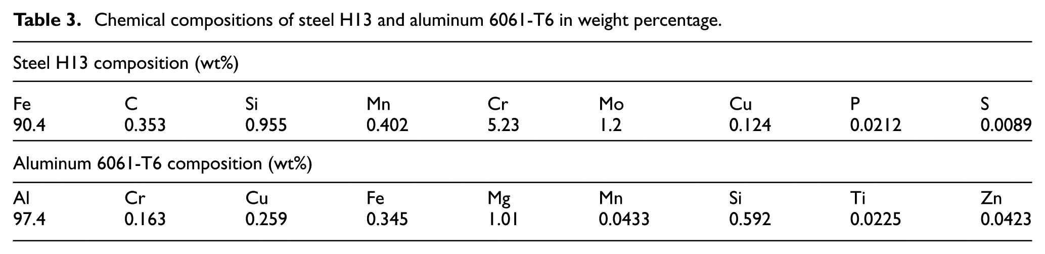
In this study, working material and UaFSW tool insert are aluminum 6061-T6 and hot work tool steel 1.2344 (H13), respectively. Table 3 shows their chemical compositions in weight percentage, which were measured using optical emission spectroscopy (OES) method.
Chemical compositions of steel H13 and aluminum 6061-T6 in weight percentage.
As Figure 10 shows, the experimental UaFSW setup was placed on Tabriz lathe model 4000BR-71TN. In this regard, the assembled UaFSW tool set was put in an electrically insulated mild steel pipe (illustrated in Figure 4) to be clamped in the lathe chuck. Also, dynamometer model Kistler-9257B with precision of 0.5 N (0.0001 × maximum of measurable load range) and Extech-42512, a dual laser infrared thermometer, were used to measure axial welding force and tool tip temperature, respectively.
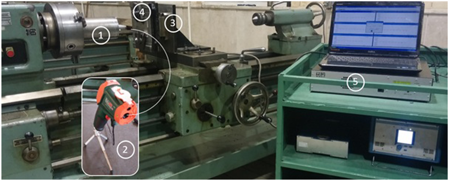
Experimental setup.
Full factorial DOEs
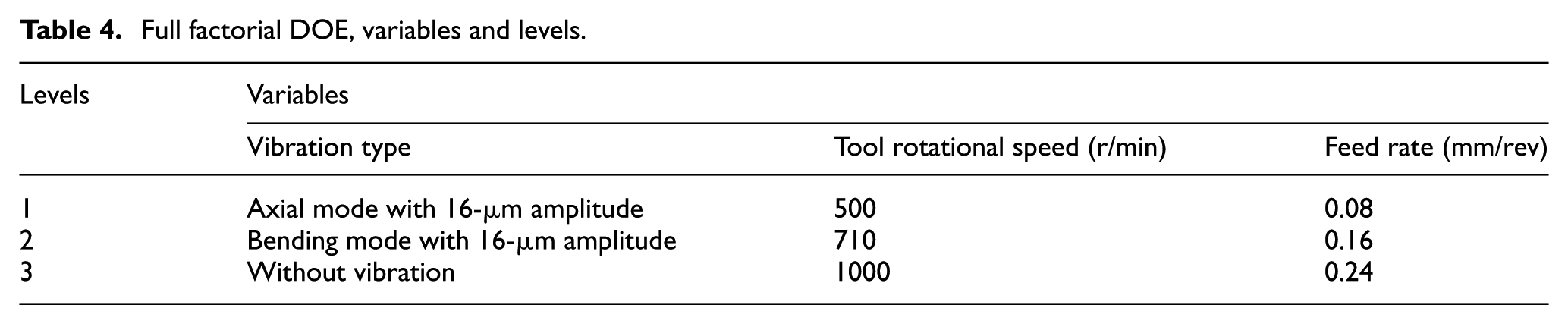
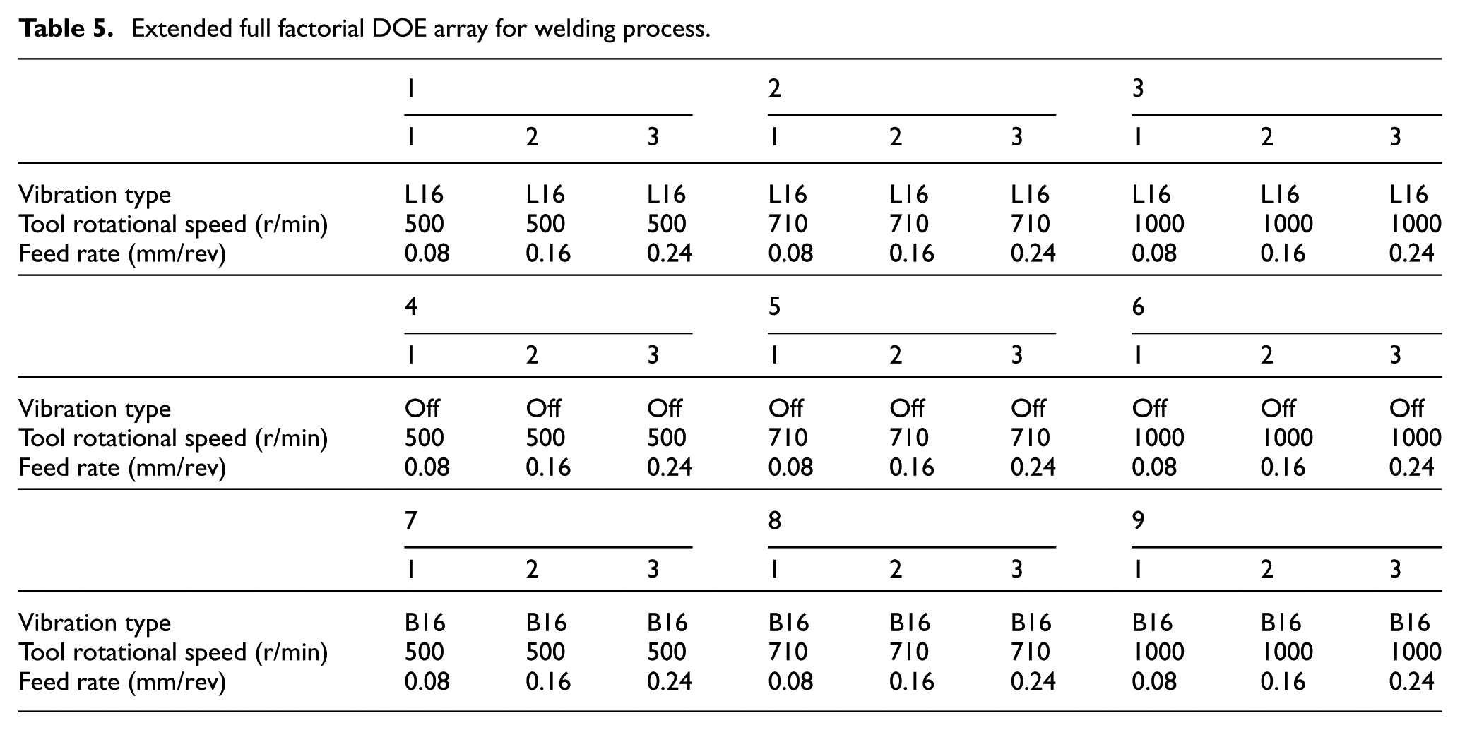
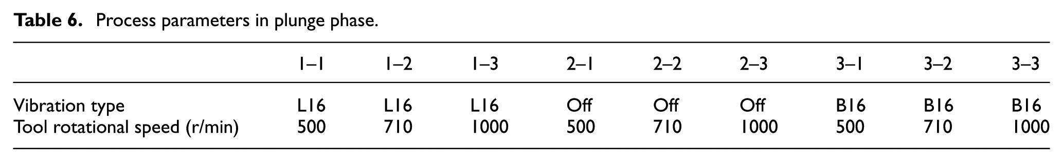
To make a better comparison of axial and bending vibration effects on UaFSW process, a full factorial DOEs, as Table 4 illustrates, was implemented. Process parameters such as welding feed rate, tool rotational speed and vibrations in three levels were selected. Furthermore, Tables 5 and 6 show the extended full factorial DOE array and process plunge parameters, respectively.
Full factorial DOE, variables and levels.
Extended full factorial DOE array for welding process.
Process parameters in plunge phase.
Finally, as illustrated in Figure 11, to investigate the effects of UaFSW parameters on weld quality, according to E8/E8M-11, ASTM standard, 20 the sub-size specimens of tensile tests were prepared.
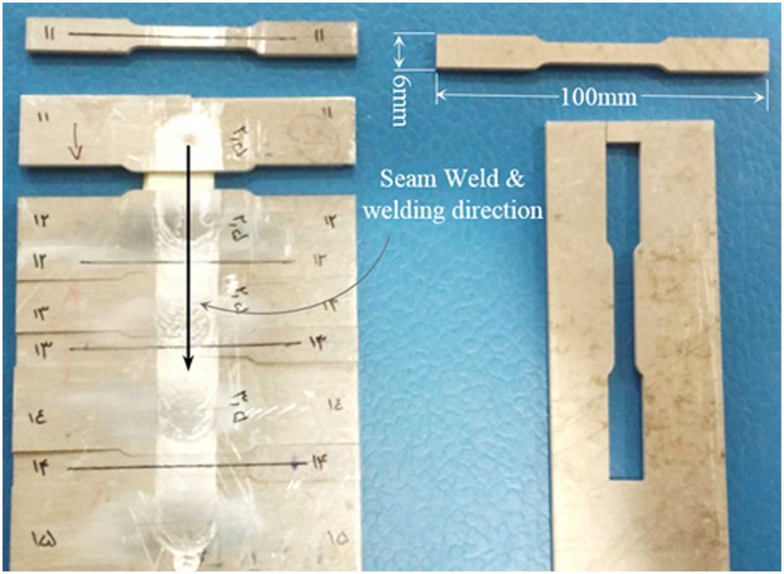
Sub-size tensile test for Al6061-T6 specimens: (a) welded plates and (b) raw plate.
Results and discussion
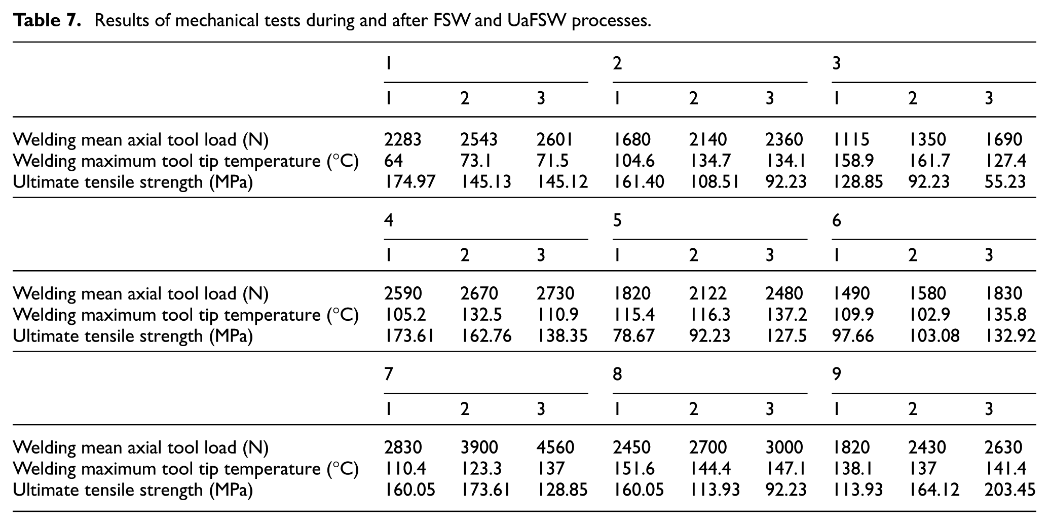
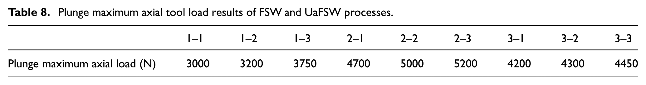
Axial tool force and temperature of shoulder edge (shown in Figure 4(a)) were measured during the FSW process. Also, hardness profile along the weld section of some samples with good quality was obtained about 2 months later the welding of samples. Finally, weld tensile strength of the prepared specimens was measured, using hydraulic press model WP-310. Table 7 illustrates results of the tests mentioned above. Furthermore, results of plunge maximum axial tool load are shown in Table 8.
Results of mechanical tests during and after FSW and UaFSW processes.
Plunge maximum axial tool load results of FSW and UaFSW processes.
Vibration effects on tool axial load
According to Table 7 and Figure 12, tool axial load measurements showed that superimposed axial vibrations cause a decrease in the welding axial load with respect to the state of without vibration, while, applying bending vibrations, in comparison with the state of without vibration, led to an increase in the tool axial load. Like FSW process, in the both modes of UaFSW process, feed rates rise causes an increase in the welding tool axial load, while tool rotational speed rise leads to a decrease in the welding tool axial load. Better working material stirring pattern, in bending mode, causes the load range become much wider than axial and without vibration modes.
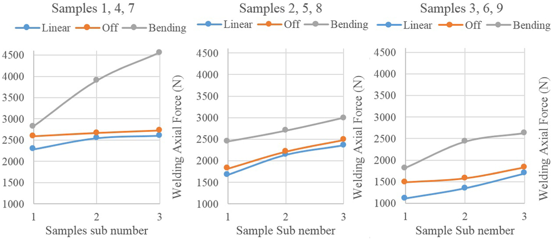
Welding axial force of Table 7 samples.
Considering welding tool axial load results in Tables 7 and 8, maximum tool load occurs in plunge phase. Regarding to Figure 13, superimposed axial and bending ultrasonic vibrations causes a decrease in the axial tool plunge force. But, the reported plunge load in axial mode is less than bending mode, which is due to its more suitable movement pattern for plunge phase. Although the load of welding process in bending mode has the highest magnitude, which is due to its capability to stirring working material, more uniform than other modes, its lesser plunge loads, in comparison with state of without vibration, lead to be an efficient solution in welding of harder metals.
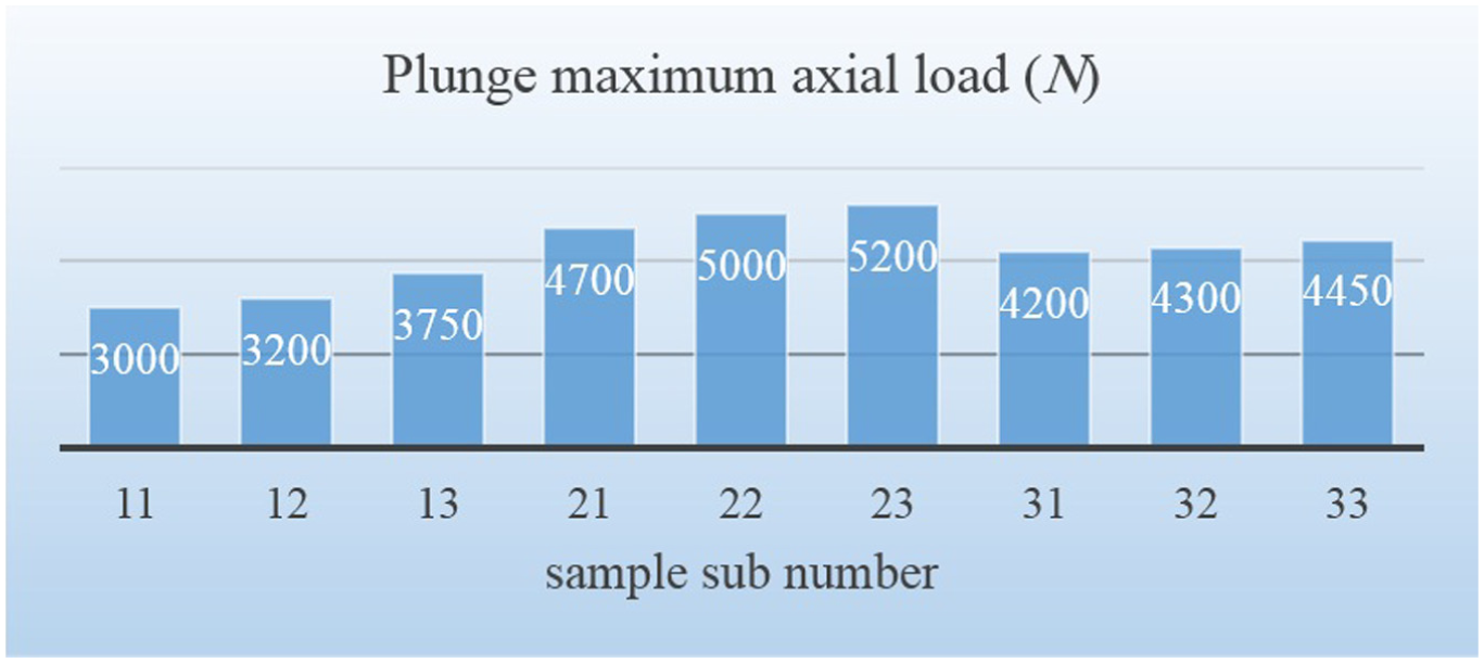
Plunge maximum axial load for process parameters mentioned in Table 6.
Vibration effects on weld tensile strength
The results of tensile tests for welded samples with axial vibrations show that increase in the feed rate and tool rotational speed causes weld tensile strength to decrease. In axial and without vibration modes, maximum weld strength was obtained in the least feed rate and tool rotational speed, 0.05 mm/rev and 500 r/min, respectively. In fact, in these modes, increase in the feed rate causes tool thermal flux to decrease, and as the result, imperfect stir process takes place. Although, increase in tool rotational speed causes more thermal flux, regarding the stirring pattern in axial mode, weak plastic deformation and therefore weak joint strength is inevitable.
As Figure 14 describes, in bending mode, pattern of strength variations are similar to the state of without vibration. It means that, high weld strength is reported for low feed rate and low tool rotational speed. While the mentioned parameters increase, the weld strength, at first, decreases and then increases to the highest levels. In fact, profile of weld strength variations in respect to simultaneous feed rate and tool rotational speed variations are U-shaped. This phenomenon could be described by contributing three effective mechanisms which affected the weld in UaFSW process simultaneously. Tool thermal flux, plastic deformation and types of vibrations are the mechanisms which influence the stirring process. Therefore, decrease in the material stirring, due to low tool rotational speeds or high feed rates, could be compensated by adding bending vibrational energy. Accordingly, higher welding velocities along with increase in the weld quality could be achieved through implementing bending vibrations along with FSW process. As Table 7 illustrates, the highest weld strength is obtained from the sample with process parameters of 0.24 mm/rev feed rate and 1000 r/min tool rotational speed along with bending vibrations.
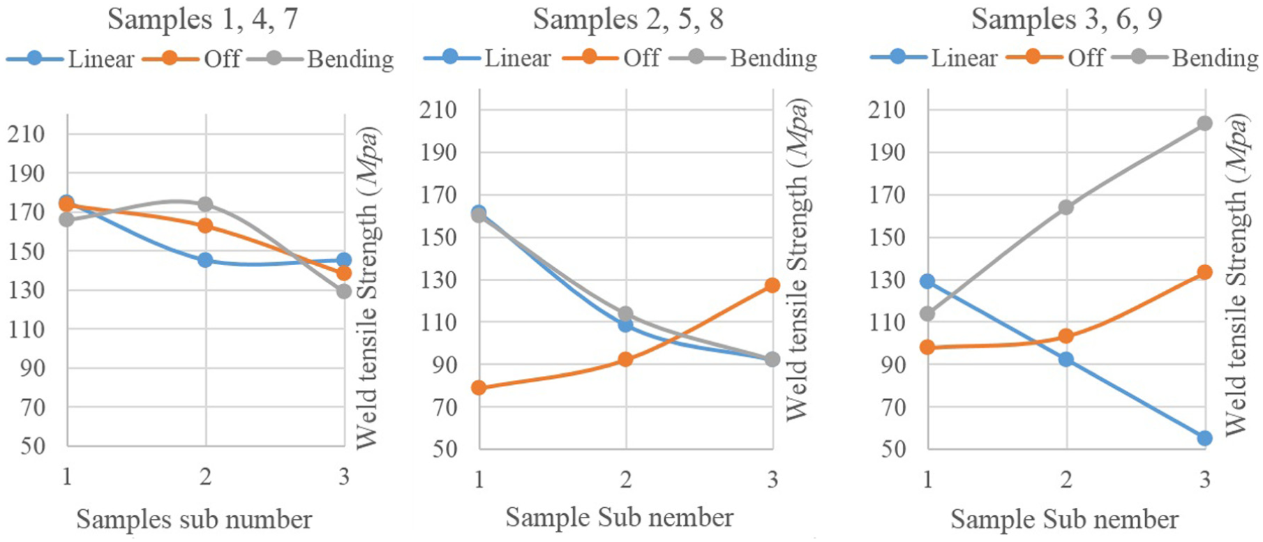
Weld tensile strength of Table 7 samples.
Also, regarding the base metal tensile test results of three prepared specimens in different Al6061-T6 plate directions, the average ultimate tensile strength is reported as 249.56 MPa. Strength comparison results of the weld with highest quality (sample 9–3 in Table 5) and base metal reveal that applying ultrasonic bending vibrations to FSW process is able to create joints with nearly 82% base metal strength.
As Figure 15 shows, for three specimens 3–3, 6–3 and 9–3 (mentioned in Table 5), fracture took place from different regions. Dark point in the specimens indicates the weld advancing side (AS). Position of the weld fracture in sample 9–3, with the highest tensile strength, places on retreating side (RS); whereas, in samples 3–3 and 3–6, the fracture occurs on AS. Furthermore, the fracture section for sample 3–3 with the least tensile strength contains shear in one direction, while for the others, fracture section includes shears in two directions.
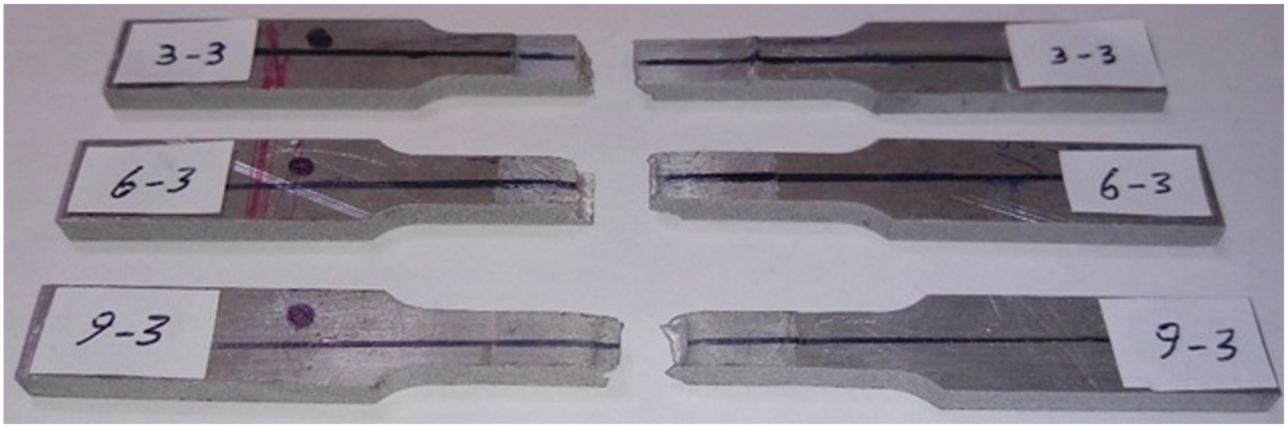
Weld fracture section for three specimens of tensile test: 3–3, 6–3 and 9–3.
Vibration effects on tool shoulder temperature
As Table 7 shows, in contrast to the state of FSW process without vibration, superimposed axial and bending vibrations cause the tool shoulder edge temperature to rise. This is due to the addition of ultrasonic energy to FSW process. Comparison of tool shoulder edge temperatures shows that the temperature in axial mode is higher than bending mode, because in axial vibrations, the whole shoulder section fluctuates, whereas in bending vibrations, the neutral axis is almost stationary and just N and S spots in the shoulder bottom vibrate with maximum amplitude. However, in axial mode, tool shoulder temperature rise does not necessarily lead to working material temperature increase. In fact, in bending mode, vibration patterns contributing to better material stirring, therefore the working material temperature increases.
Relations between weld strength and hardness profile
In order to investigate the effects of superimposed axial and bending vibrations to friction stir welded joints on hardness of the weld section, samples with 1000 r/min tool rotational speed and 0.024 mm/rev feed rate (samples 3–3, 6–3 and 9–3) were cut with computer numerical control (CNC) wire cut along their weld cross section. Then, section of the mentioned samples was polished by sandpapers with mesh numbers of 80, 200, 600, 1000, 1500 and 2500, respectively. Vickers microhardness (HV) testing was conducted on the samples (which were left aside for 2 months), at mid-thickness across the weld zone, applying a load of 100 g and a dwell time of 15 s.
Results of HV profiles are depicted in Figure 16. Suitable stirring work material in sample with bending vibrations causes its HV profile to become more uniform than the others. In other words, the inconsiderable hardness difference between AS and RS of this sample causes more weld strength, while, the HV profiles of other samples, especially for sample with axial vibrations, express large differences between AS and RS.
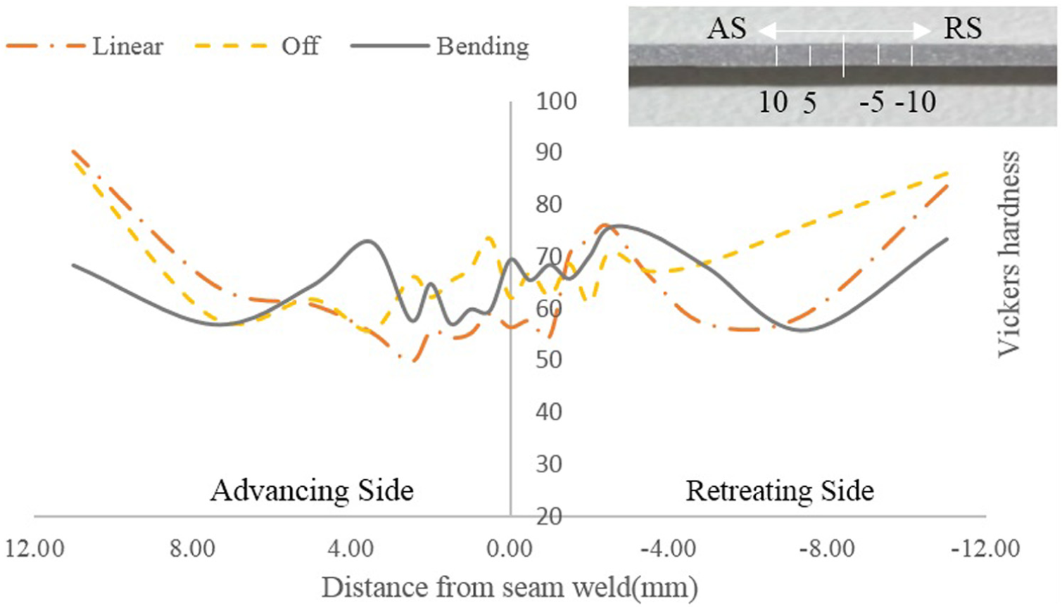
Vickers hardness profiles of welded joints with 1000 r/min rotational speed and 0.24 mm/rev feed rate.
Conclusion
This study experimentally focuses on the effects of superimposed ultrasonic vibrations in bending and axial modes on FSW process. In this regard, in order to make a proper comparison of the mentioned ultrasonic modes, a UaFSW tool set with special geometry capable of vibrating in different resonance frequencies for axial and bending modes was designed and manufactured. Then, a table of full factorial DOEs was used to investigate the effects of UaFSW process parameters on the welding outputs. The results of UaFSW experimental testing express the following:
In welding phase, applying bending vibrations, in comparison with the axial and state of without vibration, leads to an increase in the tool axial load which contributes to better stirring work material.
In plunge phase, both axial and bending modes reduce the plunge tool loads.
Superimposition of the both vibrational modes to FSW process causes tool shoulder edge temperature to increase.
More uniform Vickers hardness profile for friction stir welded samples with bending vibrations leads to better stirring conditions, and finally, the weld with the highest strength will be its consequence.
Footnotes
Appendix 1
Declaration of conflicting interests
The author(s) declared no potential conflicts of interest with respect to the research, authorship and/or publication of this article.
Funding
The author(s) received no financial support for the research, authorship and/or publication of this article.