
Abstract
In this article, a cutting forces model for micro flat end milling is developed by regarding tool run-out or eccentric and tilt deviation of tool path as well as the effect of bottom edge cutting. Since the chip thickness is comparable to the edge radius, the size effect, which means the chip is only removed when it is higher than a certain value, is also taken into account. Therefore, cutting forces of the proposed model are calculated by flank shearing, flank ploughing and bottom edge cutting mechanisms in the shearing-domain and ploughing-domain regimes. The coefficients of cutting forces and tool run-out parameters can be calibrated by the experimental cutting forces. The predicted cutting forces with different feed rates and axial depths of cut based on the proposed model have been investigated and compared with experimental results for Al6061. The predicted and measured cutting forces are in good agreement.
Keywords
Introduction
The micro flat end milling, frequently viewed as a downscaled traditional milling process, is one of the most widely used machining method in the precision manufacturing, electronic and biomedical industries, molds and aerospace components to mention a few as Srinivasa and Shunmugam 1 and Uriarte et al. 2 describe. The cutting forces model is essential in order to predict the machining process behavior ahead of costly real experiments and increase the machining productivity. An accurate prediction of cutting forces is the basis for the monitoring machining process and selecting optimal cutting parameters.
Many research efforts have been focused on the application of the milling mechanism to calculate cutting forces. Chen et al. 3 developed a cutting forces model, which assumes a semi-stationary process for the serrated chip formation in end milling of titanium alloy Ti6Al4V. In order to extend the prediction model, the end mill is discretized into several axial slices, and cutting forces are regarded as an equivalent shearing mechanism. Gonzalo et al. 4 proposed the mechanistic methods, which take into account geometrical characteristics of process and empirical specific cutting coefficients obtained from experimental work to predict cutting forces. Wan et al. 5 identified the cutting force coefficients using the measured instantaneous cutting forces. The specific cutting force coefficients in ball-end milling are determined based on a linear mechanistic model at a higher range of rotational speeds, as Dikshit et al. 6 do. A number of researches, like Altintas et al., 7 have shown that the rubbing/ploughing effect associated with the clearance face of tool flank and the machined workpiece surface is responsible for the cutting process damping. Wang and Zheng 8 proposed the dual-mechanism method of treating the shearing and edge rubbing/ploughing forces separately. Based on the above dual-mechanism method, Wang and Zheng 9 developed an analytical model for the direct identification of global shearing and ploughing cutting constants from measured average cutting forces in ball-end milling. Wang and Zheng 10 also presented a method for the identification of tool offset through milling force without requiring the specific cutting coefficients to be known as priori. The presented identification process requires only two cutting tests and two linear algebraic equations. Gonzalo et al. 11 calculated the specific cutting force coefficients with an inverse method using the identification of predicted and measured cutting forces in the time domain.
Although similar to the macro scale flat end milling, the micro flat end milling cannot be directly regarded as a downscaled version of the macro scale flat end milling process. 12 The micro milling process has specific characteristics, such as the size effect, the tool edge radius and the minimum chip thickness. 13 To predict cutting forces in the micro milling process, Kim et al. 14 developed a static chip model accounting for the coupled minimum chip thickness and edge radius effects. Kang et al. 15 presented the cutting force behavior resulting from the effect of cutting edge radius in the micro-scale milling of AISI 1045 steel using tungsten carbide tools. In order to calculate the ploughing component of cutting forces, a slip-line field model was proposed by Fang. 16 Jun et al. 17 also developed a more complicated slip-line plasticity mode considering the elastic–plastic deformation and elastic recovery. Huang et al. 18 employed the finite element method and experimental analyses to estimate the micro milling cutting force. Another vital issue for building the cutting forces model is the trajectory of tool path. In the macro milling process, the feed per flute is much smaller than the tool radius, and then tooth trajectory can be assumed as a circle. However, when the ratio of feed per flute and the tool radius are increased, the above assumption is no longer valid. Bao and Tansel 19 presented the chip thickness model containing the tooth trajectory as the tool simultaneously moves and rotates. Meanwhile, an analytical cutting forces model was developed with a compact expression for chip thickness considering tool run-out in the micro milling. 20 The chip thickness models combining the exact trochoidal trajectory of tool tip, tool run-out and the minimum chip thickness are also studied by Li et al. 21 and Lu et al. 22
The above work only considered the flank edge effect with negligence of contribution of the bottom edge on cutting forces. Dang et al. 23 first proposed the cutting forces model contributed by both the flank edge–induced shearing and the bottom edge cutting effect simultaneously. Wan et al. 24 extended the cutting forces model including flank shearing, flank rubbing and bottom cuttings. However, since the specific characteristics such as the size effect, the tool edge radius and the minimum chip thickness which should also be considered, the effect of bottom edge on cutting forces is still a new challenge for micro flat end milling process.
This article proposed a new cutting forces model for micro flat end milling that includes three cutting mechanisms of flank shearing, flank ploughing and bottom edge cutting in shearing-dominant and ploughing-dominant regimes separately. The influences of cutting edge size effect, the trochoidal trajectory of tool tip and tool run-out are also considered in the proposed model. In addition, novel procedures are presented to calibrate the three cutting coefficients related to chip removal, flank ploughing and bottom edge cutting effects, and the tool run-out parameters in micro flat end milling.
Development of the cutting forces model
Determination of instantaneous uncut chip thickness
Prior modeling of the instantaneous uncut chip thickness, it is essential to introduce the geometry parameters of micro flat end milling process. The Cartesian coordinate system of micro flat end milling process with a two-flute tool is shown in Figure 1. The corresponding origin is located at the center of tool bottom. The x-axis is along the feed direction, the y-axis is transverse to the feed direction and the z-axis is along the tool axis direction. In order to calculate cutting forces more conveniently, the axial cutting part of tool is divided into K disk elements by an equivalent axial length.

where j is the tooth index,
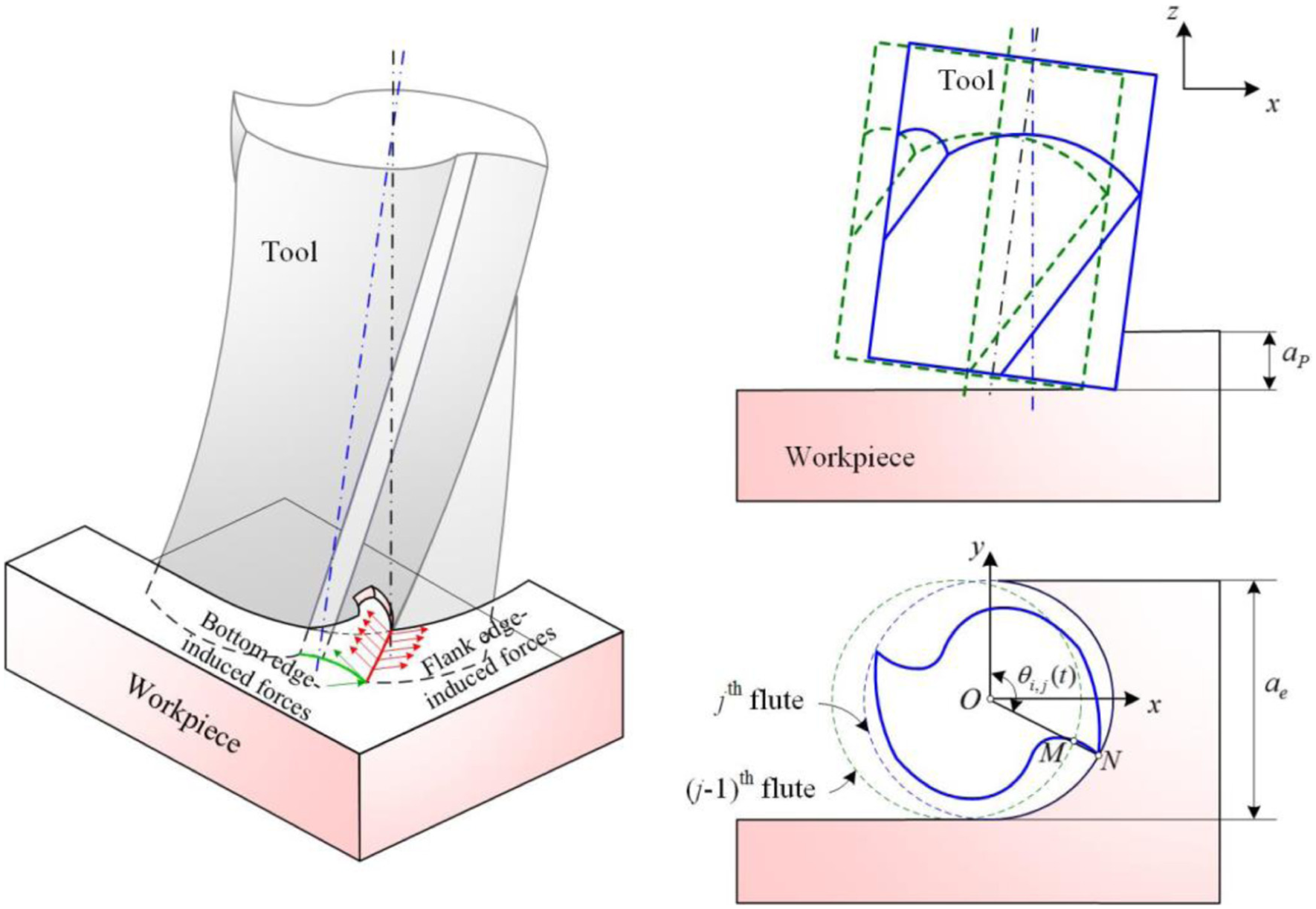
Geometry parameters of micro flat end milling process.
In the micro milling process, the small run-out that affects the cutting force profile of the macro milling process very little creates drastic force variations in micro milling process. The assumption of circular tool path, which is used in the macro milling generally, cannot be used any more in micro milling. In accordance with tool run-out effect, the mathematical model of trochoidal tool path to determine the instantaneous uncut chip thickness is used.
25
The tool run-out can be specified with angular and radial run-out.
26
The related parameters are offset distance
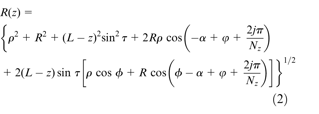
where R is the radius of tool and L is tool overhang length of tool after tool installation.
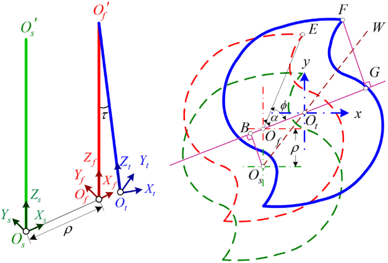
Geometric model of tool run-out with axis offset and tilt: (a) tool run-out in micro milling and (b) section view of tool run-out.
According to the above defined actual cutting radius, the related deviations caused by tool run-out in x-axis and y-axis are calculated as follows
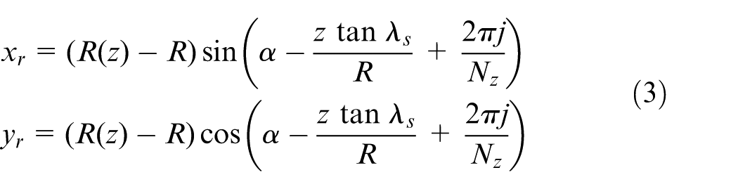
and the direction angle of tool axial offset changes with spindle speed as

where
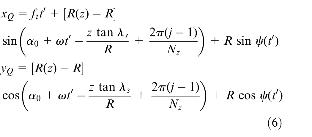
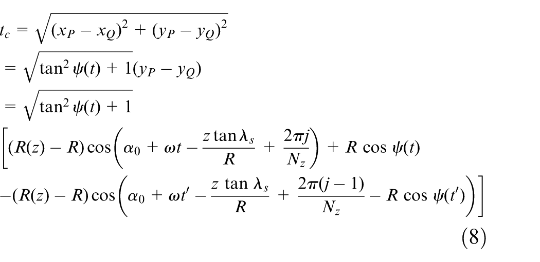
Figure 3 shows the trajectories of the (j − 1)th and jth tooth considering tool run-out. The solid line curve and dashed line curve describe the trajectories with and without tool run-out, respectively. The coordinates of point P on the jth tooth can be represented as
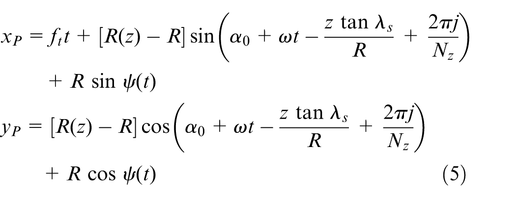
where
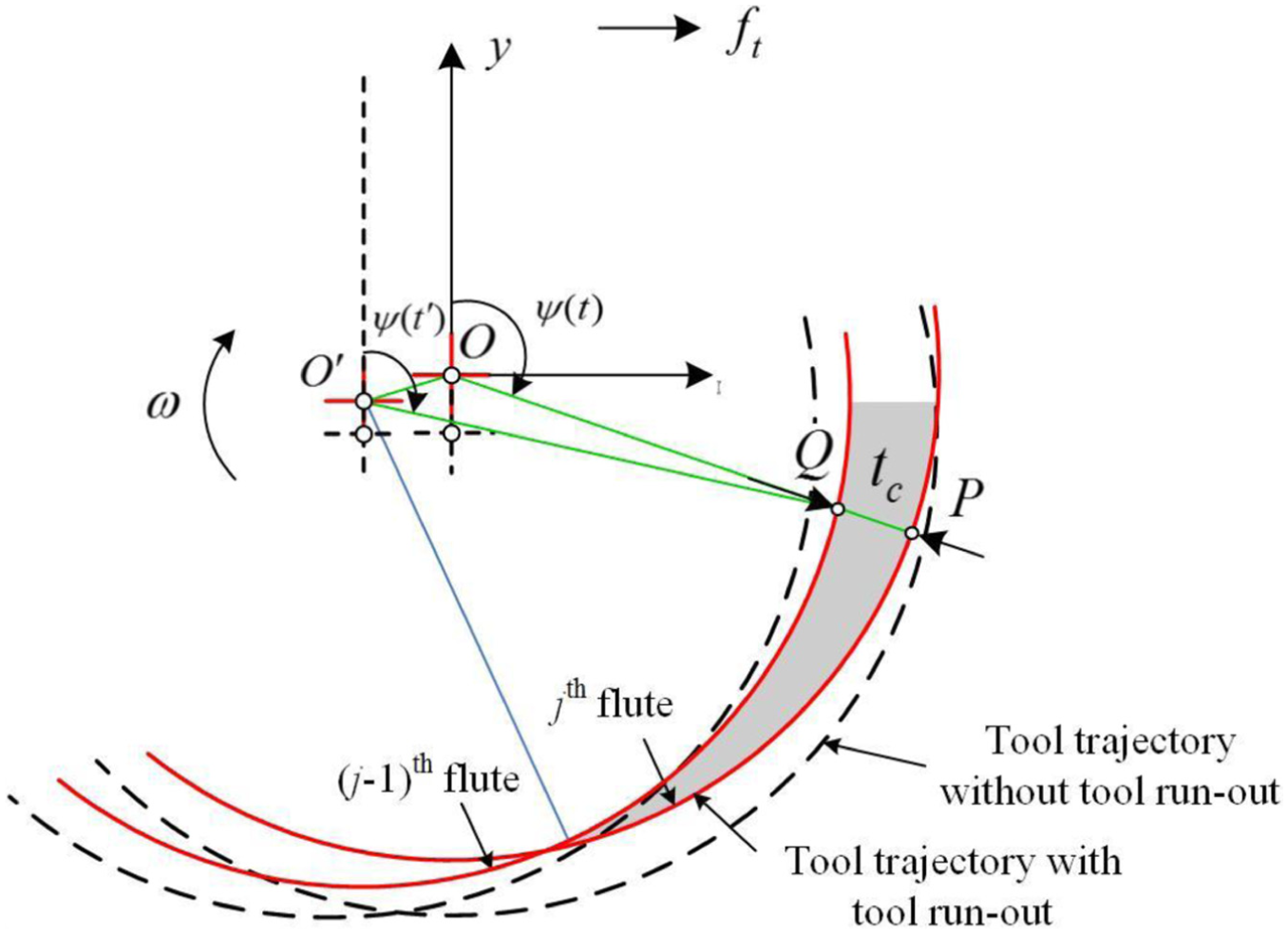
Trajectories of the (j − 1)th and jth flute with tool run-out in micro flat end milling process.
The time
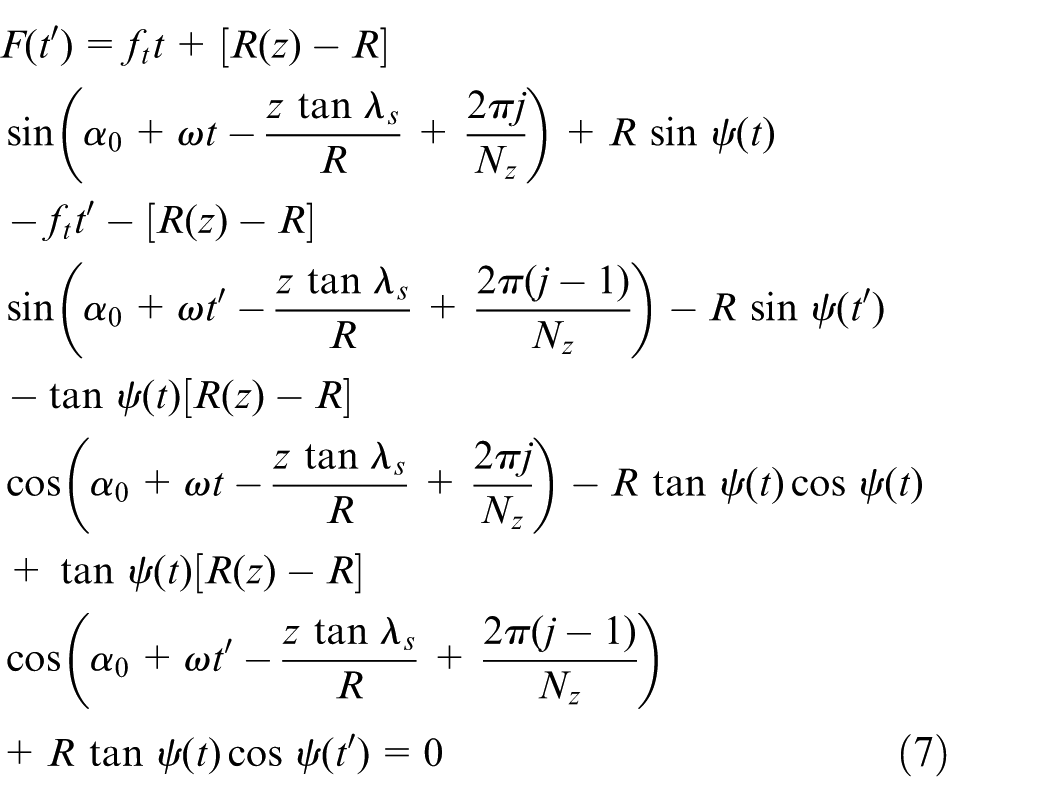
To solve time
Calculation of cutting forces considering bottom edge cutting effect
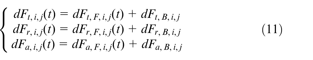
As both the flank and bottom edges of tool are in contact with workpiece in the micro flat end milling process, the total cutting forces are composed of flank edge–induced forces and bottom edge–induced forces. The total cutting forces can be expressed as follows
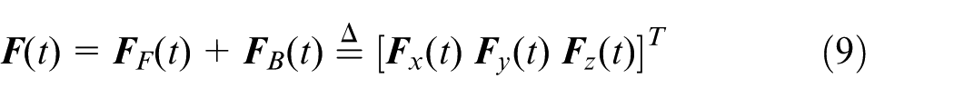
where
Since the chip thickness is in the same order of magnitude as the tool edge radius in micro flat end milling, the cutting edge is considered as a rounded surface not a line. Özel et al. 28 put forward that the chip cannot be removed by tool under some conditions on account of the roundness of tool edge, namely, the material is not cut by tool until the chip thickness reaches the minimum chip thickness. The minimum chip thickness can be calculated by 28

where
On account of the above mentioned minimum chip thickness, the total cutting forces of micro flat end milling process are modeled in two separate cutting mechanisms, that is, chip formation (shearing-dominant) and ploughing without chip formation (ploughing-dominant) regimes, respectively.
Cutting forces model in shearing-dominant regime
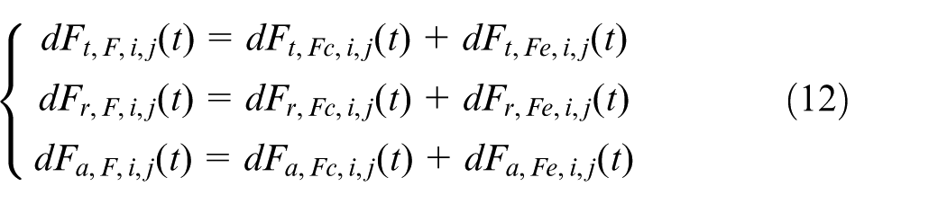
When the instantaneous uncut chip thickness is bigger than the minimum chip thickness, the micro flat end milling is dominated by the shearing mechanism as all of machined materials are assumed to be removed as chip. In the shearing-dominant regime, the total cutting forces are composed of flank edge–induced shearing cutting forces, flank edge–induced ploughing cutting forces and bottom edge–induced cutting forces as
where
The detailed calculation procedure of the flank edge–induced cutting forces and bottom edge–induced cutting forces are given as follows:
1. Calculation procedure of the flank edge–induced cutting forces
The cutting forces acting on the ith axial disk element of the jth flute consist of the cutting forces components induced by the chip removal and flank ploughing effects
where
where
Considering the geometric conditions
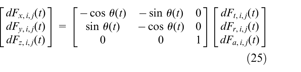
The flank edge–induced cutting forces
The transformation matrix
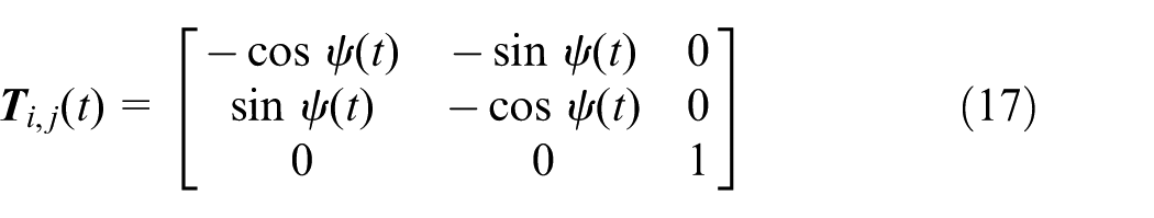
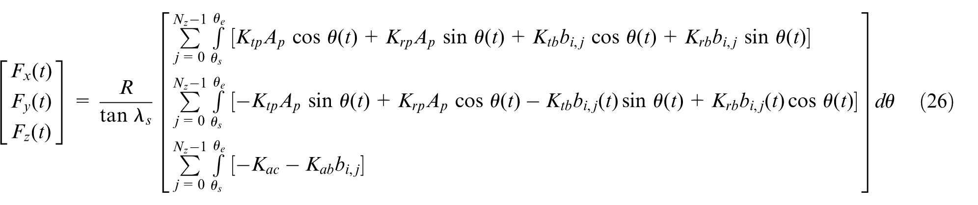
By the integration along flute, the expressions for total cutting forces acting on the flank edges of tool in x-axis, y-axis and z-axis are
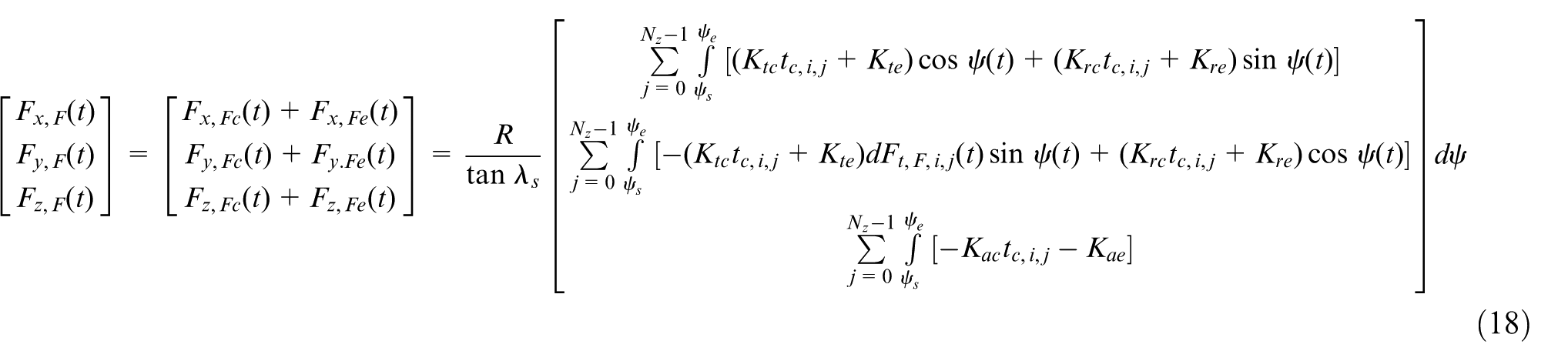
where
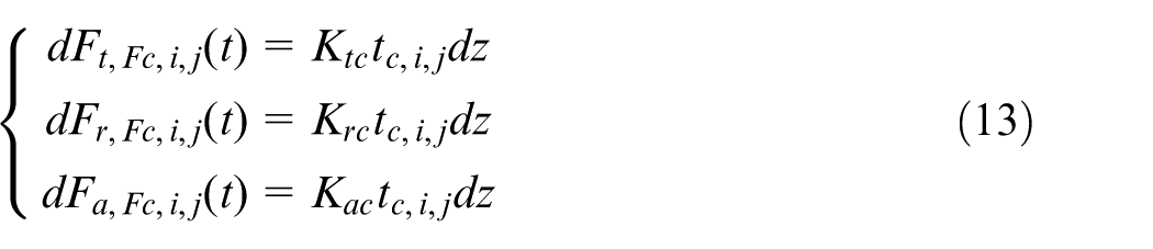
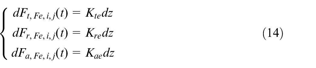
2. Calculation procedure of the bottom edge-induced cutting forces
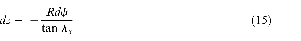
The cutting mechanism of the bottom edge of tool in the micro flat end milling is similar to the ploughing process of the flank edge. 21 As the flank edge–induced ploughing cutting forces can be modeled by a linear function of axial depth of cut, the bottom edge–included cutting forces are also calculated as a linear function of the bottom uncut chip width, which is equal to the length of the bottom contact line MN as shown in Figure 1. Therefore, the bottom edge–induced cutting forces in the tangential, radial and axial directions can be written as
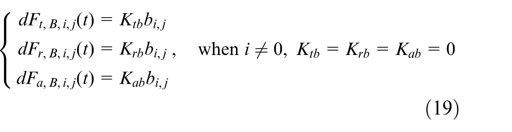
where
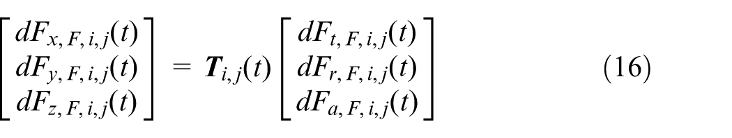
Transforming the tangential bottom edge–induced cutting forces
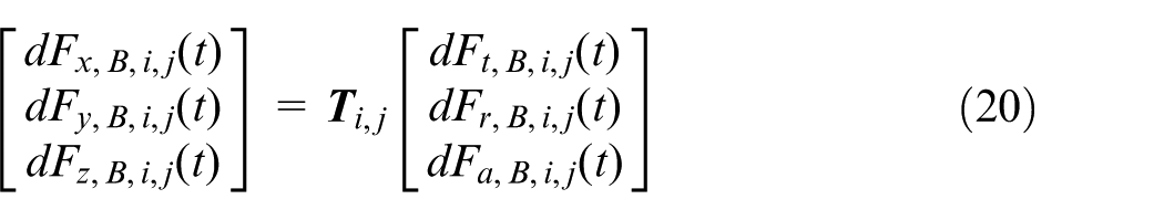
Integrating the cutting forces components in equation (20) for different flutes, the expressions for total cutting forces acting on the bottom edges of tool in x-axis, y-axis and z-axis are
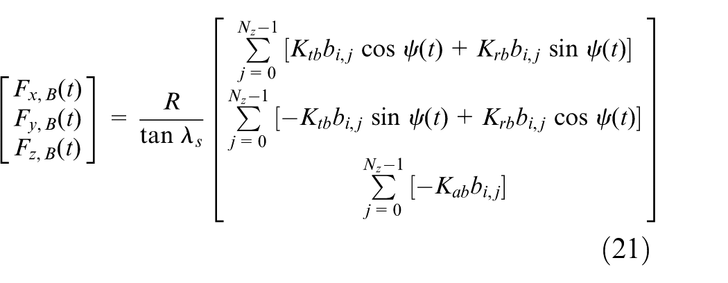
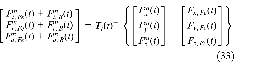
Therefore, based on the total cutting forces acting on the flank edges of tool in equation (18) and acting on the bottom edges of tool in equation (21), the total shearing-dominant regime cutting forces in the x-axis, y-axis and z-axis can be expressed as
Cutting forces model in ploughing-dominant regime
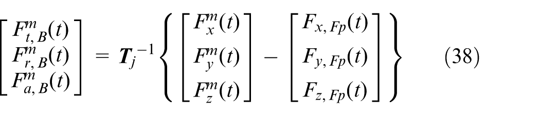
When the instantaneous uncut chip thickness is smaller than the minimum chip thickness, the micro flat end milling is dominated by the ploughing mechanism. The machined material deforms elastically and plastically in the interaction zone with the tool, and there is no material to be removed during machining process. In the ploughing-dominant regime, the cutting forces are composed of flank edge–induced ploughing cutting forces and bottom edge–induced cutting forces as
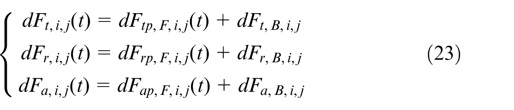
where
Based on the relationship between ploughing cutting forces and contact engagement zone, the tangential, radial and axial element ploughing cutting forces components, namely,
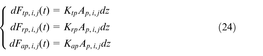
where
The calculation procedure of the bottom edge–induced cutting forces in the ploughing-dominant regime is similar to that in the shearing-dominant regime, and the bottom edge–induced cutting forces can also be obtained from equation (21).
The cutting forces
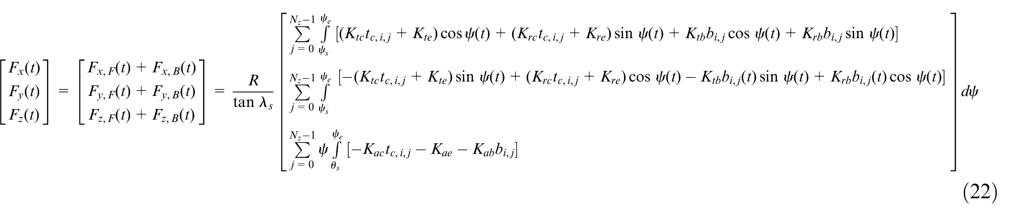
By the integration along flutes, the expressions for total cutting forces acting on the flank edges of tool in x-axis, y-axis and z-axis are
Calibration procedure of tool run-out parameters and cutting forces coefficients
From section “Development of the cutting forces model,” it can be seen that the accuracy of the proposed cutting forces model is mainly decided by the calibration of tool run-out parameters and cutting forces coefficients. The calibration procedure 23 in the shearing-dominant and ploughing-dominant regimes of micro flat end milling is described in detail in the following.
Calibration of tool run-out parameters
As indicated in the previous works, 29 the non-linear relationship exists between the cutting forces coefficients and the instantaneous uncut chip thickness. The cutting forces coefficients increase sharply when the uncut chip thickness is smaller than the minimum chip thickness, which is caused by the cutting edge size effect. When the uncut chip thickness increases beyond the minimum chip thickness, the size effect becomes very weak and the cutting forces coefficients are assumed as constant. Meanwhile, the feed per flute is also selected to be large enough to weaken the size effect.
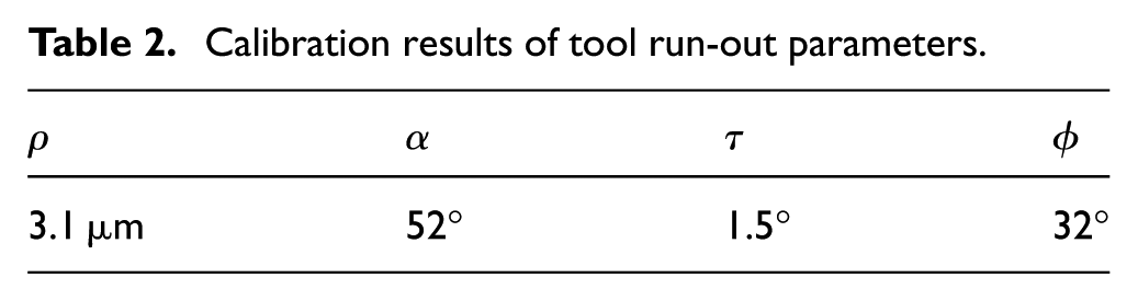
The parameters of tool run-out,
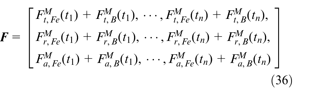
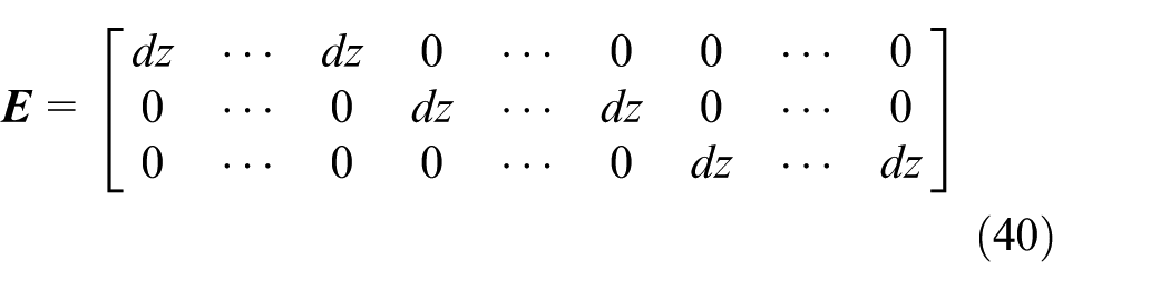
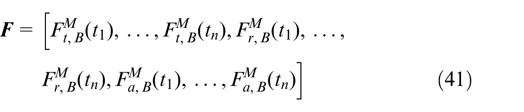
Under the cutting conditions of experiments, only one flute of tool is involved in machining process. Therefore, the measured cutting forces at time t can be expressed by the summation of cutting forces acting on each disk
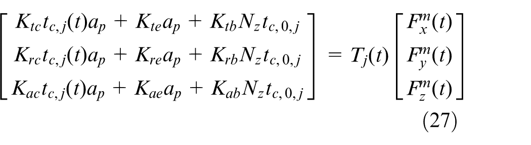
Set
For all selected time value
With equation (27) and the value of
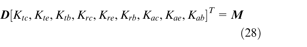
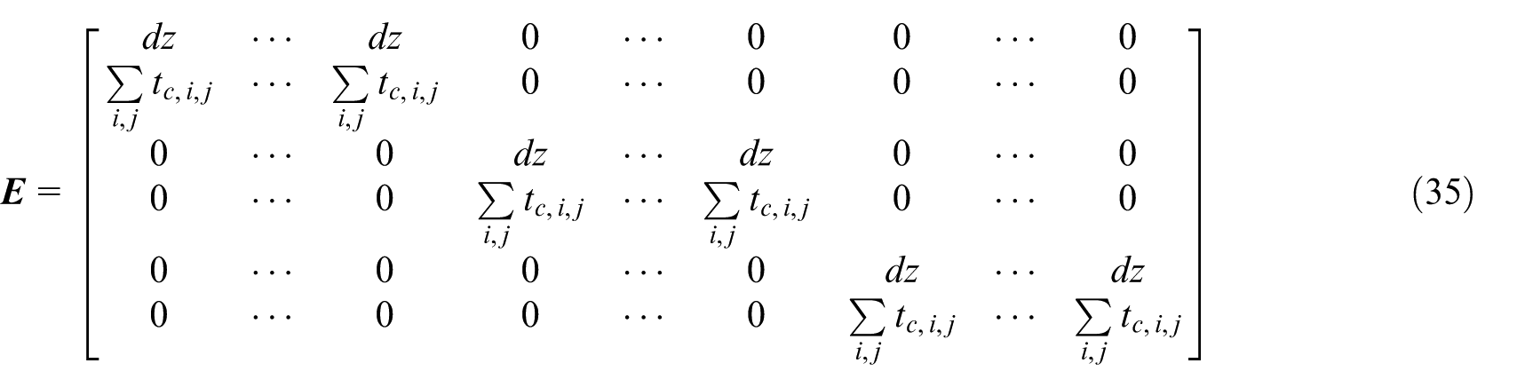
Determine cutting forces coefficients related to the flank edge and bottom edge by the following equation
Substitute the above calculated cutting forces coefficients from equation (31) into equation (22), and then the convergence for the solution of equation (31) is calculated as
When
Calibration of cutting forces coefficients related to flank and bottom edge
In the shearing-dominant regime, the cutting mechanism of micro flat end milling process is similar to that in the macro milling process. The cutting forces coefficients are related to the flank edge and bottom edge.
It can be seen from the cutting forces model in section “Development of the cutting forces model,” the tangential, radial and axial cutting forces are approximately linear to the chip load, which is equal to
The transformed measured cutting forces in tangential, radial and axial directions are plotted with the chip load
Considering the calibrated tool run-out parameters and the determined shearing cutting forces coefficients, the shearing cutting forces
where
The above equation can be rewritten as

Then, the coefficients

In the ploughing-dominant regime, the machined workpiece is under elastic deformation and no material is supposed to be removed. The cutting forces in this regime consist of ploughing cutting forces with the flank edge and bottom cutting forces with the bottom edge. The corresponding cutting forces coefficients are described in detail.
Similar with the calibration procedure of shearing cutting forces coefficients
In accordance with the calibrated ploughing cutting forces coefficients, the ploughing cutting forces related to the flank edge in the ploughing-dominant regime can be obtained using equation (24). Then, combining the measured total cutting forces and calculated ploughing cutting forces, the measured cutting forces induced by the bottom edge can be written as
where
The above equation can be rewritten as

Then, the cutting force coefficients

Compared with the existing approach, the main contributions of the proposed calibration method is as follows: (1) the parameters of tool run-out are determined without prior identified of cutting forces coefficients, which makes the calibration procedure of cutting forces coefficients simplified and (2) the influence of bottom edge cutting in micro flat end milling process is taken into account.
Experiment verifications
A series of cutting tests about micro flat end milling are carried out on an in-house developed milling machine to verify the proposed cutting forces model as well as the calibration approach. The feed system of the developed machine is composed of three high precision linear stages with a resolution of 0.1 μm and an air bearing motorized spindle is used to provide the maximum spindle speed of 110,000 r/min to achieve the required cutting speed. A two-flute carbide micro flat end mill with a diameter of 508 μm, helix angle of
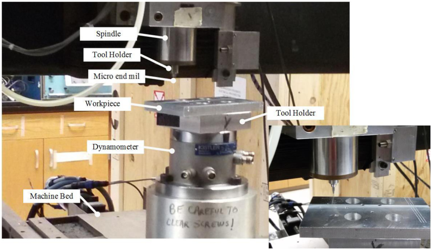
Experimental set-up for cutting forces.
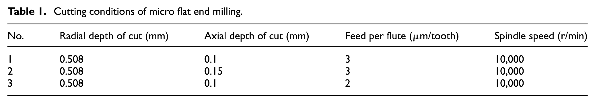
Cutting conditions of micro flat end milling.
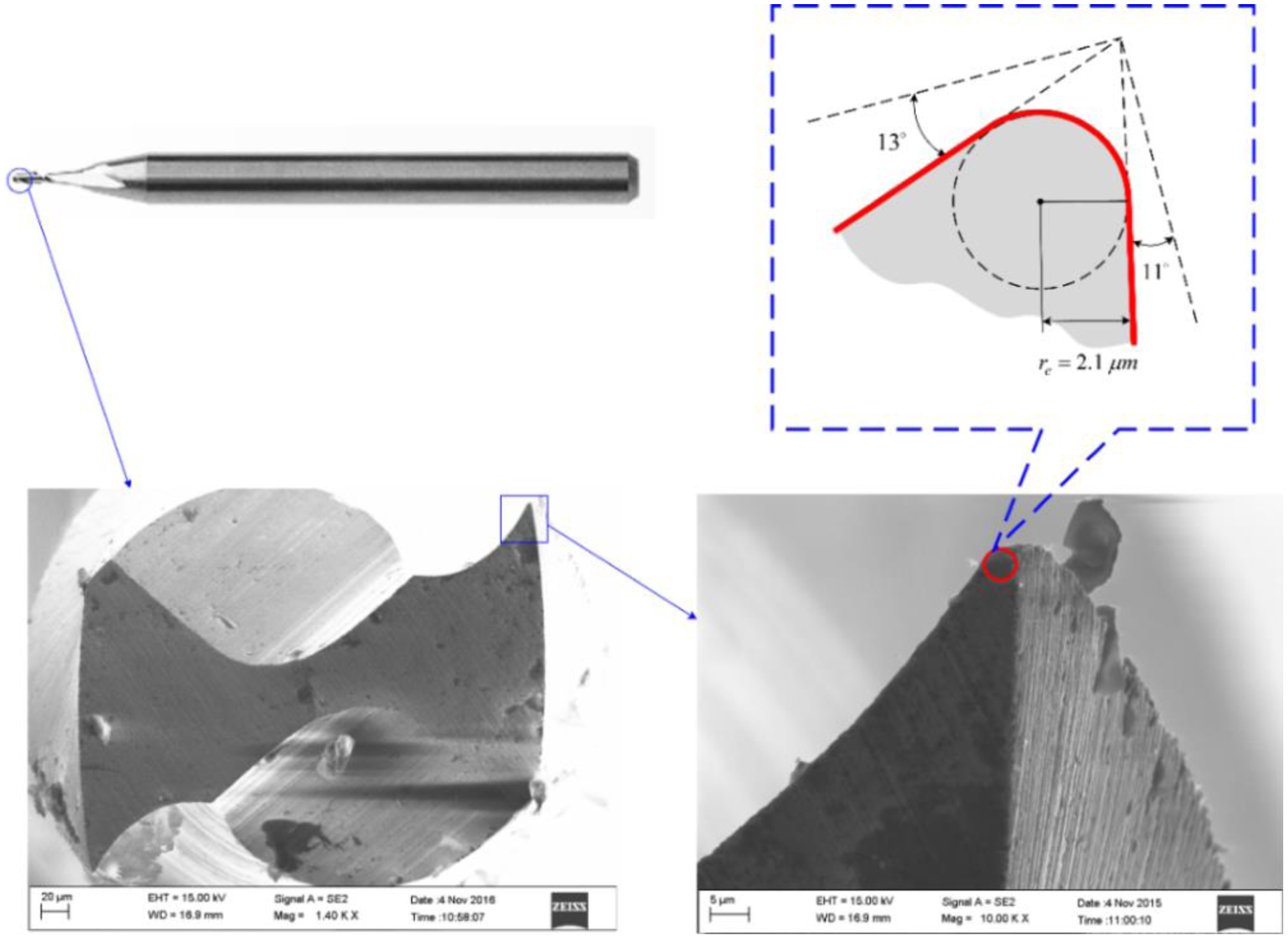
The edge radius of micro end mill.
The parameters of tool run-out and cutting forces coefficients are calibrated using the procedure in section “Calibration procedure of tool run-out parameters and cutting forces coefficients.” According to section “Calibration of cutting forces coefficients related to flank and bottom edge,” the coefficients
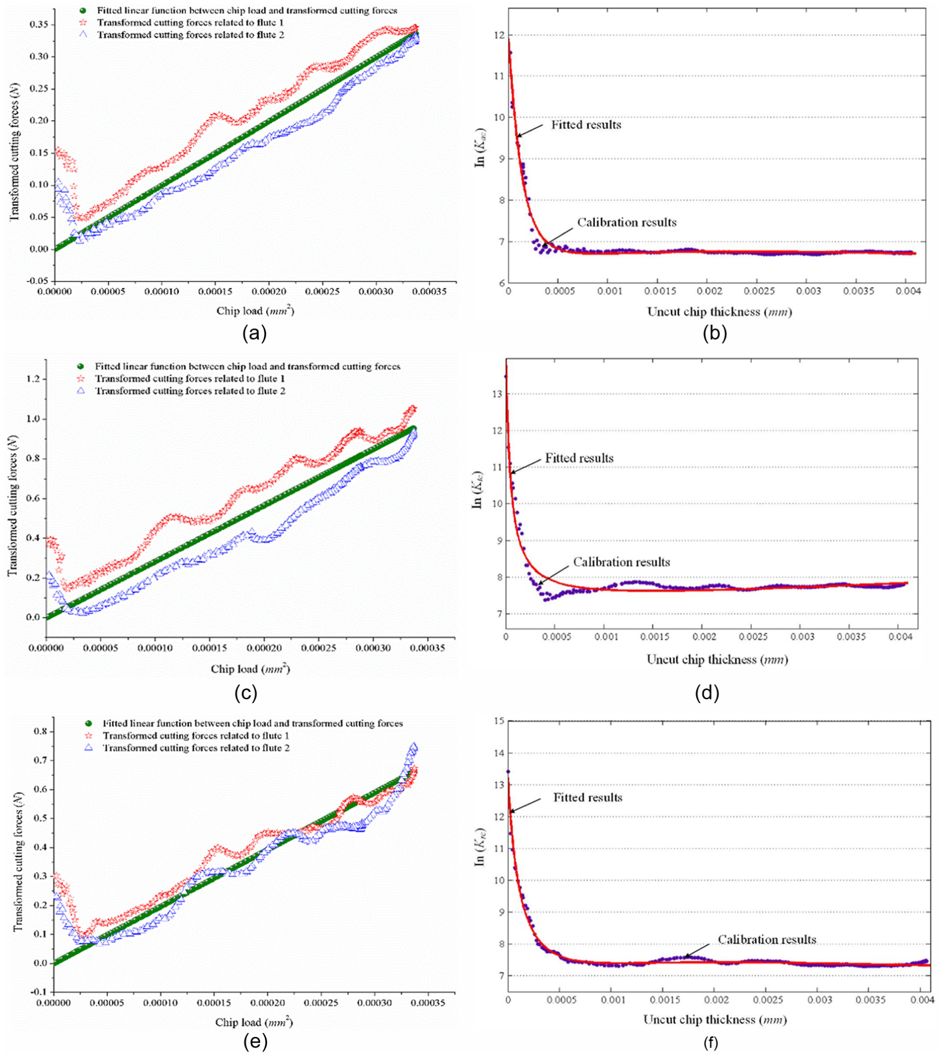
Calibration and fitted results of coefficients related to the flank edge: (a) transformed cutting forces versus chip load in tangential direction, (b) calibration and fitted cutting forces coefficients in tangential direction, (c) transformed cutting forces versus chip load in radial direction, (d) calibration and fitted cutting forces coefficients in radial direction, (e) transformed cutting forces versus chip load in axial direction and (f) calibration and fitted cutting forces coefficients in axial direction.
Figure 6(b), (d) and (f) show the relationship between the total cutting forces in tangential, radial and axial directions and the chip load
Calibration results of tool run-out parameters.
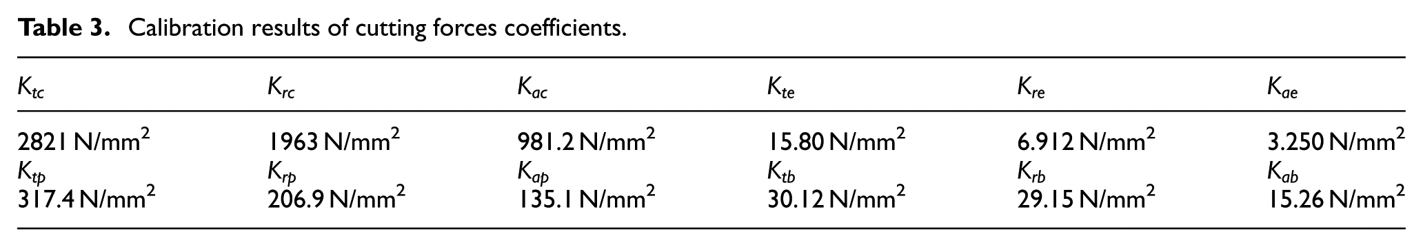
Calibration results of cutting forces coefficients.
In order to verify the accuracy of the proposed cutting forces model, the model with tool run-out developed by Afazov et al. 22 is used for comparison. The prediction of cutting forces can be illustrated in the simulation flow chart as shown in Figure 7. According to the calibration results of tool run-out parameters and cutting forces coefficients, the predicted results by the proposed model and the one given by Afazov et al. 22 are compared with the experimental results under the given different cutting conditions in Table 1. Generally, the predicted cutting forces by both models agree well with experimental results. Furthermore, the predicted cutting forces by the proposed model will be closer to the measured cutting forces, which means the effect of bottom edge cutting cannot be negligible for micro flat end milling process.
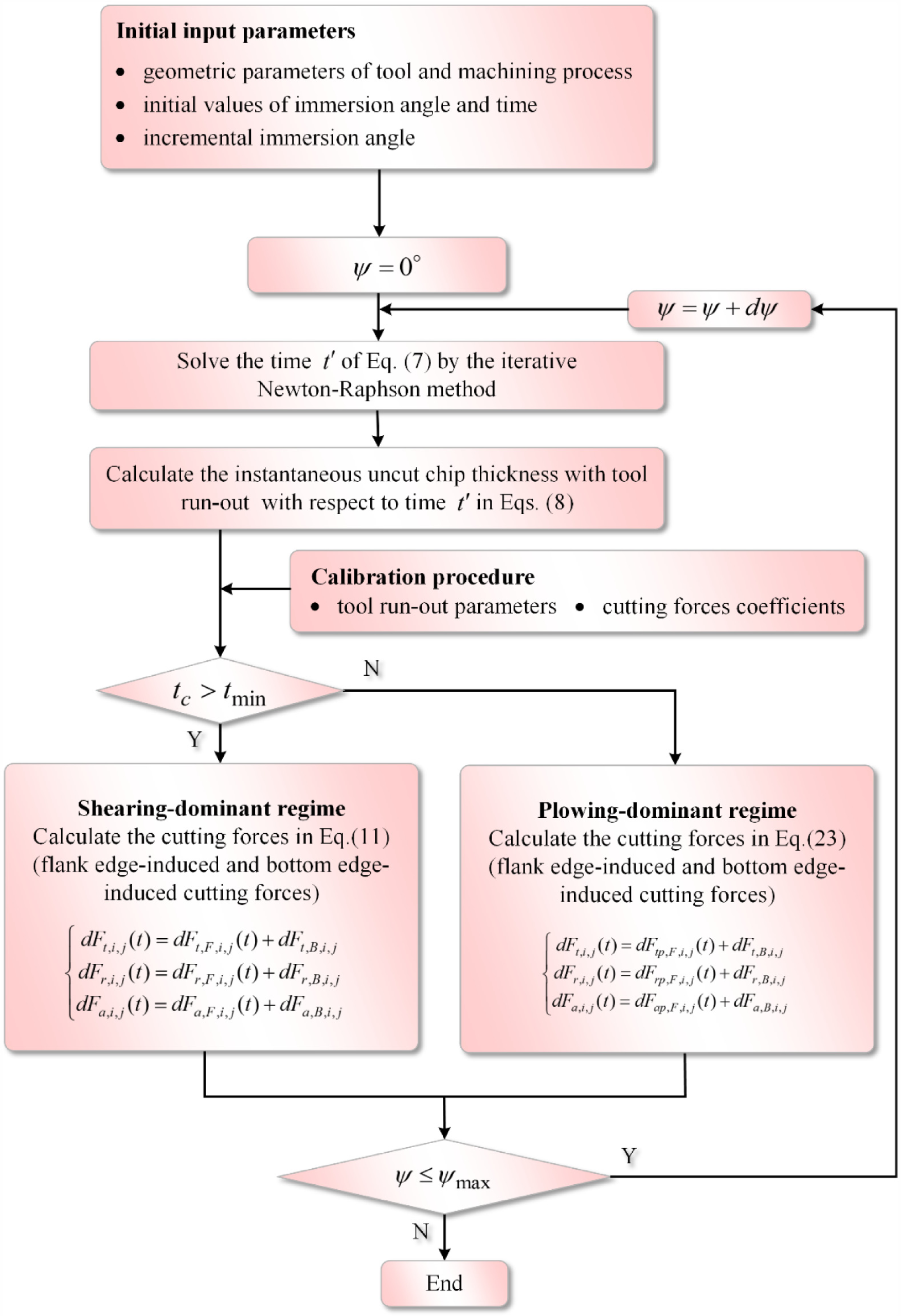
Simulation flow chart for predicting the cutting forces in micro flat end milling process.
Figures 8 and 9 show the comparison results between the experimental and predicted cutting forces of the micro flat end milling process in the presence of tool run-out and bottom edge cutting effect. It can also be seen from Figures 8 and 9 that the predicted cutting forces in the presence of tool run-out and bottom edge cutting effect fit well with the experimental ones both in magnitude and shape and the slight errors which around 10% are in the acceptable range. When the axial depth of cut is small and the feed rate is low, the predicted cutting forces containing the bottom edge cutting effect are much closer to the measured cutting forces. The effect of tool run-out and bottom edge cutting on the cutting forces cannot be negligible especially at low feed rates and small axial depth of cut. In addition, in the proposed cutting forces model considering tool run-out, the actual predicted cutting forces show similar periodic fluctuations in every flute pass, but the amplitudes in two adjacent tool rotations are not the same with each other as that in the conventional mechanistic models without considering tool run-out. There are still some discrepancies in the comparison results which may be caused by (1) the minimum chip thickness varied for different machining conditions and machined materials, (2) the effect of tool deflection caused by cutting forces and (3) the self-excited vibrations occurred in the micro flat end milling process.
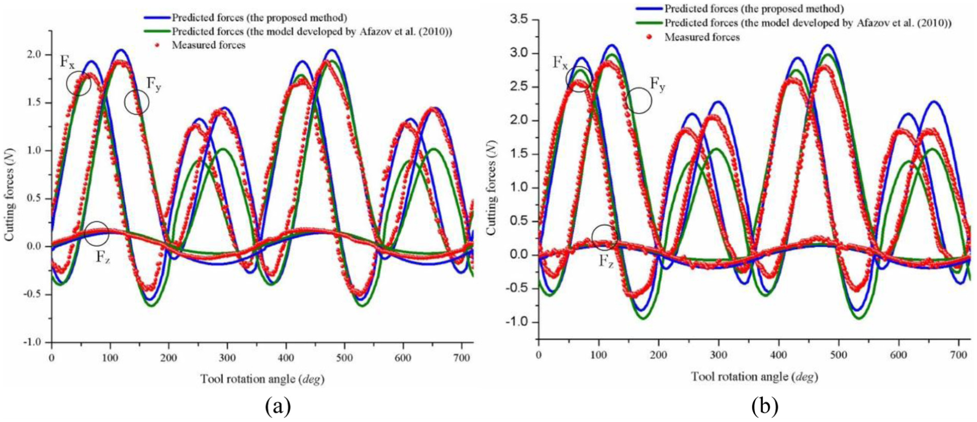
Comparison results of predicted and measured cutting forces about axial depth of cut: (a) Test 1 and (b) Test 2.
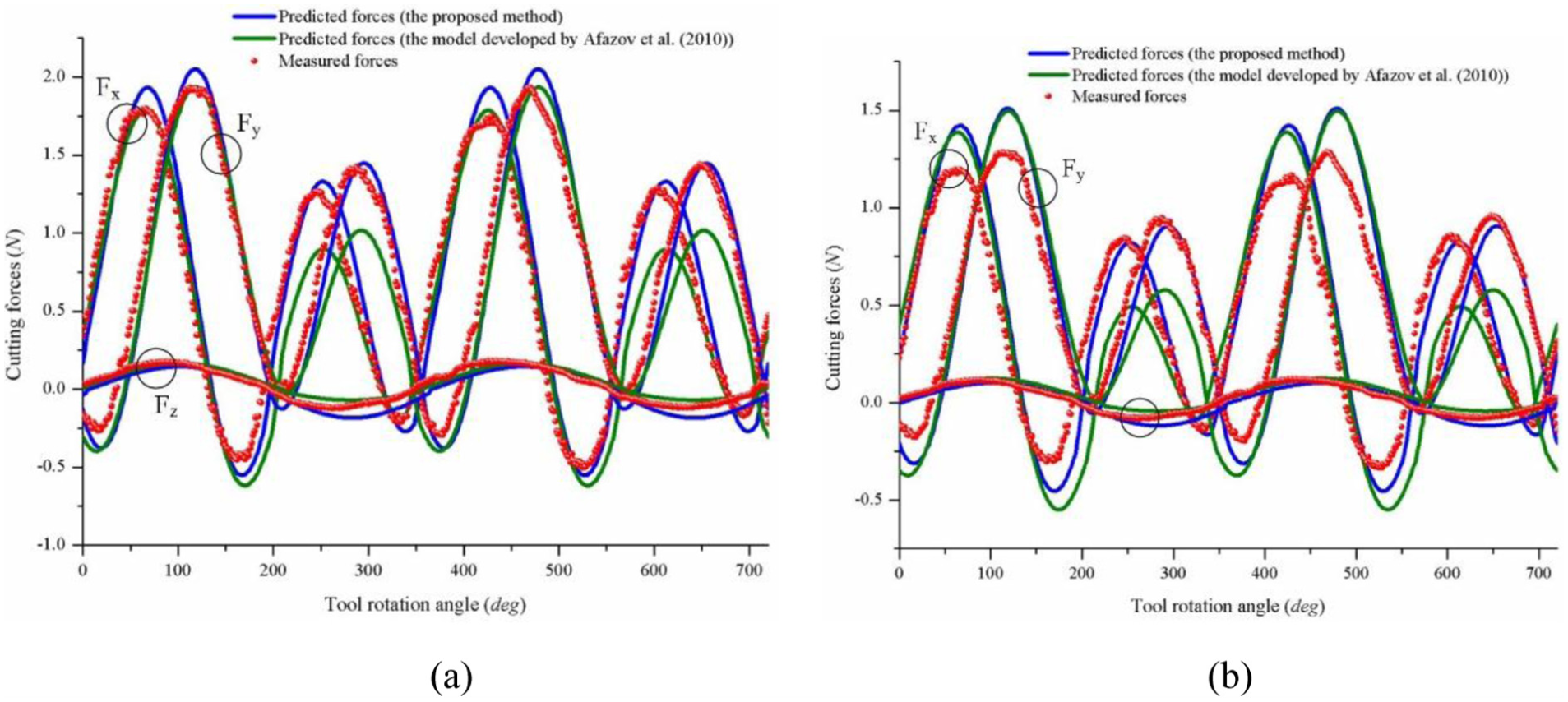
Comparison results of predicted and measured cutting forces about feed per tooth: (a) Test 2 and (b) Test 3.
Conclusion
This article proposes a cutting forces model for the micro flat end milling process considering the flank shearing, the flank ploughing and the bottom edge cutting mechanisms in the shearing-domain and ploughing-domain regimes, respectively. The trajectory of tool tip with the tool run-out is also included in the model. The calibration procedure of the corresponding cutting forces coefficients and tool run-out parameters is discussed in detail. The proposed cutting forces model has been validated by a series of micro milling tests. The average difference of all the tests between the predicted and experimental cutting forces was around 10%. From the above work, the following conclusions can be drawn out:
In the micro flat end milling process, the calculation of instantaneous uncut chip thickness and prediction of cutting forces for each flute are influenced significantly by the trochoidal trajectory of tool tip and tool run-out.
As the axial depth of cut is small in the micro flat end milling process, the influence of the bottom edge on cutting forces cannot be negligible. The cutting forces induced by bottom edge are treated as a linear function of bottom uncut chip width, which is approximately equal to the instantaneous uncut chip thickness.
Based on the calibration results of tool run-out parameters, the shearing cutting forces coefficients related to the flank edge are determined. They can be calibrated as the average slope of the linear fitting between the transformed cutting forces (tangential/radial/axial directions) and the chip load. Then the flank ploughing and bottom edge cutting coefficients can also be calibrated by the least-square fitting method.
Good agreements exist between the predicted and measured cutting forces under different machining conditions. The experiment validation results show that the proposed method is effective and accurate for predicting the cutting forces in the micro flat end milling process. The proposed cutting forces model would be helpful for acquiring high machining precision, micro machining monitoring and adaptive processing control. Further research needs to address the effects of tool deflection and process vibration which may lead to deviations between the predicted and experimental results.
Footnotes
Appendix 1
Acknowledgements
The authors would like to thank Prof. Kornel F. Ehamnn for guidance and help about the experiment.
Declaration of conflicting interests
The author(s) declared no potential conflicts of interest with respect to the research, authorship and/or publication of this article.
Funding
The author(s) disclosed receipt of the following financial support for the research, authorship, and/or publication of this article: This work is supported by the Basic Research Project Foundation of Ministry of Education N162410002-9 and the Advanced Manufacturing Processes Laboratory in Northwestern University.